Table of Contents
Advertisement
Quick Links
Advertisement
Table of Contents

Related Manuals for ASTRO AMC-2000


Summary of Contents for ASTRO AMC-2000
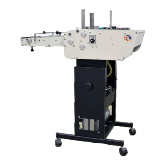
- Page 1 ASTRO ENVELOPE FEEDER AMC-2000 INSTALLATION AND OPERATING INSTRUCTIONS...
-
Page 2: Specifications
INTRODUCTION Thank you for purchasing the Astro Envelope Feeder. It is fast, efficient, reliable, and designed to provide many years of trouble-free service. Numerous built-in features of the Envelope Feeder combined with state-of-the art technology make this unit superior. Top load/bottom vacuum feed provides continuous printing of various sized envelopes, cards, and tags. -
Page 3: Parts List
PARTS LIST The following parts are included with this machine. Check and identify all parts with those listed below: ENVELOPE FEEDER 84-000-00 STAND WITH PUMP ASSEMBLY (See Page 13 & 14) PULSE GENERATOR 84-140-00 ASSEMBLY PLASTIC TIES (4) 123-0113 FRONT ENVELOPE GUIDE R/H 71-140-08 FRONT ENVELOPE GUIDE L/H 71-140-10... -
Page 4: Unpacking Instructions
UNPACKING INSTRUCTIONS 1. Unpack Stand and Feeder. Check parts against Parts List on Page 1. 2. Install four casters to base of Stand. 3. Place Feeder on top of Stand by locating two mating points on bottom of Feeder. [Fig. 1] 4. -
Page 5: Installation Instructions
INSTALLATION INSTRUCTIONS 1. Unplug Duplicator. 2. Remove rear right upper Side Cover from Duplicator. 3. Remove cross-brace bolt near buckle control gear. 4. Place Pulse Generator [Fig. 2] lower bracket over cross-brace bolt hole and reinstall bolt. DO NOT TIGHTEN at this time. 5. - Page 6 Figure 3 WARNING: FAILURE TO DO THIS RESULTS IN SERIOUS DAMAGE TO ENVELOPE FEEDER AND DUPLCATOR. 14. Move Paper Stack Height Adjustment to low position. 15. Turn Duplicator Hand Wheel so suction feet are in uppermost position. Remove two outer suction feet from Duplicator.
- Page 7 16. Roll Feeder up to Duplicator. Adjust height of Conveyor to match Duplicator Front Apron. If Feeder Front Stop Plate Hook is not even with upper edge of Duplicator’s Front Apron, adjust Feed Stand. To adjust Stand height [Figure 4]: Loosen two knobs on either side of Stand.
-
Page 8: Control Panel
CONTROLS CONTROL PANEL Figure Figure PUMP – Turns Feeder Pump ON and OFF. SET-UP – Feeder makes a full cycle bringing one envelope to Press. Mode Switch (#5) must be on MANUAL; Pump Switch (#7) must be ON and drive motor running. MODE SWITCH –... - Page 9 OPERATING INSTRUCTIONS 1. Adjust Envelope Feeder Stand to height of Press Front Feed Plate. 2. Hook Front Feed Plate on Envelope Feeder over bar on Press' Feeder. Tighten clamp screw assembly securely. 3. Plug Pulse Generator into connector provided on Envelope Feeder. Plug Pump into receptacle on Envelope Feeder.
- Page 10 12. Place a small stack of envelopes in Guides. 13. Using adjusting thumbscrew, make sure right edge of Push Guide is perpendicular to Front Stop Plate for accurate squareness. 14. Turn Feeder ON, set Mode Switch to MANUAL. Turn Speed Control clockwise so Conveyor Tapes are moving slowly.
- Page 11 27. Press SET-UP Switch momentarily. This brings down the envelope. 28. Turn Press Vacuum ON. Feeder is equipped with a Photoelectric Sensor [#1, Fig. 11], which synchronizes Figure 10 Feeder with Press and prevents jam-ups. In case Press does not pick up an envelope, Feeder will not send another envelope.
-
Page 12: Operating Hints
OPERATING HINTS A. Do not bend envelopes when setting Side Guides. Front and Rear Guides must be snug against envelopes. B. Form envelopes as required to maintain flatness to suction cups to improve feeding consistency. C. Be sure bottom envelope (in a stack of envelopes or tag stock), rests on Sheet Separators. -
Page 13: Lubrication Instructions
LUBRICATION INSTRUCTIONS WARNING! MACHINE MUST BE UNPLUGGED FROM POWER RECEPTACLE WHILE PERFORMING LUBRICATION, MAINTENANCE, OR CLEANING PROCEDURES. CAUTION TAKE CARE TO KEEP LUBRICANTS FROM ELECTRICAL TERMINALS, SWITCHES, AS WELL AS ROLLERS, BELTS AND RUBBER PARTS. When lubricating, pay particular attention to oil holes and all sliding parts. NOTE: Paper residue, dust, ink and other foreign materials MUST BE REMOVED from gears, working levers, shafts, and mechanisms before new lubricants are applied. - Page 14 FRONT COVER ASSEMBLY REMOVAL Turn power “ON”. Set MODE Switch to MANUAL. Turn Speed Control Knob CLOCKWISE so Conveyor tapes move slowly. Press Set Up Switch momentarily. Wait until Upper Pull-Out Roller touches Lower Pull-Out Roller and turn power OFF. Unplug Feeder.
- Page 15 STAND WITH PUMP Page 13...
- Page 16 STAND WITH PUMP PART NO. DESCRIPTION QTY. 156-102-18 ELEVATOR BRACKET 123-0017 SCREW, 10-32 x 1/4 PH, TRUSS 156-103-05 PANEL – BASE, PUMP COVER 156-103-07 SIDE PLATE R/H 156-103-06 SIDE PLATE L/H 156-103-25 ELEVATOR BRACKET SUPPORT 123-0695 SPRING PIN, 3/32 x 1/2 156-103-27 COLLAR 123-0841...
- Page 17 Page 15...
- Page 18 Copyright © 2015 Astro Machine Corporation Elk Grove Village, Illinois 60007 07/01/2015 PART NUMBER: 200-AMC2000 Rev. A...
Need help?
Do you have a question about the AMC-2000 and is the answer not in the manual?
Questions and answers