
Subscribe to Our Youtube Channel
Related Manuals for Landoll 2132


Summary of Contents for Landoll 2132
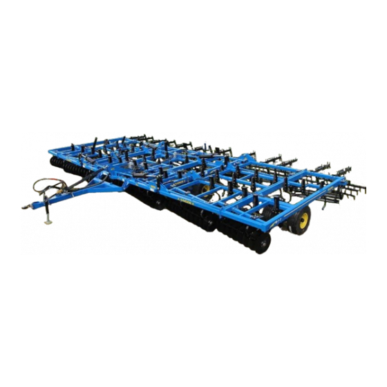
- Page 1 Model 2132 Coulter Chisel Operator’s Manual LANDOLL COMPANY, LLC 1900 North Street Marysville, Kansas 66508 (785) 562-5381 800-428-5655 ~ WWW.LANDOLL.COM F-1099-0521 05/2021-Present...
- Page 2 Manuals for the 2132 CC MANUAL NUMBER MANUAL NAME F-1099 2132 CC Operator’s Manual F-1100 2132 CC Parts Manual...
-
Page 3: Table Of Contents
Introduction and Safety Information Understanding Safety Statements ..........1-2 Decal Safety . - Page 4 Wheel Bearing Maintenance – Non Triple-Lip ........4-12 Wheel Bearing Maintenance -- Triple-Lip .
- Page 5 Introduction and Safety Information Introduction The Landoll Model 2132 CC is a quality product designed to give years of trouble free performance. By following each section of this manual, your system will perform as designed for you and your operation.
-
Page 6: Understanding Safety Statements
5. Use a locking-style hitch pin that properly fits the The safety statements contained in this manual relate to tractor drawbar and the implement hitch. Lock the the operation of the Model 2132 CC. tractor drawbar in the center position to prevent loss of steering control. -
Page 7: Attaching, Detaching, And Storage
INTRODUCTION AND SAFETY INFORMATION High Pressure Fluid Safety 6. Attach the safety chain to the tractor recommended drawbar support. Provide only enough slack in the 1. Escaping fluid under pressure can be nearly invisible chain for turning. Do not attach the safety chain to an and have enough force to penetrate the skin causing intermediate support. -
Page 8: Tire Safety
INTRODUCTION AND SAFETY INFORMATION Tire Safety Safety Chain 1. Tire changing can be dangerous and should be 1. Use a chain with a strength rating equal to or greater performed by trained personnel using correct tools than the gross weight of towed machinery, which is and equipment. -
Page 9: Standard Specifications
Introduction Warranty Registration This manual is compiled as a guide for owners and Be certain to register the Coulter Chisel Online operators of the 2132 CC. Read it carefully so as to be registration at www.landoll.com within 10 days of able to follow the suggestions made. -
Page 10: Warranty Statement
The sole obligation ofLandoll Company, LLC under this warranty shall be limited to repairing or replacing, at its option, part(s) which shall be identified to Landoll Company, LLC by way of a pre-authorized Landoll Company, LLC e-mail Warranty Claim Form Warranty, expressed or implied, will be denied on any product not properly registered with the Landoll Company, LLC Warranty Department within ten (10) days of the first retail sale. - Page 11 Landoll Company, LLC , loss of anticipated profits, transportation expenses due to repairs, non-operation or increased expense of...
-
Page 12: Model Specifications
STANDARD SPECIFICATIONS Model Specifications 2132 Coulter Chisel W/Auto Reset Shanks Model Number 2132-17 2132-19 2132-21 2132-23 2133-25 Working Width 21'-3” 23'-9” 26'-3” 28'-9” 31'-3” Transport Width 17'-0” 17'-0” 15'-8” 15'-6” 15'-6” Transport Height 10'-11” 12'-1” 13'-4” 14'-7” 15'-10” Number of Blades... - Page 13 STANDARD SPECIFICATIONS Specific Bolt Torques Lug Bolts & Nuts Torque (FT. LBS.) Disc Gang Shafts 1,200 Ft./Lbs. 5/8-18 Lug Bolts & Nuts 85-100 Ft./Lbs. 3/4-16 Lug Bolts & Nuts 250-265 Ft./Lbs.
-
Page 14: General Torque Specifications (Rev. 4/97)
STANDARD SPECIFICATIONS General Torque Specifications (rev. 4/97) TORQUE SPECIFIED IN FOOT POUNDS - This chart provides tightening torques for general purpose applications when special torques are not specified on process or drawing. Assembly torques apply to plated nuts and capscrews assembled without supplemental lubrication (as received condition). -
Page 15: Hydraulic Fitting Torque Specifications
STANDARD SPECIFICATIONS Hydraulic Fitting Torque Specifications TORQUE IS SPECIFIED IN FOOT POUNDS- 37 JIC, ORS, & ORB (REV. 10/97) This chart provides tightening torques for general purpose applications when special torques are not specified on process or drawing. Assembly torques apply to plated nuts and capscrews assembled without supplemental lubrication (as received condition). - Page 16 LOCATION OF OPTIONAL RT TWISTED SHOVELS, BLUE SHANK MOUNTS INDICATES LOCATION OF OPTIONAL LT TWISTED SHOVELS 5-1/2" 5-1/2" 5-1/2" 5-1/2" 5-1/2" 5-1/2" 5-1/2" 5-1/2" 5-1/2" 5-1/2" 5-1/2" 5-1/2" 20-1/2" 5-1/2" 5-1/2" 5-1/2" 5-1/2" Figure 2-4: Auto Reset Shank Placement 2132-17 F-1099-0521...
- Page 17 NOTE: RED SHANK MOUNTS INDICATES LOCATION OF OPTIONAL RT TWISTED SHOVELS, BLUE SHANK MOUNTS INDICATES LOCATION OF OPTIONAL LT TWISTED SHOVELS 5-1/2" 5-1/2" 5-1/2" 5-1/2" 5-1/2" 5-1/2" 5-1/2" 5-1/2" 5-1/2" 5-1/2" 20-1/2" 5-1/2" 5-1/2" 5-1/2" 5-1/2" 5-1/2" 5-1/2" Figure 2-5: Rigid Shank Placement 2132-17...
- Page 18 LOCATION OF OPTIONAL RT TWISTED SHOVELS, BLUE SHANK MOUNTS INDICATES LOCATION OF OPTIONAL LT TWISTED SHOVELS 5-1/2" 5-1/2" 5-1/2" 5-1/2" 5-1/2" 5-1/2" 5-1/2" 5-1/2" 5-1/2" 5-1/2" 20-1/2" 5-1/2" 5-1/2" 5-1/2" 5-1/2" 5-1/2" 5-1/2" 5-1/2" 5-1/2" Figure 2-6: Auto Reset Shank Placement 2132-19 2-10 F-1099-0521...
- Page 19 LOCATION OF OPTIONAL RT TWISTED SHOVELS, BLUE SHANK MOUNTS INDICATES LOCATION OF OPTIONAL LT TWISTED SHOVELS 5-1/2" 5-1/2" 5-1/2" 5-1/2" 5-1/2" 5-1/2" 5-1/2" 5-1/2" 5-1/2" 5-1/2" 5-1/2" 5-1/2" 5-1/2" 5-1/2" 20-1/2" 5-1/2" 5-1/2" 5-1/2" 5-1/2" Figure 2-7: Rigid Shank Placement 2132-19 2-11...
- Page 20 BLUE SHANK MOUNTS INDICATES LOCATION OF OPTIONAL LT TWISTED SHOVELS 5-1/2" 5-1/2" 5-1/2" 5-1/2" 5-1/2" 5-1/2" 5-1/2" 5-1/2" 5-1/2" 5-1/2" 5-1/2" 5-1/2" 20-1/2" 5-1/2" 5-1/2" 5-1/2" 5-1/2" 5-1/2" 5-1/2" 5-1/2" 5-1/2" Figure 2-8: Auto Reset Shank Placement 2132-21 2-12 F-1099-0521...
- Page 21 LOCATION OF OPTIONAL RT TWISTED SHOVELS, BLUE SHANK MOUNTS INDICATES LOCATION OF OPTIONAL LT TWISTED SHOVELS 5-1/2" 5-1/2" 5-1/2" 5-1/2" 5-1/2" 5-1/2" 5-1/2" 5-1/2" 5-1/2" 5-1/2" 5-1/2" 5-1/2" 20-1/2" 5-1/2" 5-1/2" 5-1/2" 5-1/2" 5-1/2" 5-1/2" 5-1/2" 5-1/2" Figure 2-9: Rigid Shank Placement 2132-21 2-13...
- Page 22 BLUE SHANK MOUNTS INDICATES LOCATION OF OPTIONAL LT TWISTED SHOVELS 5-1/2" 5-1/2" 5-1/2" 5-1/2" 5-1/2" 5-1/2" 5-1/2" 5-1/2" 5-1/2" 5-1/2" 5-1/2" 5-1/2" 5-1/2" 20-1/2" 5-1/2" 5-1/2" 5-1/2" 5-1/2" 5-1/2" 5-1/2" 5-1/2" 5-1/2" 5-1/2" Figure 2-10: Auto Reset Shank Placement 2132-23 2-14 F-1099-0521...
- Page 23 BLUE SHANK MOUNTS INDICATES LOCATION OF OPTIONAL LT TWISTED SHOVELS 5-1/2" 5-1/2" 5-1/2" 5-1/2" 5-1/2" 5-1/2" 5-1/2" 5-1/2" 5-1/2" 5-1/2" 5-1/2" 5-1/2" 20-1/2" 5-1/2" 5-1/2" 5-1/2" 5-1/2" 5-1/2" 5-1/2" 5-1/2" 5-1/2" 5-1/2" 5-1/2" Figure 2-11: Rigid Shank Placement 2132-23 2-15...
- Page 24 LOCATION OF OPTIONAL LT TWISTED SHOVELS 5-1/2" 5-1/2" 5-1/2" 5-1/2" 5-1/2" 5-1/2" 5-3/8" 5-1/2" 5-1/2" 5-3/8" 5-1/2" 5-1/2" 5-1/2" 5-1/2" 5-1/2" 20-1/2" 5-1/2" 5-1/2" 5-1/2" 5-1/2" 5-1/2" 5-1/2" 5-1/2" 5-1/4" 5-1/4" Figure 2-12: Auto Reset Shank Placement 2132-25 2-16 F-1099-0521...
- Page 25 BLUE SHANK MOUNTS INDICATES LOCATION OF OPTIONAL LT TWISTED SHOVELS 5-1/2" 5-1/2" 5-1/2" 5-1/2" 5-1/2" 5-1/2" 5-1/2" 5-1/2" 5-1/2" 5-1/2" 5-1/2" 5-1/2" 5-1/2" 20-1/2" 5-1/2" 5-1/2" 5-1/2" 5-1/2" 5-1/2" 5-1/2" 5-1/2" 5-1/2" 5-1/2" 5-5/16" 5-5/16" Figure 2-13: Rigid Shank Placement 2132-25 2-17...
- Page 26 STANDARD SPECIFICATIONS NOTE: LOCATION OF 5-15/16" 4-11/16" HARROW ADJUSTMENT WRENCH’S 19-5/8" 3 TINE HARROW ASSEMBLY W/EXT LH REEL/GANGBAR 28-5/8" ASSEMBLY 82” 5 TINE HARROW CTR ASSEMBLY REEL/GANGBAR ASSEMBLY 114” Figure 2-14: Std 3BCT/Chopper Placement 2132-17 LH 2-18 F-1099-0521...
- Page 27 STANDARD SPECIFICATIONS 5-9/16" NOTE: LOCATION OF 4-11/16" HARROW ADJUSTMENT WRENCH’S 19-5/8" 3 TINE HARROW ASSEMBLY W/EXT RH REEL/GANGBAR 28-5/8" ASSEMBLY 82” 5 TINE HARROW CTR ASSEMBLY REEL/GANGBAR ASSEMBLY 114” Figure 2-15: Std 3BCT/Chopper Placement 2132-17 RH 2-19...
- Page 28 STANDARD SPECIFICATIONS NOTE: LOCATION OF 4-3/4" 6" HARROW ADJUSTMENT WRENCH’S 34-1/2" 4 TINE HARROW ASSEMBLY LH REEL/GANGBAR 28-5/8" ASSEMBLY 97” 5 TINE HARROW CTR ASSEMBLY REEL/GANGBAR ASSEMBLY 114” Figure 2-16: Std 3BCT/Chopper Placement 2132-19 LH 2-20 F-1099-0521...
- Page 29 STANDARD SPECIFICATIONS NOTE: LOCATION OF 4-3/4" 6" HARROW ADJUSTMENT WRENCH’S 34-1/2" 4 TINE HARROW ASSEMBLY RH REEL/GANGBAR 28-5/8" ASSEMBLY 97” 5 TINE HARROW CTR ASSEMBLY REEL/GANGBAR ASSEMBLY 114” Figure 2-17: Std 3BCT/Chopper Placement 2132-19 RH 2-21...
- Page 30 STANDARD SPECIFICATIONS NOTE: LOCATION OF 3-7/8" 17" HARROW ADJUSTMENT WRENCH’S 19-1/4" 4 TINE HARROW ASSEMBLY LH REEL/GANGBAR 28-5/8" ASSEMBLY 114” 6 TINE HARROW CTR ASSEMBLY REEL/GANGBAR ASSEMBLY 114” Figure 2-18: Std 3BCT/Chopper Placement 2132-21 LH 2-22 F-1099-0521...
- Page 31 STANDARD SPECIFICATIONS NOTE: LOCATION OF 4-1/8" 17" HARROW ADJUSTMENT WRENCH’S 19-1/4" 4 TINE HARROW ASSEMBLY RH REEL/GANGBAR 28-5/8" ASSEMBLY 114” 6 TINE HARROW CTR ASSEMBLY REEL/GANGBAR ASSEMBLY 114” Figure 2-19: Std 3BCT/Chopper Placement 2132-21 RH 2-23...
- Page 32 STANDARD SPECIFICATIONS 4-11/16" NOTE: LOCATION 3-11/16" OF HARROW ADJUSTMENT WRENCH’S 34-1/4" 5 TINE HARROW ASSEMBLY LH REEL/GANGBAR 28-5/8" ASSEMBLY 129” 5 TINE HARROW CTR ASSEMBLY REEL/GANGBAR ASSEMBLY 114” Figure 2-20: Std 3BCT/Chopper Placement 2132-23 LH 2-24 F-1099-0521...
- Page 33 STANDARD SPECIFICATIONS 4-11/16" NOTE: LOCATION 3-11/16" OF HARROW ADJUSTMENT WRENCH’S 34-1/4" 5 TINE HARROW ASSEMBLY RH REEL/GANGBAR 28-5/8" ASSEMBLY 129” 5 TINE HARROW CTR ASSEMBLY REEL/GANGBAR ASSEMBLY 114” Figure 2-21: Std 3BCT/Chopper Placement 2132-23 RH 2-25...
- Page 34 STANDARD SPECIFICATIONS NOTE: LOCATION 15-3/4" 16-11/16" OF HARROW ADJUSTMENT WRENCH’S 41-3/4" 5 TINE HARROW ASSEMBLY LH REEL/GANGBAR 36-1/4" ASSEMBLY 129” 6 TINE HARROW CTR ASSEMBLY REEL/GANGBAR ASSEMBLY 129” Figure 2-22: Std 3BCT/Chopper Placement 2132-25 LH 2-26 F-1099-0521...
- Page 35 STANDARD SPECIFICATIONS NOTE: LOCATION 15-3/4" 16-11/16" OF HARROW ADJUSTMENT WRENCH’S 41-3/4" 5 TINE HARROW ASSEMBLY LH REEL/GANGBAR 36-1/4" ASSEMBLY 129” 6 TINE HARROW CTR ASSEMBLY REEL/GANGBAR ASSEMBLY 129” Figure 2-23: Std 3BCT/Chopper Placement 2132-25 RH 2-27...
- Page 36 NOTE: LOCATION 5-15/16" 4-11/16" OF HARROW ADJUSTMENT WRENCH’S AND HOSE MOUNT PLATES 19-9/16" 3 TINE W/EXT HARROW ASSEMBLY LH REEL/GANGBAR ASSEMBLY 82” 28-5/8" 5 TINE HARROW CTR ASSEMBLY REEL/GANGBAR ASSEMBLY 114” Figure 2-24: Hyd 3BCT/Chopper Placement 2132-17 LH 2-28 F-1099-0521...
- Page 37 NOTE: LOCATION " 4-11/16" 5-9/16" OF HARROW ADJUSTMENT WRENCH’S AND HOSE MOUNT PLATES 19-11/16" 3 TINE W/EXT HARROW ASSEMBLY RH REEL/GANGBAR ASSEMBLY 82” 28-5/8" 5 TINE HARROW CTR ASSEMBLY REEL/GANGBAR ASSEMBLY 114” Figure 2-25: Hyd 3BCT/Chopper Placement 2132-17 RH 2-29...
- Page 38 STANDARD SPECIFICATIONS 6" 4-3/4" NOTE: LOCATION OF HARROW ADJUSTMENT WRENCH’S AND HOSE MOUNT PLATES 34-1/2" 4 TINE HARROW ASSEMBLY LH REEL/GANGBAR ASSEMBLY 97” 28-5/8" 5 TINE HARROW CTR ASSEMBLY REEL/GANGBAR ASSEMBLY 114” Figure 2-26: Hyd 3BCT/Chopper Placement 2132-19 LH 2-30 F-1099-0521...
- Page 39 STANDARD SPECIFICATIONS 4-3/4" 6" NOTE: LOCATION OF HARROW ADJUSTMENT WRENCH’S AND HOSE MOUNT PLATES 34-1/2" 4 TINE HARROW ASSEMBLY RH REEL/GANGBAR ASSEMBLY 97” 28-5/8" 5 TINE HARROW CTR ASSEMBLY REEL/GANGBAR ASSEMBLY 114” Figure 2-27: Hyd 3BCT/Chopper Placement 2132-19 RH 2-31...
- Page 40 STANDARD SPECIFICATIONS NOTE: LOCATION 3-7/8" 17" OF HARROW ADJUSTMENT WRENCH’S AND HOSE MOUNT PLATES 19-1/4" 4 TINE HARROW ASSEMBLY LH REEL/GANGBAR 28-5/8" ASSEMBLY 114” 6 TINE HARROW CTR ASSEMBLY REEL/GANGBAR ASSEMBLY 114” Figure 2-28: Hyd 3BCT/Chopper Placement 2132-21 LH 2-32 F-1099-0521...
- Page 41 STANDARD SPECIFICATIONS NOTE: LOCATION 4-1/8" 17" OF HARROW ADJUSTMENT WRENCH’S AND HOSE MOUNT PLATES 19-1/4" 4 TINE HARROW ASSEMBLY RH REEL/GANGBAR 28-5/8" ASSEMBLY 114” 6 TINE HARROW CTR ASSEMBLY REEL/GANGBAR ASSEMBLY 114” Figure 2-29: Hyd 3BCT/Chopper Placement 2132-21 RH 2-33...
- Page 42 STANDARD SPECIFICATIONS NOTE: LOCATION 3-11/16" 4-11/16" OF HARROW ADJUSTMENT WRENCH’S AND HOSE MOUNT PLATES 34-1/4" 5 TINE HARROW ASSEMBLY LH REEL/GANGBAR 28-5/8" ASSEMBLY 129” 5 TINE HARROW CTR ASSEMBLY REEL/GANGBAR ASSEMBLY 114” Figure 2-30: Hyd 3BCT/Chopper Placement 2132-23 LH 2-34 F-1099-0521...
- Page 43 STANDARD SPECIFICATIONS NOTE: LOCATION 4-11/16" 3-11/16" OF HARROW ADJUSTMENT WRENCH’S AND HOSE MOUNT PLATES 34-1/4" 5 TINE HARROW ASSEMBLY RH REEL/GANGBAR 28-5/8" ASSEMBLY 129” 5 TINE HARROW CTR ASSEMBLY REEL/GANGBAR ASSEMBLY 114” Figure 2-31: Hyd 3BCT/Chopper Placement 2132-23 RH 2-35...
- Page 44 STANDARD SPECIFICATIONS NOTE: LOCATION 15-3/4" 16-1/2" OF HARROW ADJUSTMENT WRENCH’S AND HOSE MOUNT 41-3/4" PLATES 5 TINE HARROW ASSEMBLY LH REEL/GANGBAR 36-1/4" ASSEMBLY 129” 6 TINE HARROW CTR ASSEMBLY REEL/GANGBAR ASSEMBLY 129” Figure 2-32: Hyd 3BCT/Chopper Placement 2132-25 LH 2-36 F-1099-0521...
- Page 45 STANDARD SPECIFICATIONS NOTE: LOCATION 16-1/2" 8-1/4" OF HARROW ADJUSTMENT WRENCH’S AND HOSE MOUNT 41-3/4" PLATES 5 TINE HARROW ASSEMBLY RH REEL/GANGBAR 36-1/4" ASSEMBLY 129” 6 TINE HARROW CTR ASSEMBLY REEL/GANGBAR ASSEMBLY 129” Figure 2-33: Hyd 3BCT/Chopper Placement 2132-25 RH 2-37...
- Page 46 STANDARD SPECIFICATIONS 19-5/8" REEL/GANGBAR ASSEMBLY 82” 28-5/8" REEL/GANGBAR ASSEMBLY 114” Figure 2-34: Std Chopper Reel Placement 2132-17 LH 2-38 F-1099-0521...
- Page 47 STANDARD SPECIFICATIONS 19-5/8" REEL/GANGBAR ASSEMBLY 82” 28-5/8" REEL/GANGBAR ASSEMBLY 114” Figure 2-35: Std Chopper Reel Placement 2132-17 RH 2-39...
- Page 48 STANDARD SPECIFICATIONS 34-1/2" REEL/GANGBAR ASSEMBLY 97” 28-5/8" REEL/GANGBAR ASSEMBLY 114” Figure 2-36: Std Chopper Reel Placement 2132-19 LH 2-40 F-1099-0521...
- Page 49 STANDARD SPECIFICATIONS 34-1/2" REEL/GANGBAR ASSEMBLY 97” 28-5/8" REEL/GANGBAR ASSEMBLY 114” Figure 2-37: Std Chopper Reel Placement 2132-19 RH 2-41...
- Page 50 STANDARD SPECIFICATIONS 19-1/4" REEL/GANGBAR ASSEMBLY 114” 28-5/8" REEL/GANGBAR ASSEMBLY 114” Figure 2-38: Std Chopper Reel Placement 2132-21 LH 2-42 F-1099-0521...
- Page 51 STANDARD SPECIFICATIONS 19-1/4" REEL/GANGBAR ASSEMBLY 114” 28-5/8" REEL/GANGBAR ASSEMBLY 114” Figure 2-39: Std Chopper Reel Placement 2132-21 RH 2-43...
- Page 52 STANDARD SPECIFICATIONS 34-1/4" REEL/GANGBAR ASSEMBLY 129” 28-5/8" REEL/GANGBAR ASSEMBLY 114” Figure 2-40: Std Chopper Reel Placement 2132-23 LH 2-44 F-1099-0521...
- Page 53 STANDARD SPECIFICATIONS 34-1/4" REEL/GANGBAR ASSEMBLY 129” 28-5/8" REEL/GANGBAR ASSEMBLY 114” Figure 2-41: Std Chopper Reel Placement 2132-23 RH 2-45...
- Page 54 STANDARD SPECIFICATIONS 41-3/4" REEL/GANGBAR ASSEMBLY 129” 36-1/8" REEL/GANGBAR ASSEMBLY 129” Figure 2-42: Std Chopper Reel Placement 2132-25 LH 2-46 F-1099-0521...
- Page 55 STANDARD SPECIFICATIONS 41-3/4" REEL/GANGBAR ASSEMBLY 129” 36-1/8" REEL/GANGBAR ASSEMBLY 129” Figure 2-43: Std Chopper Reel Placement 2132-25 RH 2-47...
- Page 56 STANDARD SPECIFICATIONS 19-5/8" REEL/GANGBAR ASSEMBLY 82” 28-5/8" REEL/GANGBAR ASSEMBLY 114” Figure 2-44: Hyd Chopper Reel Placement 2132-17 LH 2-48 F-1099-0521...
- Page 57 STANDARD SPECIFICATIONS 19-5/8" REEL/GANGBAR ASSEMBLY 82” 28-5/8" REEL/GANGBAR ASSEMBLY 114” Figure 2-45: Hyd Chopper Reel Placement 2132-17 RH 2-49...
- Page 58 STANDARD SPECIFICATIONS 34-1/2" REEL/GANGBAR ASSEMBLY 97” 28-5/8" REEL/GANGBAR ASSEMBLY 114” Figure 2-46: Hyd Chopper Reel Placement 2132-19 LH 2-50 F-1099-0521...
- Page 59 STANDARD SPECIFICATIONS 34-1/2" REEL/GANGBAR ASSEMBLY 97” 28-5/8" REEL/GANGBAR ASSEMBLY 114” Figure 2-47: Hyd Chopper Reel Placement 2132-19 RH 2-51...
- Page 60 STANDARD SPECIFICATIONS 19-1/4" REEL/GANGBAR ASSEMBLY 114” 28-5/8" REEL/GANGBAR ASSEMBLY 114” Figure 2-48: Hyd Chopper Reel Placement 2132-21 LH 2-52 F-1099-0521...
- Page 61 STANDARD SPECIFICATIONS 19-1/4" REEL/GANGBAR ASSEMBLY 114” 28-5/8" REEL/GANGBAR ASSEMBLY 114” Figure 2-49: Hyd Chopper Reel Placement 2132-21 RH 2-53...
- Page 62 STANDARD SPECIFICATIONS 34-1/4" REEL/GANGBAR ASSEMBLY 129” 28-5/8" REEL/GANGBAR ASSEMBLY 114” Figure 2-50: Hyd Chopper Reel Placement 2132-23 LH 2-54 F-1099-0521...
- Page 63 STANDARD SPECIFICATIONS 34-1/4" REEL/GANGBAR ASSEMBLY 129” 28-5/8" REEL/GANGBAR ASSEMBLY 114” Figure 2-51: Hyd Chopper Reel Placement 2132-23 RH 2-55...
- Page 64 STANDARD SPECIFICATIONS 41-3/4" REEL/GANGBAR ASSEMBLY 129” 36-1/8" REEL/GANGBAR ASSEMBLY 129” Figure 2-52: Hyd Chopper Reel Placement 2132-25 LH 2-56 F-1099-0521...
- Page 65 STANDARD SPECIFICATIONS 41-3/4" REEL/GANGBAR ASSEMBLY 129” 36-1/8" REEL/GANGBAR ASSEMBLY 129” Figure 2-53: Hyd Chopper Reel Placement 2132-25 RH 2-57...
- Page 66 STANDARD SPECIFICATIONS Table provided for general use. NOTES: 2-58 F-1099-0521...
-
Page 67: Assembly Instructions
Chapter 3 Assembly Instructions It is very important that your new 2132 Coulter Chisel be WARNING properly assembled, adjusted and lubricated before use. Illustrations to assist with the assembly process are Do not attempt to lift heavy parts (such as the provided in “Standard Specifications”... -
Page 68: Center Frame Assembly
3-2. Torque to 250-265 ft/lbs. NOTE The valve stems will face outwards. 4. Install the 2132 front manifold assembly on 2 hole plate on front of center frame tube using 1/2 x 4 bolt Figure 3-1: SIS 20mph Decal Installation and 1/2 lock nut. - Page 69 REEL ATTACHMENT ONLY SIS DECALBRACKET, 1/4 X 1 BOLT, NOTE: FRONT FOLD BRACKET ASSEMBLY 1/4 LOCK NUT USED ON MODELS 2132-21’-23’-25’ ONLY, REAR 8 PORT MANIFOLD MOUNTS ON 8 PORT MANIFOLD, FRONT PLATE, FRONT 8 PORT MANIFOLD 1/2 X 4-1/2 BOLT,...
-
Page 70: Hitch Installation
ASSEMBLY INSTRUCTIONS Hitch Installation 5. Install the hose holder bracket to the front of the hitch assembly with 3/4 x 2 bolt, 3/4 flat washer and 3/4 1. Attach the hitch assembly to the front of the center lock nut. frame using hitch pins, 1”... - Page 71 ASSEMBLY INSTRUCTIONS HOSE STORAGE PLATE, 1 X 11 BOLT, 1 FLAT WASHERS 1 LOCK NUT WING NUT, HOSE CLAMP LONG, 3/8 X 5 BOLT ALL THREAD HITCH PIN, 1/2 X 2-1/4 ROLL PIN, STOR-A-WAY, 1” LOCK NUT 1/4 X 1 BOLTS, HOSE CLAMPS 1/4 LOCK NUTS 3/8 X 3-1/2 BOLT,...
-
Page 72: Hitch Leveling Installation
ASSEMBLY INSTRUCTIONS Hitch Leveling Installation 3. Connect front of leveler tube weldment to the rear hole of leveler tower using hitch pin, 1 lock nuts and 1. Connect narrow end of the leveler tower to the top 1/2 x 2-1/4 roll pin. hole on rear of the hitch assembly using 1-1/4-7 x 4. - Page 73 ASSEMBLY INSTRUCTIONS LEVELER TUBE WELDMENT HITCH PIN, 1 X 11 BOLT, 1 LOCK NUT LEVELER TOWER HITCH PIN, 1/2 X 2-1/4 ROLL PIN, 1” LOCK NUT HITCH PIN, 1/2 X 2-1/4 ROLL PIN, RADIUS 1” LOCK NUT ASSEMBLY NOTE: ATTACH LEVER TUBE WELDMENT TO MIDDLE SET OF HOLES IN CENTER LIFT ASSEMBLY...
-
Page 74: Wing Frame Installation
Do not attempt to lift heavy parts, such as the with 5-16 x 2-1/2 roll pins wing frame, manually. Use a hoist or a forklift to 6. Models 2132-21-23-25 repeat same procedure for move these parts into position. front fold bracket assembly. - Page 75 ASSEMBLY INSTRUCTIONS NOTE: FRONT FOLD BRACKET AND FOLD CYLINDERS USED ON MODELS 2123-21’-23’-25’ ONLY, REAR FOLD CYLINERS INSTALLATION SAME AS FRONT NOTE: CYLINDER MOUNT PLATES, MOUNT ON INSIDE OF FOLD CYLINDER MOUNT PLATES, ROD END OF CYLINDER PINS GO THROUGH HOLES OF CYLINDER MOUNT PLATES 4 X 30 CYLINDER 1-3/4 FLANGE BEARINGS...
-
Page 76: Coulter Gang Installation
ASSEMBLY INSTRUCTIONS Coulter Gang Installation 3. Attach the base end of the 3-3/4 x 8 cylinder to the coulter spring assembly attached to the left center frame weldment using the clevis pins and roll pins DANGER provided with cylinder. 4. - Page 77 ASSEMBLY INSTRUCTIONS CYLINDER 3-1/2 X 8, PINS PROVIDED WITH CYLINDER CYLINDER 3-1/4 X 8, PINS PROVIDED WITH CYLINDER COULTER SPRING ASSEMBLY DEPTH GAUGE GUIDE, 5/8 X 6-11/16 X 7-1/2 U-BOLT, 1 FLANGE LOCK NUT, DEPTH GAUGE MOUNT, 5/8 X 7-11/16 X 5-1/2 U-BOLT, CYLINDER 3-3/4 X 8, 1 FLANGE LOCK NUT, PINS PROVIDED...
- Page 78 GANG ASSEMBLY GANG ASSEMBLY GANG ASSEMBLY GANG ASSEMBLY LH 8 BLADE LH 9 BLADE RH 10 BLADE RH 8 BLADE 2132-17 GANG ASSEMBLY GANG ASSEMBLY GANG ASSEMBLY GANG ASSEMBLY LH 10 BLADE LH 9 BLADE RH 10 BLADE RH 10 BLADE...
- Page 79 ASSEMBLY INSTRUCTIONS Table provided for general use. NOTES: 3-13...
-
Page 80: Auto Reset Shank Installation
ASSEMBLY INSTRUCTIONS Auto Reset Shank Installation 2. Install the 2” cast flat point onto shanks with 1/2 x 3-3/4 bolts, 1/2 hd flat washers and 1/2 heavy nuts. 1. Attach each shank to each auto reset clamp 3. Install the 2” cast point onto shanks with 1/2 x 3-1/4 assembly using 3/4 x 4 bolt, lock nut in bottom hole bolts, 1/2 hd flat washers and 1/2 heavy nuts. - Page 81 ASSEMBLY INSTRUCTIONS AUTO RESET CLAMP ASSEMBLY LT AUTO RESET CLAMP ASSEMBLY RT 3/4 X 5 BOLT, 3/4 LOCK NUT 3/4 X 4 BOLT, 3/4 LOCK NUT SHANK 2” CAST FLAT POINT 1/2 X 3-3/4 BOLT, 1/2 HD FLAT WASHER, 1/2 HEAVY NUT 2”...
-
Page 82: Rigid Shear Bolt Clamp Shank Installation
ASSEMBLY INSTRUCTIONS Rigid Shear Bolt Clamp Shank 2. Install the 2” cast flat point onto shanks with 1/2 x 3-3/4 bolts, 1/2 hd flat washers and 1/2 heavy nuts. Installation 3. Install the 2” cast point onto shanks with 1/2 x 3-1/4 1. - Page 83 ASSEMBLY INSTRUCTIONS 12” OFFSET SHEAR BOLT CLAMP 8” OFFSET 5/8 X 5-1/2 GR. 8 BOLT, SHEAR BOLT CLAMP 5/8 X 3/4 X 1-1/4 BUSHINGS, 5/8 FLAT WASHERS, 5/8 LOCK NUTS 3/4 X 4 BOLT, 3/4 LOCK NUT 1/2 X 3-3/4 BOLT, 1/2 HD FLAT WASHER, 1/2 HEAVY NUT 2”...
-
Page 84: Hydraulic Installation
ASSEMBLY INSTRUCTIONS Hydraulic Installation See Figures 3-10 through See Figures 3-12 for lift hydraulic installation. See Figures 3-13 through See Figures 3-16 for fold hydraulic installation. NOTE 3. Rod ends of fold cylinders need to be left unassembled until fold hydraulic system is fully charged with oil to prevent machine damage. - Page 85 ASSEMBLY INSTRUCTIONS 4 X 16 CYLINDER 4-1/2 X 16 3/8” X 159” (2132-17-19) CYLINDER 3/8” X 185” (2132-21-23-25) HOSE 4-1/2 X 16 CYLINDER 4 X 16 CYLINDER DETAIL A 90° #10 90° #8 ADAPTER 3/8” X 76” ADAPTER HOSE LIMIT VALVE 1/2”...
- Page 86 ASSEMBLY INSTRUCTIONS NOTE: RUN HOSES THROUGH ALL HOSE CLAMPS AND LOOPS NOTE: RUN HOSES UNDER PLATES NOTE: RUN HOSES THROUGH ALL HOSE CLAMPS AND LOOPS Figure 3-11: Lift Hydraulic Layout LH 3-20 F-1099-0521...
- Page 87 ASSEMBLY INSTRUCTIONS NOTE: RUN HOSES UNDER PLATES NOTE: RUN HOSES THROUGH ALL HOSE CLAMPS AND LOOPS Figure 3-12: Lift Hydraulic Layout RH 3-21...
- Page 88 OF MANIFOLD ASSEMBLY FRONT OF MACHINE 22 PORT 22 PORT MANIFOLD MANIFOLD DETAIL A ASSEMBLY ASSEMBLY 3/4-16 3/4-16 2132 FRONT 2132 FRONT PLUG PLUG MANIFOLD MANIFOLD (REAR VIEW) (REAR VIEW) ADAPTER 45° #8 ADAPTER Figure 3-13: Fold Hydraulic Installation 2132-17-19’ 3-22 F-1099-0521...
- Page 89 ASSEMBLY INSTRUCTIONS NOTE: RUN HOSES THROUGH ALL LOOPS, CLAMPS, TO FRONT OF HITCH NOTE: RUN HOSES THROUGH ALL LOOPS Figure 3-14: Fold Hydraulic Layout 2132-17-19 3-23...
- Page 90 ROW UP FROM BOTTOM, PORTS COUPLER OF MANIFOLD ASSEMBLY FRONT OF MACHINE 22 PORT 22 PORT DETAIL A MANIFOLD MANIFOLD ASSEMBLY ASSEMBLY 2132 FRONT 45° #8 2132 FRONT ADAPTER ADAPTER MANIFOLD MANIFOLD (REAR VIEW) (REAR VIEW) Figure 3-15: Fold Hydraulic Installation 2132-21-23-25 3-24 F-1099-0521...
- Page 91 ASSEMBLY INSTRUCTIONS NOTE: RUN HOSES THROUGH ALL LOOPS, CLAMPS, TO FRONT OF HITCH NOTE: RUN HOSES THROUGH ALL LOOPS Figure 3-16: Fold Hydraulic Layout 2132-21-23-25 3-25...
- Page 92 ASSEMBLY INSTRUCTIONS Table provided for general use. NOTES: 3-26 F-1099-0521...
- Page 93 ASSEMBLY INSTRUCTIONS 3-1/4 X 8 CYLINDER 3/8” X 140” (2132-17-19) 3/8” X 168” (2132-21-23-25) HOSE 3/8” X 168” (2132-17-19) 3/8” X 196” (2132-21-23-25) 3-1/2 X 8 HOSE CYLINDER 90° #8 1/16” 3/8” X 123-1/4” RESTRICTOR HOSE ADAPTER 90° #8 (NOTE: LOCATION...
- Page 94 ASSEMBLY INSTRUCTIONS NOTE: RUN HOSES THROUGH ALL HOSE CLAMPS AND LOOPS NOTE: RUN HOSES UNDER PLATES NOTE: RUN HOSES THROUGH ALL HOSE CLAMPS AND LOOPS 4 X 8 3-3/4 X 8 CYLINDER CYLINDER Figure 3-18: Coulter Gang Hydraulic Layout LH 3-28 F-1099-0521...
- Page 95 ASSEMBLY INSTRUCTIONS NOTE: RUN HOSES UNDER PLATES NOTE: RUN HOSES THROUGH ALL HOSE CLAMPS AND LOOPS NOTE: LOCATION OF 1/16” RESTRICTOR 3-1/2 X 8 3-1/4 X 8 CYLINDER CYLINDER Figure 3-19: Coulter Gang Hydraulic Layout RH 3-29...
- Page 96 ASSEMBLY INSTRUCTIONS Figure 3-20: LED Light Harness Wire Designations 3-30 F-1099-0521...
-
Page 97: Led Light Installation
ASSEMBLY INSTRUCTIONS LED Light Installation IMPORTANT Make sure lights are positioned for maximum NOTE visibility from the rear See Figures 3-22. Refer to See Figure 3-22 for light bracket and wiring 5. Install the rear warning light harness to the frame. harnesses placement. - Page 98 ASSEMBLY INSTRUCTIONS TAIL LIGHT MOUNT, RED AG LAMP, MOUNT BRACKET, REFLECTOR MOUNT, 1/2 X 10 BOLTS, 1/4 X 1-1/2 BOLTS, 1/2 FLAT WASHERS, LOCK NUTS 1/2 LOCK NUTS AG FLASHER 34” HARNESS LIGHT BRACKET ASSEMBLY RH, CONTROL MODULE, EXTENSIONS LIGHT MOUNT, LIGHT PLATE, 1/4 X 1-1/2 BOLTS, 5/8 X 13 X 3-5/8 U-BOLTS, 1/4 LOCK NUTS...
- Page 99 ASSEMBLY INSTRUCTIONS NOTE: SECURE LIGHT HARNESSES MAIN LIGHT HARNESS, WITH TIES STRAPS AS NEDDED 7-PIN CONNECTOR TO KEEP CLEAR OF ANY TO TRACTOR MOVING PARTS LIGHT HARNESS 132” EXTENSION 2” 2” 5-1/4” 5-1/4” NOTE: RUN NOTE: RUN LIGHT HARNESSES 132” LIGHT HARNESSES 204”...
- Page 100 ASSEMBLY INSTRUCTIONS 3BCT/Chopper Reel Installation 9. On hydraulic 3BCT/Chopper Reel option, install the bulkhead tee w/nut and 90° adapter swivel to plate on (Option) frame as shown See Figures 3-24. NOTE BULKHEAD BULKHEAD TEE W/NUT Refer to See Figures 2-14 through See Figures 2-23 for Standard 3BCT/Chopper Reel Placement.
- Page 101 ASSEMBLY INSTRUCTIONS COMBO HARROW HARROW ADJ WRENCH, MOUNT ARM, QUICK HITCH PIN 3/4 X 2-1/2 BOLT, 3/4 FLAT WASHER HOSE CLAMP, 3/4 LOCK NUT 3/8 X 1-1/2 BOLT, 3/8 FLAT WASHER, 3/8 LOCK NUT HYD COMBO ARM LONG HARROW STIFFNER PLATE, HARROW ADJ TUBE WRENCH MOUNT,...
- Page 102 TOP PORTS OF 8 PORT MANIFOLD FRONT VIEW REAR VIEW TO BASE END OF CYLINDERS AND 3/8 X 204 BOTTOM PORTS TO ROD END 1/4 X 88 HOSE (2132-17-19) HOSE 1/4 X 84 1/4 X 116 HOSE (2132-21-23-25) DETAIL A HOSE...
- Page 103 ASSEMBLY INSTRUCTIONS Table provided for general use. NOTES: 3-37...
- Page 104 ASSEMBLY INSTRUCTIONS NOTE: RUN HOSES THROUGH ALL HOSE NOTE: RUN HOSES CLAMPS AND LOOPS THROUGH SLOTTED HOLES OF ARMS TO CYLINDER FITTINGS NOTE: RUN HOSES THROUGH MIDDLE PORTS OF FRONT MANIFOLD ASSEMBLY THEN ON HITCH HOSE LOOPS AND CLAMPS TO TRACTOR Figure 3-28: 3BCT/Chopper Hydraulic Layout LH 3-38 F-1099-0521...
- Page 105 ASSEMBLY INSTRUCTIONS NOTE: RUN HOSES NOTE: RUN HOSES THROUGH ALL HOSE THROUGH SLOTTED CLAMPS AND LOOPS HOLES OF ARMS TO CYLINDER FITTINGS Figure 3-29: 3BCT/Chopper Hydraulic Layout RH 3-39...
-
Page 106: Chopper Reel Installation (Option)
ASSEMBLY INSTRUCTIONS Chopper Reel Installation BULKHEAD BULKHEAD TEE W/NUT (Option) NOTE Refer to See Figures 2-34 through See Figures 2-43 for Standard Chopper Reel Placement. Refer to See Figures 2-46 through See Figures 2-53 for Hydraulic Chopper Reel Placement. 1. Attach the chopper arm long assemblies on rear of center frame and short arm assemblies to plates on rear of wing frames with 3/4 x 2-1/2 bolts, 3/4 flat washers 3/4 lock nuts... - Page 107 ASSEMBLY INSTRUCTIONS NOTE: HOSE MOUNT ASSEMBLY HOSE MOUNT PLATE, HOSE CLAMP, USED ON HYDRAULIC CHOPPER 1/2 X 8-1/2 BOLT, 3/8 X 1-1/2 BOLT, LONG ARMS ONLY 1/2 FLAT WASHER 3/8 FLAT WASHER, 1/2 LOCK NUT 3/8 LOCK NUT CHOPPER ARM LONG CHOPPER ARM SHORT, 3/4 FLAT WASHER, 3/4 X 2-1/2 BOLT,...
- Page 108 TOP PORTS OF 8 PORT MANIFOLD FRONT VIEW REAR VIEW TO BASE END OF CYLINDERS AND 3/8 X 204 BOTTOM PORTS TO ROD END 1/4 X 68 HOSE (2132-17-19) HOSE 1/4 X 84 1/4 X 94 HOSE (2132-21-23-25) DETAIL A HOSE...
- Page 109 ASSEMBLY INSTRUCTIONS Table provided for general use. NOTES: 3-43...
- Page 110 ASSEMBLY INSTRUCTIONS NOTE: RUN HOSES THROUGH ALL HOSE NOTE: RUN HOSES CLAMPS AND LOOPS THROUGH SLOTTED HOLES OF ARMS TO CYLINDER FITTINGS NOTE: RUN HOSES THROUGH MIDDLE PORTS OF FRONT MANIFOLD ASSEMBLY THEN ON HITCH HOSE LOOPS AND CLAMPS TO TRACTOR Figure 3-35: Chopper Hydraulic Layout LH 3-44 F-1099-0521...
- Page 111 ASSEMBLY INSTRUCTIONS NOTE: RUN HOSES NOTE: RUN HOSES THROUGH ALL HOSE THROUGH SLOTTED CLAMPS AND LOOPS HOLES OF ARMS TO CYLINDER FITTINGS Figure 3-36: Chopper Hydraulic Layout RH 3-45...
- Page 112 ASSEMBLY INSTRUCTIONS Rear Tow Hitch Installation 7. Mount 3/4 o-ring couplers, couplers mount, to back side of hyd hitch mount, using 3/8 x 1 bolts, 3/8 lock A rear tow hitch assembly is available for use on the rear nuts. Slide coupler dust plugs ove front side of 3/4 of the Coulter Chisel.
- Page 113 ASSEMBLY INSTRUCTIONS FRONT CLAMP PLATE 5/8 X 4-11/16 X 10-3/4 U-BOLT, 5/8 LOCK NUT 3/4 X 6-1/2 BOLT, 3/4 LOCK NUT HITCH TUBE WELDMENT 3/4 X 10 BOLT, TOW HITCH 3/4 LOCK NUT CLAMP PLATE 3/4 X 9-1/2 BOLT, 3/4 LOCK NUT HITCH MOUNT WELDMENT HITCH PLATE...
- Page 114 ASSEMBLY INSTRUCTIONS FRONT BLACK HOSE WRAP HOSE ASSEMBLY COUPLER UNION HARNESS FITTING 34” EXT HITCH TUBE WELDMENT WING LOCK PIN, HARNESS 1/4 X 3 ROLL PIN, 96” EXT 3/16 DIA HAIR PIN DETAIL B PLASTIC TIE STRAP REAR HITCH WELDMENT, 3/4 X 2-1/2 BOLT, 3/4 LOCK NUT REAR JACK STAND,...
- Page 115 ASSEMBLY INSTRUCTIONS NOTE: ROUTE HOSES THROUGH BLACK PLASTIC ALL HOSE LOOPS AND CLAMPS HOSE WRAP TIE STRAP ON CENTER FRAME AND HITCH ALONG LIFT AND FOLD HOSES TO TRACTOR COUPLER NOTE: ATTACH THE 4 PIN CONNECTOR OF TANDEM HARNESS ADAPTER HARNESS TO 34”...
-
Page 116: Final Assembly
ASSEMBLY INSTRUCTIONS 4. Connect lights to the tractor and verify operation. 5. Check tires for proper inflation 6. Level the Wing Coulter Chisel from front to rear as POUNDS described in “Leveling (Front-to-Rear)” on 4 FOOT PULL page 4-7. 7. Inspect the final implement assembly, and verify that all bolts have been tightened, cotter pins spread, and that there are no leaking hydraulic connections. -
Page 117: Operation And Maintenance
DANGER DANGER Never allow anyone to ride on the 2132 coulter Always lock the tractor drawbar in the center chisel at any time. Allowing a person to ride on position when transporting the unit. Failure to do the machine can inflict serious personal injury or so can result in serious injury or death and cause death to that person. -
Page 118: Tractor Preparation
OPERATION AND MAINTENANCE Tractor Preparation Hydraulic Lift System The Landoll 2132 Coulter Chisel is designed to be pulled Th Coulter Chisel is equipped with a rephasing hydraulic by tractor equipped with a double lip or clevis type hitch. lift system to raise and lower the unit in the field. - Page 119 OPERATION AND MAINTENANCE 3. Always fully extend the cylinders and hold the lever to ensure the cylinders are rephased before starting any field operation. This will keep all cylinders in time and frame sections level when operating. L PIN, 2 X 16 TRANSPORT 1/8”...
-
Page 120: Hydraulic Fold System
OPERATION AND MAINTENANCE Hydraulic Fold System WARNING 1. The 2132 Coulter Chisel is equipped with a hydraulic Escaping hydraulic fluid can cause serious fold system to raise and lower the wing frames for personnel injury. relieve system pressure before narrow transport. - Page 121 OPERATION AND MAINTENANCE 5. To fold/unfold the 2132 Coulter Chisel, find a level 6. Slowly engage the tractor lever and fold/unfold the area large enough to accommodate the implement wing frames. When the wings are unfolded, continue when it is fully unfolded. The tractor should be holding the tractor lever to fully extend all fold stopped and not moving with the unit fully raised.
-
Page 122: Hydraulic Coulter Gang Lift System
OPERATION AND MAINTENANCE Hydraulic Coulter Gang Lift General Operation System 1. The horsepower requirements are typically 20-25 horsepower per shank. This will vary widely due to The rephasing coulter gang lift system must be purged of speed, depth, moisture, residue and types of soils. air before beginning field operation. -
Page 123: Leveling (Front-To-Rear)
2. To level the unit, verify that all tires are properly inflated. With the implement unfolded, raise the unit 1. The leveling feature on the 2132 Coulter Chisel is to fully extend the lift cylinders. Continue to hold the used to keep the machine level when raising the unit tractor lever 30-60 seconds to insure that the from a working position to a transport position. -
Page 124: Variable Ratio Adjustment
OPERATION AND MAINTENANCE Variable Ratio Adjustment 1. To change the variable ratio adjustment, lower the implement to the ground and relieve the load on the The leveler is equipped with a variable ratio adjustment. lift system. Connect the leveler tube assembly to the middle hole in 2. -
Page 125: Coulter Blades
OPERATION AND MAINTENANCE Coulter Blades Depth Stop Adjustment 1. The 2132 Coulter Chisel is equipped with 22" coulter The operating depth of the 2132 Coulter Chisel is blades. controlled by a single-point depth stop. The stop is located at the center front of the machine. -
Page 126: Hydraulic Maintenance
1. Check and follow all federal, state, and local requirements before transporting the Coulter Chisel. 2. The 2132 Coulter Chisel should be transported only by tractor required for field operation. The implement weight should not exceed more than 1.5 times the 20 MPH FRONT tractor weight. - Page 127 OPERATION AND MAINTENANCE 4. Check that tires are of proper size, load rating, and inflated to manufacture specifications before transporting. Check wheel lug bolts to insure tightness. 5. Know the transport heights and widths of the unit before transporting. Attachments such as leveling harrows can increase the transport dimensions of the implement.
-
Page 128: Wheel Bearing Maintenance - Non Triple-Lip
OPERATION AND MAINTENANCE Wheel Bearing Maintenance – Wheel Bearing Maintenance -- Non Triple-Lip Triple-Lip Wheel bearing maintenance should be performed at the Transport tires use a self-contained seal with multiple beginning of every season of use. Check the wheel lips. The seal fits tight on both the spindle and wheel hub. bearings periodically for excessive end play. -
Page 129: Lubrication Maintenance
Table 4-1 specifies the lubrication points and Regular lubrication will maintain a full grease cavity intervals on the 2132 Coulter Chisel. Proper and help purge any contaminants. Grease the maintenance of your machine will, under normal bearings before long periods of storage to prevent operating conditions, help to keep it operating at or moisture buildup within the bearing cavity. -
Page 130: 3Bct/Chopper Reel Adjustments
Electrocution can occur without aligned holes of harrow arm assemblies. direct contact. 6. Reels are set to 21-1/2” from Landoll. To adjust the standard reel height, loosen the locking hex nut 3. The coil tine harrow should run level with the coulter... - Page 131 OPERATION AND MAINTENANCE MORE LESS AGGRESSIVE AGGRESSIVE HARROW HEIGHT ANGLE JAM NUT ADJUSTMENT HOLES ADJUSTMENT SPRING PLATE ASSEMBLY HARROW ARM 21-1/2 ASSEMBLY HARROW 1 X 7-5/16 PIN, REEL ADJUSTMENT 3/16 DIA HAIR PIN ASSEMBLY HARROW HEIGHT 1/2 X 1-1/4 RD HEAD SQ ADJUSTMENT HARROW HEIGHT NECK SCREW...
-
Page 132: Chopper Reel Adjustments
OPERATION AND MAINTENANCE Chopper Reel Adjustments 3. Reels are set to 21-1/2” from Landoll. To adjust the reel height, loosen the locking hex nut against the 1. The optional chopper reel attachment consists of a threaded spring end See Figures 4-17. - Page 133 OPERATION AND MAINTENANCE SPRING JAM NUT ASSEMBLY 21-1/2" REEL ASSEMBLY REEL ASSEMBLY Figure 4-17: Chopper Reel Adjustments 4-17...
-
Page 134: Storage
2. Store the unit in a shed or under a tarpaulin to protect it from the weather. The ground tools and tires should 1. The service life of the 2132 Coulter Chisel will be rest on boards, or some other object, to keep them extended by proper off-season storage practices. -
Page 135: Troubleshooting Guide
Chapter 5 Troubleshooting Guide PROBLEM PROBABLE CAUSE SOLUTION UNIT NOT PULLING EVEN Coulter gangs uneven depth Adjust depth/rephase coulter gang (See “Hydraulic Coulter cylinders Gang Lift System” on page 4-6.) (See “Leveling UNEVEN DEPTH Unit not level when under power in the field Level unit front to rear (Front-to-Rear)”... - Page 136 TROUBLESHOOTING GUIDE PROBLEM PROBABLE CAUSE SOLUTION HYDRAULIC - WING SETTLING Wing cylinder leaking Repair cylinder. COULTER GANG PLUGGING Operating depth too deep Raise unit. Conditions too wet Wait until conditions more favorable. COULTER GANG WILL NOT TURN OR Depth set too deep for loose or wet Raise implement or wait until conditions PUSHES SOIL conditions...
- Page 137 Document Control Revision Log: Date Form # Improvement(s): Description and Comments 03/19/2021 F-1099 New Manual 05/25/2021 F-1099-0521 Initial Release...
- Page 138 Equipment from Landoll Company, LLC is built to exacting standards ensured by ISO 9001 registration at all Landoll manufacturing facilities. Model 2132 Coulter Chisel Operator’s Manual Re-Order Part Number F-1099-0521 LANDOLL COMPANY, LLC 1900 North Street Marysville, Kansas 66508 (785) 562-5381 800-428-5655 ~ WWW.LANDOLL.COM...
Need help?
Do you have a question about the 2132 and is the answer not in the manual?
Questions and answers