
Related Manuals for Datasat AP25


Summary of Contents for Datasat AP25
- Page 1 AP25 Audio Processor Installation and Operating Guide Version 1.00 Effective Date: February 2018 Document # 9301H79500 Datasat Digital Entertainment 4596 Ish Drive #210, Simi Valley, CA...
- Page 2 The content of this publication is subject to change without notice. Datasat Digital Entertainment assumes no obligation to notify you of any changes or updates. While Datasat Digital Entertainment believes this publication is accurate, due to ongoing improvements and revisions, Datasat Digital Entertainment cannot guarantee the accuracy of printed material, nor can it accept responsibility for errors or omissions.
-
Page 3: Record Of Changes
AP25 Installation and Operating Guide Page 3 Document No. 9301H79500 February 2018 Record of Changes Manual Version / Description Date 0.91 / January 2018 Preliminary version 1.00 / February 2018 Production release Regulatory Notices EMI NOTICE This equipment has been tested and found to comply with the limits for a Class A digital device, pursuant to Part 15 of the FCC Rules. - Page 4 AP25 Installation and Operating Guide Page 4 TABLE OF CONTENTS INTRODUCTION PART 1: OPERATION OPERATING AP25 – O ROCEDURES PERATIONS RONT ANEL ONTROLS AND NDICATORS AP25 P OWERING ROCESSOR AVIGATING THROUGH THE ENUS CREEN 1.4.1 DJUSTING THE ADER 1.4.2 OOTH ONITOR OLUME 1.4.3...
- Page 5 A. Connector Pin-outs B. Interface Wiring Diagrams C. AP25 Wiring and Block Diagrams D. Specifications E. 8-Channel AP25 (Includes 16-Channel upgrade instructions) F. Optical Film Card (H338) – Option G. Connecting Two AP25 Units H. Remote Command API AP25 Installation & Operating Guide...
-
Page 6: How To Use This Guide
Page 6 Introduction This manual explains the AP25 Audio Processor setup and operation. It contains full instructions for installing hardware and software, setting up audio playback, configuring the system, performing maintenance and troubleshooting, and setting up and operating optional functions. -
Page 7: Limited Warranty
All internal control and data lines are available to expansion cards to service future user needs. To get the most out of your AP25, we suggest that you review this manual and keep it available during system installation and initial operation. -
Page 8: Product Improvements And Upgrades
To receive notification about upgrades or bulletins that may become available from time to time, please complete the enclosed Warranty Card and mail or fax it to Datasat Digital Entertainment. FACTORY WARRANTY INFORMATION Please fill in the necessary information for every location where the AP25 system is installed. THEATER NAME/CIRCUIT: THEATER LOCATION: SCREEN NUMBER: THEATER CONTACT/TELE No.:... -
Page 9: Contact Information
Entertainment hereby grants you a non-exclusive, non-transferable, revocable, limited license to use the Software solely for your internal business purposes and solely in connection with the AP25 Audio processor. All rights not expressly granted to you are reserved by Datasat Digital Entertainment. - Page 10 INCLUDING, WITHOUT LIMITATION, DAMAGES FOR LOSS OF PROFITS, LOSS OF DATA, BUSINESS INTERRUPTION OR ANY OTHER COMMERCIAL DAMAGES OR LOSSES, ARISING OUT OF OR RELATED TO YOUR USE OF THE DATASAT DIGITAL ENTERTAINMENT SOFTWARE OR HARDWARE, HOWEVER CAUSED, REGARDLESS OF THE THEORY OF LIABILITY AND EVEN IF DATASAT DIGITAL ENTERTAINMENT HAS BEEN ADVISED OF THE POSSIBILITY OF SUCH DAMAGES.
-
Page 11: Important Safety Instructions
The packaging is designed to handle normal shipping and handling. Upon receipt of shipment, check for signs of damage before opening and report all damage to the carrier. All shipments made from Datasat Digital Entertainment are customer responsibility once they leave our premises. - Page 12 Caution Notices Power Cord to the AP25 rear panel: The power cord is the main disconnect device. It should be plugged into an easily accessible outlet with surge protection. The power cord is to be used in a minimum type SVT 18/3 rated 250 Volts AC, 10 Amps with a maximum length of 4.5 M, with one end terminated in an IEC 320 attachment plug and the other end...
- Page 13 AP25 Installation and Operating Guide Page 13 Part 1: Operation This part of this manual contains information the user needs to operate the AP25 Audio Processor on a day-to-day basis. OPERATING AP25 – O ROCEDURES PERATIONS RONT ANEL ONTROLS AND...
-
Page 14: How-To Procedures - Operations
Turn clockwise to increase volume. See Adjusting the Fader, page 18. Select a format Touch the desired format in the bottom row of the AP25 display. If the format you want is not shown, then that format is not available. See The Home Screen, page 17. -
Page 15: Front Panel Controls And Indicators
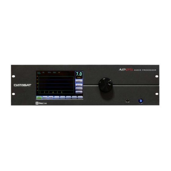
Figure 1: Front Panel Controls and Indicators The front panel contains the following controls and indicators for operating AP25. Power button: Push button switch puts the AP25 in and out of standby power mode. LCD/Touch Screen: Displays theater system configuration and status and allows configuration changes. - Page 16 1.3 Powering ON the AP25 Processor The main power switch for the AP25 is located on the rear panel. A “hard boot” (cycling the power at the power entry module on the rear panel) typically takes the system one minute to initialize. When the main power switch is on, the AP25 can be switched in and out of standby power mode by the pushbutton power switch on the front panel.
-
Page 17: Navigating Through The Menus
Navigating through the Menus Since the AP25 is equipped with a touch screen display, you can navigate easily through the menus by touching any button with your finger. A non-abrasive stylus, that will not scratch the screen, may also be used. -
Page 18: Adjusting The Fader
Adjust the fader volume by using the control knob on the front panel. To mute the fader, touch the Mute button. The button label will turn red and change to “Muted”. Unmute the AP25 by touching the mute button again, or changing formats. If in the Home Screen, increasing the fader volume using the control knob will also unmute. -
Page 19: Booth Monitor Volume
Page 19 1.4.2 Booth Monitor Volume When an external powered speaker is connected to the AP25, the level can be controlled using the monitor volume. To adjust the booth monitor volume, touch the Monitor button. The screen shown in Figure 7 will appear. Touch the + or – buttons to raise or lower the volume. -
Page 20: Troubleshooting (Operation)
AC outlet protected by a surge protector. See Powering ON the AP25 Processor, page 16. If the AP25 is mounted in a rack and a breaker is used for the rack, make sure the breaker is ON. -
Page 21: Over Temperature Alert
AP25 chassis. Check that there is nothing obstructing these air vents. Be sure that the fan is spinning (you will feel air blowing out of the AP25 from the fan). If the vents are clear and the fan is spinning, yet the temperature alert does not stop, call Datasat Technical Service or your technician. -
Page 22: Part 2: Installation And Setup
AP25 Installation and Operating Guide Page 22 Part 2: Installation and Setup This part of this manual contains information the theater technician needs to set up and configure the AP25 Audio Processor. PART 2: INSTALLATION AND SETUP INSTALLATION AND SET UP... - Page 23 AP25 Installation and Operating Guide Page 23 4.2.1 SSIGN ADER EVEL TO A ORMAT 4.2.2 AP25 S PDATING OFTWARE 4.2.3 AVING AND ESTORING ONFIGURATION ILES 4.2.4 CCESS ONTROL 4.2.5 4.2.6 YSTEM 4.2.7 ERSION ERIAL UMBER ADDRESS 4.2.8 YSTEM ONITOR ORMATS 4.3.1...
-
Page 24: Installation Checklist
AP25 Installation and Operating Guide Page 24 Installation and Set Up 2.1 Installation Checklist This checklist summarizes the installation and setup procedures for the AP25. Table 3: AP25 Installation and Setup Completed Task Description Refer to: Install AP25 in Equipment Rack... -
Page 25: Unpacking System Components
Page 25 2.2 Unpacking System Components See the list of standard components for an AP25 shipment, on page 11. The exact contents may vary, depending on the options you have ordered. Note: Refer to the actual packing slip from your order to verify the contents of your shipment. - Page 26 When using the Digital Out, make sure the input device is set to the same sample frequency as the AP25 and that it’s clock source is set to input. Sample rate choices are 48kHz, 96kHz, and 192kHz. Select the highest rate supported.
-
Page 27: Rack Mount Recommendations
(usually to scroll through a list or to increase/decrease values): Note: When using a laptop to VNC into the AP25, use the up and down arrows to mimic the scrolling action of the front panel adjustment knob. - Page 28 The buttons along the bottom of the AP25 Home screen show the default formats or formats that have been created by the installation technician for a particular application. Each format consists of a set of discrete settings: an Input Source, Format Options, EQ settings, and Channel Profile, as illustrated below (Figure 12).
- Page 29 AP25 Installation and Operating Guide Page 29 Figure 12. Global Settings and Format Discrete Settings AP25 Installation & Operating Guide Document # 9301H79500 Ver. 1.00...
- Page 30 AP25 Installation and Operating Guide Page 30 In the Audio Format Setup screen, five options appear along the bottom: Input Source, Format Options, Audio EQ Setup, Channel Profile, and Audio Levels. Menu (System) > Formats Figure 13. Audio Format Setup Screen 2.7.1 Creating an Audio Format...
-
Page 31: Factory Presets
Third Octave EQ: Calibrated adjustment made by qualified technician Parametric Equalization: Calibrated adjustment made by qualified technician 2.8 Factory Presets The AP25 factory settings include formats for Digital Cinema and Nonsync as described in the table below. Table 5. AP25 Factory Presets... - Page 32 AP25 Installation and Operating Guide Page 32 Table 6. AP25 Preset Formats Name Source Digital Cinema Digital In (1-16) HDMI 1 HDMI Port 1 HDMI 2 HDMI Port 2 HDMI 3 HDMI Port 3 HDMI 4 HDMI Port 4 Nonsync1...
-
Page 33: Equipment Requirements
EQ. The laptop computer must be connected to the Ethernet port of the AP25 in order to take advantage of the remote operation feature. You can use a wireless router (not supplied by Datasat) such as the Linksys WRT54GL or a router with a network cable for this connection. - Page 34 The laptop computer uses a Virtual Network Connection (VNC) to communicate with the AP25. The front panel touch-screen display of the AP25 will appear on the laptop screen, but will not function as a touch-screen. Use the laptop’s cursor and arrow keys to make selections.
- Page 35 AP25 Installation and Operating Guide Page 35 Figure 14. Channel Names Screen When channel assignments are complete, you can eliminate the unassigned channels so they do not appear on the main screen. Turn off the Vu indicator for unused channels.
- Page 36 2.9.6 Verify Channel Assignments in Auditorium On the AP25, select a channel and turn on Pink Noise. In the auditorium, verify that the Pink Noise output is coming from the correct loudspeaker(s). Do this for all channels. For details, see Audio Levels, page 93.
- Page 37 AP25 Installation and Operating Guide Page 37 Caution: Before proceeding with the room equalization, it is imperative that the loudspeaker and crossover systems be properly aligned. Issues like speaker phasing and horn tilt need to be checked. When using crossovers the low, mid and high frequency drivers must be balanced to produce a relatively even response from 100 Hz to 5 Hz.
-
Page 38: Set Levels To Establish A Baseline
* Subwoofer should be set to 10 dB of in-band gain (see SMPTE RP-200), which equates to approximately 91 dBC (slow). If not possible to achieve the baseline, use the AP25 (Analog Output Levels) to make minor adjustments. AP25 Installation & Operating Guide... - Page 39 If using Dirac Live, please refer to the Dirac Live Theater Setup manual. For an overview, see Using Dirac Live® to Tune the Auditorium, page 43. The AP25 contains a full suite of 1/3 Octave EQ filters that are “traditional” cinema processor filters. If using AP25 1/3 Octave EQ, complete the following steps.
- Page 40 AP25 Installation and Operating Guide Page 40 5. Turn on XCurve Display. Try to tune the frequency pattern to the XCurve. If the pattern does not conform – there is a hole or a peak or other variance – then select the frequency that needs adjusting, and push it down or pull it up.
-
Page 41: Subwoofer Eq - Parametric Eq
2.11 Subwoofer EQ – Parametric EQ The AP25 features Parametric EQ on every channel. Parametric EQ is an optional adjustment and is in addition to 1/3 Octave EQ. It is only available with low frequencies and offers more control than 1/3 Octave EQ. -
Page 42: Copy Eq Set To Another Eq Set
AP25 Installation and Operating Guide Page 42 Figure 20. Parametric EQ Screen, Filter Enabled 2.12 Copy EQ Set to Another EQ Set This screen is used to copy the EQ settings for all channels to a new EQ set under a new name. After equalizing all the channels, copy these settings to create another EQ (with a new name). - Page 43 To do this, save the setup configuration on a memory stick (USB Flash drive), then use the saved setup to copy to the AP25 for the next screen, since many or all the values will be the same. Menu (System) > USB Save/Restore > Save on USB > Master Configuration See Saving and Restoring Configuration Files, page 56 for more details.
-
Page 44: How-To Procedures For Setup
For digital cinema format, see HDMI Options, page 76 View AP25 System information See 4.2.5 System Info, page 59. Update AP25 software See 4.2.2 Updating AP25 Software, page 54. 3.1 Example: Creating a Format Prior to creating a format, it is necessary to identify the following: Input source... -
Page 45: Setup Menus
Setup Menus On the next five pages, you will find a menu diagram for the AP25. This chapter contains a detailed description of all the screens under the "Menu" selection of the home page. Refer to section 1.4 for all operations under the "Home"... - Page 46 AP25 Installation and Operating Guide Page 46 AP25 Installation & Operating Guide Document # 9301H79500 Ver. 1.00...
- Page 47 AP25 Installation and Operating Guide Page 47 AP25 Installation & Operating Guide Document # 9301H79500 Ver. 1.00...
- Page 48 AP25 Installation and Operating Guide Page 48 AP25 Installation & Operating Guide Document # 9301H79500 Ver. 1.00...
- Page 49 AP25 Installation and Operating Guide Page 49 AP25 Installation & Operating Guide Document # 9301H79500 Ver. 1.00...
- Page 50 AP25 Installation and Operating Guide Page 50 AP25 Installation & Operating Guide Document # 9301H79500 Ver. 1.00...
-
Page 51: The Menu Button
Selecting the button, after first powering up the AP25, will display the System Setup screen. This will provide access to the Setup menus. In the next section, we will discuss in detail the options available through the menu bar. Pressing the Home button will take you back to the Home or Main screen. - Page 52 AP25 Installation and Operating Guide Page 52 Digital Out ClockRate – When interfacing with external digital equipment select appropriate clock rate to match that equipment. Select from the following options: 48 kHz 96 kHz 192 kHz Output Mapping – Channels 9-16: Ch 9-16 Out Normal –...
- Page 53 AP25 Installation and Operating Guide Page 53 4.2.1 Assign Fader Level to a Format To assign a specific fader level to a format button, do the following: 1. Select Menu (System), then in the Fader Control pulldown menu select format. Return to the main screen by selecting Home button.
- Page 54 Fmt Fdr setting. 4.2.2 Updating AP25 Software There are two ways you can update your software. Use an internet connection to connect to the servers at Datasat Digital Entertainment to select and install the update. Update from a USB Device.
- Page 55 The current version of software loaded on the AP25 is displayed under Current on the right side of the screen. The highlighted software version, will display under Selected on the right side of the screen.
- Page 56 AP25 will not recognize it. 3. Insert the USB drive into the USB slot on the front panel of the AP25, choose Select Update Source > USB (see Figure 27), select the update file and press the Start Update button.
- Page 57 Save Master Save AP25 configuration to USB device as a MASTER configuration which Configuration may be loaded onto other AP25 units. This will erase from the USB device any existing MASTER configuration. Save Diagnostic Save AP25 Diagnostic information to the USB device to facilitate Information troubleshooting.
-
Page 58: Access Control
Note: When removing password protection, if no hyphen is entered (blank selection), the AP25 will continue to ask for a password to enter the setup menus. In that case select the OK button to enter the setup menus without entering a password. - Page 59 AP25 Installation and Operating Guide Page 59 Use the hyphen - key to remove password protection. Figure 31. Net Command Virtual Keyboard 4.2.5 System Info From the system Setup screen, touch the System Info button. The System Info screens are shown below.
-
Page 60: System Monitor
4.2.8.1 Monitor-out tracks fader 4.2.8.2 “Expert” Nav Mode When “Expert” Navigation Mode is enabled, the normal AP25 menu structure is replaced with a setup screen that provides quick access to the main menu buttons. After enabling, the new screen appears when the “System” button is pressed. It must be disabled to return to the normal menu structure. - Page 61 The log file (shown in Figure 35, below) is a complete listing of all software events that have taken place since the AP25 was last powered on. The listing includes changes made internally by the AP25 software, as well as user initiated system changes through the touch screen interface. You may scroll through the log file using the front panel adjustment knob.
-
Page 62: Feature Key
Selecting the feature key will bring up a keyboard screen to enter the code. 4.2.8.6 Identity Three text fields can be entered into the AP25 to be used for identification. These are labeled “Screen”, “Theater”, and “Circuit”. The text entered in the “Screen” field will be displayed in the bottom left corner of the home screen above the navigation menu. -
Page 63: Startup Format
Figure 37. Select Current Audio Format 4.3.2 Startup Format The Startup format is the default format selection when the AP25 is powered up. Select any defined format or Last Format. Touch the dropdown list to open it, then select the format. - Page 64 Press the Copy button to complete the process, or press Cancel to quit. Copy Preset to Format – Select one of the pre-installed audio formats in your AP25 and use it as a template for a new one. Select the format you wish to copy from by selecting it from the dropdown box.
-
Page 65: Assign Format Buttons
AP25 Installation and Operating Guide Page 65 4.3.4 Assign Format Buttons Menu (System) > Formats > Assign Buttons Figure 40. Format Button Assignments Screen Touch the Assign dropdown list to open it, then select a format. Touch the to (button) dropdown list to open it, then select a button number. - Page 66 AP25 Installation and Operating Guide Page 66 Button location 5 Button location 8 Figure 41. Home Screen Format Button Locations 4.3.4.1 Enable “More” Button Selecting the Enable “More” Button from the Format Button Assignment screen allows access to more than the eight format buttons normally available on the Home screen. When the Enable “More”...
-
Page 67: Input Source
Decoder appears for input selections Digital 1,2; Digital 9,10; TosLink A & B; S/PDIF; and HDMI 1-4. See Table 13 (below) for a description of where input channels will be routed within the AP25. Figure 43. Input Source Screen AP25 Installation & Operating Guide... - Page 68 If a Dolby Digital bitstream is detected and decoded, the decoded stream will be routed to the first eight channels internally on the AP25. See section 4.3.6.6 Decoder Setup for more information. AP25 Installation & Operating Guide Document # 9301H79500 Ver. 1.00...
-
Page 69: Format Options
AP25 Installation and Operating Guide Page 69 4.3.6 Format Options The Format Options screen allows changes to Global Delay, Extended Surround Options, Nonsync Level and Routing, Mic Level and Routing, Matrix and Routing, Digital Cinema Format Options, Decoder Setup and Film Options (if the optional Optical Film card (H338) is installed – see appendix F). It also provides feedback on the current Audio format. - Page 70 Subtract surround distance from the screen distance, and add 20 (screen - surround + 20). The result is the surround delay in milliseconds. After setting the surround delay in the AP25, verify the setting by listening to a familiar soundtrack. The action on-screen should match sound in the auditorium.
- Page 71 AP25 Installation and Operating Guide Page 71 4.3.6.2 Extended Surround Options This screen is available for input source Analog 8ch. Menu (System) > Formats > Format Options > Extended Surround Options Figure 46. Extended Surround Options None – No surround option, signals are not re-routed.
- Page 72 AP25 Installation and Operating Guide Page 72 Copy surround channels to rear surround channels – Allows the surround channels to be copied to the Rear Surround channels (Ch7 and Ch8) 4.3.6.3 NonSync Level and Routing This screen is available for Nonsync 1 or 2 input sources only.
- Page 73 RTA. Select an optical format on the AP25, enable pink noise on the center channel, and note the level and low frequency roll off displayed on the RTA. Select the appropriate Low Pass Filter setting by pressing that button and using the fader knob to make any changes required to match the low pass filter to the roll off measured.
- Page 74 AP25 Installation and Operating Guide Page 74 4.3.6.3.2. Nonsync Mic Level and Routing System > Formats > Format Options > Nonsync Level and Routing > Mic Figure 50. Mic Level with Nonsync If Enable Mic is selected in the Nonsync level and routing screen, you can adjust mic level and routing by going to Mic Level and Routing screen.
- Page 75 5.1 DCP – Digital In mapping is straight through to the AP25 channels Out. DCP includes HI – Select to route DCP HI In on pin 7 to the AP25 RCA jack. If disabled, HI Out is mixed from DCP In L, R, C.
-
Page 76: Decoder Setup
Note: In this mode the surround Offset should be adjusted down by typically 2dB to achieve proper surround level. DCP includes HI – Select to route DCP HI In on pin 7 to the AP25 RCA jack. If disabled, HI Out is mixed from DCP In L, R, C. -
Page 77: Decoder Setup Options
If an un-encoded digital signal is received (i.e. 2-channel PCM), the signal is routed to the first two channels in the AP25 (Left and Right) and the others remain muted. The HDMI also supports 6 or 8 channel un-encoded PCM signal. The AP25 will switch between stream types as the signal type changes. -
Page 78: Speaker Config
AP25 Installation and Operating Guide Page 78 Speaker Config 5.1 – 6.1 and 7.1 content is mapped to a 5.1 speaker configuration and 5.1 content is unmodified. 7.1 –5.1 and 6.1 content is mapped to a 7.1 speaker configuration and 7.1 content is unmodified. - Page 79 AP25 Installation and Operating Guide Page 79 4.3.7.1 Current Audio EQ This drop-down list allows you to select from the list of available EQ setups. The selection will become the current audio equalization setup. 4.3.7.2 Edit EQs Selecting the Edit EQs button from the Audio EQ Setup screen will open the screen below.
- Page 80 The Dirac Optimization button only appears if the DiracLive option is installed. The Dirac Live setup procedure must be used to copy Dirac configuration filter set files to the AP25 before this screen becomes functional. Menu (System) > Formats > Audio EQ Setup > Dirac Optimization...
- Page 81 AP25 Installation and Operating Guide Page 81 Third Octave EQ Selecting the Third Octave EQ button from the EQ Setup screen will bring up a screen similar to that shown below. See the topic A note about Third Octave EQ in section 2.10 for a usage example.
- Page 82 (5 to 30 seconds). Select times from dropdown lists. The averaging settings (for continuous or manual times) are persistent – the values are retained when the AP25 is cycled off/on. Manual averaging can also be started by touching the RTA screen.
-
Page 83: Parametric Equalization
If Mic Power is ON, it remains ON when you leave this screen and go to other screens. However, Mic Power is automatically disabled when the AP25 resets. This Mic Power setting is independent of the Mic power that is part of Format. - Page 84 AP25 Installation and Operating Guide Page 84 Clear EQ on selected channel includes two check boxes to enable which settings are included in the clear function (1) third octave EQ including bass and treble and/or (2) parametric filters. The text on the right will reflect the selection on the left. Select the channel using the dropdown list, then touch Clear to complete the process.
- Page 85 AP25 Installation and Operating Guide Page 85 4.3.8 Channel Profile Menu (System) > Formats > Channel Profile Figure 63. Channel Profile Setup Screen 4.3.8.1 Current Channel Profile The current channel profile is displayed in the drop-down box under the label “Current Channel Profile”.
-
Page 86: Channel Names
Press the Delete button to complete the process, or press Cancel to quit. 4.3.8.3 Channel Names Depending how the AP25 is connected, sixteen channels are available. Channel assignments can be different in other profiles. The top title bar displays the current format and profile. -
Page 87: Signal Flow
4.3.8.4.1. Signal flow When implementing crossovers or implementing different internal routing on the AP25, the input channel numbers do not match the output channel numbers. The following explanation clarifies how the menus operate regarding the channel numbers. - Page 88 AP25 Installation and Operating Guide Page 88 4.3.8.4.2. High Pass and Low Pass Shelf The High Pass and Low Pass Shelves are for active crossover systems. The High Pass is the portion of the sound spectrum that is going to find its way to the top-end compression driver.
- Page 89 M, H, and 0-9. This is used for reference for the output channel and has no functional purpose at this time. 4.3.8.4.4. Example Crossover Setup When setting up the AP25 crossovers, you will need to identify the speaker model used and obtain its technical specifications. Speaker technical specifications can usually be found on the manufacturer’s web site.
- Page 90 AP25 Installation and Operating Guide Page 90 Set the crossover ID for easy identification. Here we set the crossover ID for channel 1 output which identifies it as the low frequency output for channel one (1). This is only a label for easy identification and does not affect the crossover itself.
- Page 91 AP25 Installation and Operating Guide Page 91 As shown in Figure 70, set output channel for the high range driver. Make sure the input channel is still set to (or left channel, remember, left = channel 1 in the example).
-
Page 92: Channel Delays
AP25 Installation and Operating Guide Page 92 4.3.8.5 Channel Delays Menu (System) > Formats > Channel Profile > Channel Delays Figure 72. Channel Delays Delays can be set for each of the 16 channels. Touch the Delays box under the desired channel. -
Page 93: Audio Levels
AP25 Installation and Operating Guide Page 93 4.3.9 Audio Levels Menu (System) > Formats > Audio Levels Select channel(s) Figure 73. Audio Levels The Audio Levels screen is used for these functions: Set the levels. You can turn on the pink noise on any single channel to check and adjust the level. - Page 94 (blue). Digital volume should be enabled only if the system is using the digital output on the AP25. Note: Channels 1 through 16 on this screen refer to the input channels. In cases where the input is routed to a different output channel, the control represents only the input channel path.
- Page 95 AP25 Installation and Operating Guide Page 95 4.4 Network Menu (System) > Network Figure 74. Network Screen The Network screen displays the current network mode and IP address. It also displays whether or not the network connection is currently up or down. Use it to change between dynamic and static IP addressing.
-
Page 96: Network Diagnostics
USB stick and then emailed to Datasat Tech Support for help with troubleshooting. Ping Test: Use for testing connectivity of the AP25 with a server. Select a network device address from the dropdown menu. If available, the device address should appear in the box to the right. -
Page 97: Add New Event
AP25 Installation and Operating Guide Page 97 associated with an automation button. Menus to allow the creation of macros are provided. A Macro is a script used to perform multiple actions (see 4.5.2 Macros, page 104). 4.5.1 Events Menu (System) > Automation > Events Figure 78. - Page 98 AP25 Installation and Operating Guide Page 98 Event Type – When an event is first added the event type defaults to “No Event”, this means the event type is not configured and should be replaced with one of the other event types.
- Page 99 AP25 Installation and Operating Guide Page 99 o No Action o Delay – Delay is set in milliseconds with a range of 0-10000ms (10 seconds) in increments of 10 ms. o GPO – Select a GPO to set (GPO 1-20 or Projector) by touching the dropdown menu next to “Set”.
- Page 100 AP25 Installation and Operating Guide Page 100 A subsequent action is defined in a separate Automation Edit Action screen and the option Conditional is selected. Then enter the previously defined variable name and whether it should be TRUE or FALSE before the action is executed.
- Page 101 Figure 84. Automation Edit Event screen – Format Change Serial The AP25 can be configured to allow an external device to send an RS232 command to the AP25, which, when receiving the specified serial command, will then execute any predefined action or macro.
- Page 102 Touch OK when finished, or touch Cancel to cancel this task. Fire Alert Event A Fire Alert event will shut down the AP25 audio and display a popup on the home screen that says “Fire Alert Mode Activated” (as shown below). The AP25 audio and menus are disabled until the unit is reset from the back power button.
-
Page 103: Delete Event
Once a Fire Alert event is programmed it will be seen in the Events screen. From here you can edit or delete the event. Once the Fire Alert Mode is activated, the AP25 must be restarted from the rear panel power switch to reactivate normal operation. If the Fire Alert Mode pop up reappears after the restart, then GPI-6 must still be low. -
Page 104: Add Macro
AP25 Installation and Operating Guide Page 104 4.5.2 Macros The Macros menus allow you to create a script of multiple actions. A Macro may then be assigned to an Event. The menu bar contains an “Events” button to allow easy navigation between the Events screen and the Macros screen when building Macros and assigning them to Events. - Page 105 4.5.2.5 Example: Creating a Power On macro In the Figure 87 below, when the AP25 is powered on, it will automatically run actions in a POWERON macro. The AP25 will pulse GPO-1 (start CD player), switch to NONSYNC format and adjust fader level to 5.0.
-
Page 106: Automation Buttons
AP25 Installation and Operating Guide Page 106 Note: you will not see POWERON in the EVENTS screen. It can only be seen in the Macros screen. 4.5.3 Automation Buttons The Automation Buttons screen shows existing buttons assigned to an Event. Information on the associated event appears below each configured button. -
Page 107: Automation Test Screen
The input indicator turns green when there is a low signal applied to the pin. To verify that the AP25 is properly receiving an input from an external source you would need to make the external device send a low signal on that pin. Then confirm that the signal is received by the AP25 by checking if the corresponding circle turns green. - Page 108 There are four pre-programmed Serial Command Modes that may be selected from the dropdown list: AP25, Panastereo, 6AD, and linked AP25. AP20 (AP25) - Serial automation port can be used for any AP25 serial commands as defined by the AP25 document TM-H392. Additionally, any command defined by a serial event will be processed (see section 4.5.1.1 Automation Edit Event: Serial).
-
Page 109: Maintenance And Troubleshooting
- volume level on both AP25s will be the same o format selection – the selected format will match on both AP25 as long as the format names are the same (note that only the format names must match). - Page 110 Using your finger, double-tap the fader level number displayed in the box at the top right corner on AP25’s touch screen. Once you double-tap, a set of arrows will appear that can be used to adjust the main volume up or down. To increase volume, touch the up pointing arrow. To decrease volume, touch the down pointing arrow.
- Page 111 Figure 94. USB Device Not Found If you encounter this error message, be sure you have inserted a USB device into the AP25. If a device is present, it may be malfunctioning. Replace the USB device with another to see if the problem is resolved.
- Page 112 ************************************************************ insert USB memory stick with AP25 image ************************************************************ To solve this problem, reboot the AP25, making sure nothing is in contact with the touch screen during the boot-up process. AP25 Installation & Operating Guide Document # 9301H79500 Ver. 1.00...
-
Page 113: Appendix A. Connector Pin-Outs
AP25 Installation and Operating Guide Version 1.00 Appendix A. Connector Pin-outs This appendix lists the pin-out of all of the connectors on the back panel of the AP25 Audio Processor. Figure 1. AP25 Rear Panel AUTOMATION GPIO – DB25F Description... - Page 114 AP25 Installation and Operating Guide Version 1.00 CONTROL (RS232)– DB9F Description Data out - TXD Data in - RXD Connected to pin 6 Chassis GND Connected to pin 4 Connected to pin 8 Connected to pin 7 N/C = No connection SERVICE PORT (RS232)–...
- Page 115 AP25 Installation and Operating Guide Version 1.00 HDMI IN 1-4, OUT – HDMI Description HDMI TMDS Data 2 (+) TMDS Data 2 (Shield) TMDS Data 2 (-) TMDS Data 1 (+) TMDS Data 1 (Shield) TMDS Data 1 (-) TMDS Data 0 (+)
- Page 116 AP25 Installation and Operating Guide Version 1.00 DIGITAL AUDIO IN (CH 1 – 8) – DB25F Description Standard Ch Assignment Chassis Ground AES 1/2 - AES 3/4 + C/LFE Chassis Ground AES 5/6 - LS/RS AES 7/8 + LC/RC Chassis Ground...
- Page 117 AP25 Installation and Operating Guide Version 1.00 DIGITAL AUDIO OUT (CH 1 – 8) – DB25M Description Standard Ch Assignment Chassis Ground AES 1/2 - AES 3/4 + C/LFE Chassis Ground AES 5/6 - LS/RS AES 7/8 + LC/RC Chassis Ground...
- Page 118 Ultra Stereo JSD-80 cinema processor. The pin-out also matches the Dolby DMA8. Datasat Digital Entertainment offers a DB25 male to female cable, 3-feet long, for hook-up (P/N 2503004100). If wiring your own cable, the following criteria must be met: 1.
- Page 119 AP25 Installation and Operating Guide Version 1.00 ANALOG AUDIO OUT (CH 9 – 16) DB25M Description ANALOG GND CHANNEL 9 (+) CHANNEL 15 (-) ANALOG GND CHANNEL 11 (+) CHANNEL 16 (-) ANALOG GND CHANNEL 10 (+) ANALOG GND CHANNEL 13 (-)
- Page 120 AP25 Installation and Operating Guide Version 1.00 H338 Optical Film Card Option (Rear panel plug in board). PROJECTOR 1 INPUT (Optional)– DB9F Description LT (+) LT / RT (-) LT/ RT (-) RT (+) LT / RT (-) LT / RT Analog GND...
-
Page 121: Appendix B: Interface Wiring Diagrams
AP25 Installation and Operating Guide Version 1.00 Appendix B: Interface Wiring Diagrams Interface Wiring Diagrams Appendix B: Document #: 9301H79500 Ver. 1.00... - Page 122 AP25 Installation and Operating Guide Version 1.00 Interface Wiring Diagrams Appendix B: Document #: 9301H79500 Ver. 1.00...
- Page 123 AP25 Installation and Operating Guide Version 1.00 Interface Wiring Diagrams Appendix B: Document #: 9301H79500 Ver. 1.00...
- Page 124 AP25 Installation and Operating Guide Version 1.00 Interface Wiring Diagrams Appendix B: Document #: 9301H79500 Ver. 1.00...
- Page 125 AP25 Installation and Operating Guide Version 1.00 Interface Wiring Diagrams Appendix B: Document #: 9301H79500 Ver. 1.00...
- Page 126 AP25 Installation and Operating Guide Version 1.00 Interface Wiring Diagrams Appendix B: Document #: 9301H79500 Ver. 1.00...
- Page 127 AP25 Installation and Operating Guide Version 1.00 Interface Wiring Diagrams Appendix B: Document #: 9301H79500 Ver. 1.00...
- Page 128 AP25 Installation and Operating Guide Version 1.00 Interface Wiring Diagrams Appendix B: Document #: 9301H79500 Ver. 1.00...
-
Page 129: Appendix C: Ap25 Wiring And Block Diagrams
AP25 Installation and Operating Guide Version 1.00 Appendix C: AP25 Wiring and Block Diagrams thru 3 HDMI 2.0 Dolby/DTS Decoder Appendix C: Block Diagrams Document #: 9301H79500 Ver. 1.00... -
Page 130: Appendix D: Ap25 Product Specifications
AP25 Installation and Operating Guide Version 1.00 Appendix D: AP25 Product Specifications Digital Audio Decoders Dolby Dolby AC3 DTS-HD Master Audio / DTS ES / DTS 5.1 / Neo:6 Signal Inputs Digital Audio Inputs Channels: 16 Connectors: Two DB25 Female (Ch1-8 and 9-16) Digital Format: AES/EBU Sample Rates: 44.1kHz, 48kHz, 96 kHz and 192kHz... -
Page 131: Signal Outputs
AP25 Installation and Operating Guide Version 1.00 Signal Outputs Digital Audio Outputs Channels: 16, fully routable as to input Connectors: Two DB25 Male (Ch1-8 and 9-16) Digital Format: AES/EBU Sample Rates: 48kHz, 96 kHz and 192kHz Analog Audio Outputs Channels: 16 (fully routable as to input), common mapping with Digital Outputs... - Page 132 AP25 Installation and Operating Guide Version 1.00 Audio Delays Individual Channel Delays Input delay 0 - 999ms Output delay 0-120ms Global Delay 0 –1000ms Note: Total delay per channel not to exceed 1000ms 35mm Film Optical Soundtrack Audio Processing (with optional H338 PCB) Built-in processing for mono, A-Type and SR noise reduction.
-
Page 133: Power Requirements
AP25 Installation and Operating Guide Version 1.00 Power Requirements 100-240 VAC, 50-60Hz, auto-switching 60w power consumption Hardware Dimensions 3U 19” rackmount standard Imperial - 5.25” (H) x 19.0” (W) x 15.0” (D) Shipping Weight: 30lbs Metric - 13.33 cm (H) x 48.25 cm (W) x 38.1 cm (D) Shipping Weight: 13.6kg... -
Page 134: Appendix E: 8-Channel Ap25 Version And H332 Upgrade
MD10H78500) with the exception of Digital Audio channels 9-16 in and out, and Analog Audio channels 9-16 out. The 8 channel AP25 may be upgraded to 16 channels by adding the H332 circuit card (P/N 9030H33200). See page AP25 8-Channel Screens The following screens differ from the standard 16-channel version. - Page 135 AP25 Installation and Operating Guide Version 1.00 System Information Screen Figure 3 – System Info Screen Menu (System) → System Info The System Info screen will display 8Chan. Routing/Crossovers Figure 4 – Routing/Crossovers Screen Menu (System) → Formats → Channel Profile → Routing/Crossovers Channel selection is limited to 8 channels.
- Page 136 AP25 Installation and Operating Guide Version 1.00 Figure 5 – Channel Names Screen Menu (System) → Formats → Channel Profile → Channel Names Channel selection is limited to 8 channels. Channel Delay Screen Figure 6 – Channel Delays Screen Menu (System) → Formats → Channel Profile → Channel Delays Channel selection is limited to 8 channels.
- Page 137 AP25 Installation and Operating Guide Version 1.00 Format Source Selection Screen Figure 7 – Input Select Screen Menu (System) → Formats → Input Source Only the Digital Ch 1-8 and Digital Ch: 1, 2 selections are available. Pressing the Digital button will not toggle to other choices.
- Page 138 AP25 Installation and Operating Guide Version 1.00 Octave EQ Screen Figure 9 – Third Octave EQ Menu (System) → Formats → Audio EQ Setup → Third Octave EQ Channel selection is limited to 8 channels. Parametric EQ Screen Figure 10 – Parametric EQ Menu (System) →...
- Page 139 AP25 Installation and Operating Guide Version 1.00 16-Channel Upgrade (H332 Card) The 8 channel AP25 may be upgraded to 16 channels by adding the H332 circuit card. Order P/N 9030H33200 latest version. H332 Card Installation Tools required: Phillips head #2 screw driver Caution: The H332 card contains parts that are static sensitive.
-
Page 140: Appendix F: Optical Film Card Option
This card offers two inputs (Projector 1 & 2), see Figure 1 below. Both inputs have an LED to indicate which input is active. The automation in the AP25 must be programmed to switch the inputs at the proper time. In addition to these inputs, there are two Lt/Rt test points. These are BNC type connectors that are used for alignment of the projectors optics. - Page 141 6 channel assignments and trim values flat. If the H338 card is not factory installed, Optical formats must be created in the AP25 before the H338 can be used. The optical format must have the analog input source selected as Optical. The H338 card supports standard optical film soundtrack formats: Mono, A-type and SR-type.
- Page 142 AP25 Installation and Operating Guide Version 1.00 Create Optical Formats To create an optical format, copy an existing format. Go to: Menu (System) → Formats → Edit Formats Figure 3– Copy Audio Format Press the Copy Format button. Select a format from the drop down menu of Copy Format From (in Figure 3, above, “DCin” is...
-
Page 143: Input Source Selection
AP25 Installation and Operating Guide Version 1.00 To assign a format button, go to: Menu (System) → Formats → Assign Buttons Figure 5 – Format Button Assignment Select a Format to assign from the Assign drop down menu. Select a button to assign the format to from the drop down menu. - Page 144 Inputs from the film are on the left. The resulting channels are on the right side, and are internal to the AP25. Note that these are not necessarily the output channels as they and may be routed on the AP25 output (see Section 2.9.4 Assign Channels on AP25 in this manual).
- Page 145 AP25 Installation and Operating Guide Version 1.00 In this example, left total (LT) and right total (RT) are the inputs. Output is: 3C = channel 3 is center (your only audio out which is the sum of left total and right total). Notice Matrix and OBE are not available for Mono.
- Page 146 LED voltage and adjust it if necessary, as per the manufacturer’s recommended procedure. F4.3. Wiring and Connections Projector 1 & 2 inputs on the AP25 are 9-pin female D-connectors. See Figure 8 below for pin assignments. Input from the solar cell is a 9-pin Male D-connector. PIN NO.
- Page 147 The right channel is nearest the edge of the film. To confirm proper wiring, while observing the projector output on a RTA or the AP25 setup screen, place a business card or similar object to block the side of the cell nearest the edge of the film. You should detect a large drop in the right channel level.
- Page 148 Allen/Hex Wrenches, small screw driver etc. On the AP25 select one of the optical formats in the home screen, next select Menu (System) → Formats → Format Options → Film Options → Film Setup. You should now be in the Film Card Setup screen as shown in .
- Page 149 Consult your projector’s manual for more information. To close this window, press Dismiss. To manually adjust levels, select the button below the left input level bar and use the AP25 front panel adjustment knob to increase or decrease this level until it meets the reference line.
- Page 150 Figure 14 – Crosstalk using Cat 97 test film Note: while running the CAT 97 test film you can also select Azimuth in the AP25’s optical set up screen. If alignment is correct you should be able to observe a cross on the screen as shown in Figure 15.
- Page 151 Correct Figure 16 – Azimuth This can also be viewed on the AP25 screen by going to Menu (System) → Formats → Format Options → Film Options → Film Setup and Selecting Azimuth (see Figure 15). When Azimuth is selected, on the right a pictorial of the azimuth adjustment is shown.
- Page 152 AP25 Installation and Operating Guide Version 1.00 Figure 17 – Focus After the flattest response is achieved by adjusting the projector optics, the final slit loss correction is made using the Parametric Filter Settings, see Figure 18. F4.4.5. Slit Loss EQ When Slit Loss EQ is selected a graph of the slit loss adjustment is shown on the right of the screen (see Figure 18 below).
- Page 153 Soundtrack Input Figure 19 – Digital Soundtrack Input None is use when the AP25 analog and digital input connectors are not used for the film digital soundtrack. Digital Channels 1->8 select this if the film digital soundtrack player is connected to the AP25 Digital Input channels 1-8 connector.
- Page 154 RTA. Select an optical format on the AP25, enable pink noise on the center channel, and note the level and low frequency roll off displayed on the RTA. Select the appropriate Low Pass Filter Appendix F.
- Page 155 Next turn on the subwoofer channel, enable pink noise on the LFE channel, and then select the Bass Gain by pressing the <Gain> button. Use the AP25 fader knob, or up and down keys when using a laptop, to adjust the Bass Gain to match the Center channel level previously noted on the RTA display.
-
Page 156: Appendix G: Connecting Two Ap25 Units
Version 1.00 Appendix G: Connecting Two AP25 units Two AP25 units can be linked together serially. When this is done the two units work in unison locking their format, fader level, and mute selection. Both AP25 units must have matching format names. The names must match exactly although their format profiles may be different. -
Page 157: Appendix H: Ap25 Remote Command Api
Ethernet connection to AP25 The RJ45 connector labeled Ethernet on the back of the AP25 can be connected to a network switch or router. Once the network parameters are properly set the IP addresses for the AP25 can be found in the Network screen in the IP Address box. - Page 158 Authentication Command The AUTH command must be sent to the AP25 before sending a password protected command. If this is not done, then the command results in no action and the AP25 returns the string “SECERR”. Sending the correct password enables all network commands for the password level for as long as the network connection is maintained.
- Page 159 Command: @IDENTIFY<cr> Operation Response: Read AP20<space> [IP]<space> [Circuit]<space> [Theater]<space> [Screen]<cr> Parameters Confirms AP25 is connected at this address AP20 IP address (useful after broadcast command) [IP] Circuit information [Circuit] Theater information [Theater] Screen information [Screen] 3. Health Enquiry for system health data.
- Page 160 AP25 Installation and Operating Guide Version 1.00 t3: H335 board temperature Example response: HEALTH TEMPERATURE 34,29,25 H331VOLTS Returns voltages sensed on H331 board, <vok>,<ref>,<5v>,<+15v>,<-15v>,<-5V> Example response: HEALTH H331VOLTS 1,3.18,4.99,15.0,-15.0-,-5.0 <vok> is 1 if voltages are all within limits, else 0...
- Page 161 AP25 Installation and Operating Guide Version 1.00 4. Board Information Operation Command: @BOARDINFO<cr> Response: Read H331,[ID],[AD],[R],[V],[CS],[FW],[FCS], H332,[ID],[AD],[R],[V],[CS],[FW],[FCS], H335,[ID],[AD],[R],[V],[CS],[FW],[FCS], H337In,[ID],[AD],[R],[V],[CS],[FW],[FCS], H337Out,[ID],[AD],[R],[V],[CS],[FW],[FCS], H338,[ID],[AD],[R],[V],[CS],[FW],[FCS], HDMI,[ID],[AD],[R],[V],[CS],[FW],[FCS], <cr> Returns a list of boards, present and their hardware and PIC f/w versions. Arguments None Board IDs:...
- Page 162 TCP/IP connection. There are two levels of password protection in the AP25. Both levels are set in the System > Access Control screen on the AP25. The top password labeled NetCmd Password will allow access to the AP25 for Operator level type commands.
- Page 163 7. MAC Address Command: @MAC<CR> Operation Response: Read MAC<space>[Mac adr]<CR> Reads the AP25 or AP25 network MAC address. Parameters This is the 12 digit AP25 network interface MAC address. [Mac adr] Example Send: MAC 080077124578 Receive: Format Commands 8. Format Selection Command: @FORMAT<space>[New Format]<CR>...
- Page 164 @RUNMACRO<space>[Macro]<CR> Operation Response: Write [OK or ERR no macro]<CR> This is used to execute a macro defined in the AP25. Parameters This is the macro name to execute. The name must match exactly the macro [Macro] name on AP25. Note: Spaces may be used within the name.
- Page 165 Send: MUTED 1 Receive: 12. Monitor Level Command: @MONITORLEVEL<space>[New Value]<CR> Operation Response: Read/Write MONITORLEVEL<space>[Value]<CR> Set or read the AP25 monitor level. Parameters [New Value] 0 (minimum) to 100 (maximum). [Value] Current monitor level value. Example MONITORLEVEL MONITORLEVEL 70 Send: MONITORLEVEL 70 Receive: Appendix H.
- Page 166 AP25 Installation and Operating Guide Version 1.00 13. Monitor Mute Command: @MONITORMUTE<space>[New Value]<CR> Operation Response: Read/Write MONITORMUTE<space>[Value]<CR> Set or read the AP25 monitor level. Parameters [New Value] 0 (unmute) or 1 (mute). [Value] Current mutevalue. Example Mute the monitor. MONITORMUTE 1...
- Page 167 * ===================================================================== ** * CONFIDENTIAL: CONTAINS CONFIDENTIAL PROPRIETARY INFORMATION OWNED BY * DATASAT DIGITAL ENTERTAINMENT, INCLUDING BUT NOT LIMITED TO TRADE SECRETS, * KNOW-HOW, TECHNICAL AND BUSINESS INFORMATION. UNAUTHORIZED DISCLOSURE IS A * VIOLATION OF STATE, FEDERAL, AND INTERNATIONAL LAWS.
- Page 168 AP25 Installation and Operating Guide Version 1.00 /* ======================================================================== ** Prototypes * ======================================================================== */ int AP20Command( char *strAp20_IpAddress, char *StrCmd, char *StrPassword ); int Send( int fd , char *StrCmd ); int ReadResponse( int fd , char *StrCmd ); /* ======================================================================== **...
- Page 169 AP25 Installation and Operating Guide Version 1.00 printf("connect() fail\n"); close( fd ); fd = -1; return -1; printf( "Connection to %s:%d OK\n", strAp20_IpAddress, AP20_PORT_NUM ); // Send passord only if AP20 has Setup Password defined char StrAuth[100]; sprintf( StrAuth, "AUTH %s", StrPassword );...
- Page 170 AP25 Installation and Operating Guide Version 1.00 int count=0; for( int i=0; i<RX_BUF_SIZE; i++ ) // read 1-by-1. int ret = read(fd, &c, 1); if ( ret < 0 ) printf( "Count=%d, Error\n", count ); close(fd); fd = -1; if (ret == 1) // add to buffer rxBuf[count++] = c;...
Need help?
Do you have a question about the AP25 and is the answer not in the manual?
Questions and answers