
Related Manuals for Datasat DDR-16 AES67


Summary of Contents for Datasat DDR-16 AES67
- Page 1 DDR-16/32 AES67 Receiver/DAC Installation and Operating Guide Version 0.91 Effective Date: January 2020 Document # 9301H85300 Amplifier Technologies Inc. 1749 Chapin Road, Montebello, CA 90640...
- Page 2 GENERAL SAFETY WARNINGS AND GUIDELINES AVERTISSEMENTS ET DIRECTIVES GÉNÉRALES DE SÉCURITÉ Please Read First CAUTION: To reduce the risk of electrical shock, do not WARNING: To reduce the risk of fire or electric shock, remove the cover (or back). No user serviceable parts inside. do not expose this appliance to rain or moisture.
- Page 3 DDR-16/32 Installation and Operating Guide Page 3 • Cet appareil évacue une chaleur excessive à travers les fentes et les ouvertures du boîtier. Ne bloquez pas et ne couvrez pas ces ouvertures. Assurez-vous que l'appareil est dans une zone ouverte où il peut obtenir un flux d'air suffisant pour éviter la surchauffe.
- Page 4 DDR-16/32 Installation and Operating Guide Page 4 • Cet appareil ne contient aucune pièce réparable par l'utilisateur. N'essayez pas d'ouvrir, de réparer ou de modifier cet appareil. DDR-16/32 Installation & Operating Guide Document # 9301H85300 Ver. 0.91...
- Page 5 Amplifier Technologies Inc. may periodically publish updates and revisions to this publication as it deems necessary. Datasat Digital Entertainment is a wholly owned brand of Amplifier Technologies Inc. All other trademarks are the properties of their respective owners.
- Page 6 éliminer les causes. Limited Warranty Datasat Digital Entertainment software is warranted against defects for a period of 90 days from the date of the original purchase. DDR-16/32 hardware is warranted against defects in material and workmanship for a period of one year from the date of the original purchase.
- Page 7 DDR-16/32 Installation and Operating Guide Page 7 Product Improvements and Upgrades Datasat Digital Entertainment reserves the right to make changes and/or improvements to its products, without notification and without incurring any obligation to incorporate such changes or improvements in products previously sold or shipped.
- Page 8 INCLUDING, WITHOUT LIMITATION, DAMAGES FOR LOSS OF PROFITS, LOSS OF DATA, BUSINESS INTERRUPTION OR ANY OTHER COMMERCIAL DAMAGES OR LOSSES, ARISING OUT OF OR RELATED TO YOUR USE OF THE DATASAT DIGITAL ENTERTAINMENT SOFTWARE OR HARDWARE, HOWEVER CAUSED, REGARDLESS OF THE THEORY OF LIABILITY AND EVEN IF DATASAT DIGITAL ENTERTAINMENT HAS BEEN ADVISED OF THE POSSIBILITY OF SUCH DAMAGES.
-
Page 9: Table Of Contents
The DDR-16/32 is designed to work seamlessly with the Datasat AP25 Audio Processor when the optional H790 AES67 output card is installed. The H790 card supports streaming of up to 16 channels at 96kHz, and 24 channels at 48kHz. -
Page 10: Installation
The packaging is designed to handle normal shipping and handling. Upon receipt of shipment, check for signs of damage before opening and report all damage to the carrier. All shipments made from Datasat Digital Entertainment are customer responsibility once they leave our premises. -
Page 11: Powering On The 1.4 Front Panel Controls
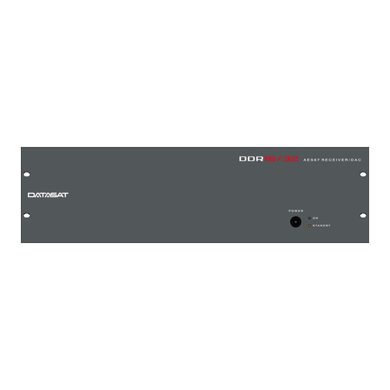
DDR-16/32 Installation and Operating Guide Page 11 1.3 Powering ON the DDR-16/32 The main power switch for the DDR-16/32 is located on the rear panel. A “hard boot” (cycling the power at the power entry module on the rear panel). When the main power switch is on, the DDR-16/32 can be switched in and out of standby power mode using the pushbutton power switch on the front panel. -
Page 12: Pre-Configured Systems
DDR-16/32 Installation and Operating Guide Page 12 Table 1. DDR-16/32 Rear Panel Connections/Controls ITEM DESCRIPTION Power Entry Module/Power Switch USB Audio – Not functional AES67 In – RJ45F (connect to AES67 audio source). Cat-5e or better (Cat-6 preferred). Service Port – DB9 RS232 (used for setup) Ethernet: Status/Control –... -
Page 13: Systems Not Pre-Configured
DDR-16/32 Installation and Operating Guide Page 13 Systems Not Pre-Configured All MDS EQ3-AoIP units are fully tested before shipping, and therefore in the event that audio streaming is not working out of the box, it is likely that the AES67 routing settings have been changed or are incompatible with the current environment, for example the sourcing device name has changed. - Page 14 DDR-16/32 Installation and Operating Guide Page 14 3.1 Troubleshooting Tips In the event the system configuration has been lost or does not match the operating environment, some simple troubleshooting steps could be taken in the field to identify and correct configuration problems. In order to carry out these troubleshooting steps, some supporting equipment and software are needed: 1.
-
Page 15: Connector Pin-Outs
DDR-16/32 Installation and Operating Guide Version 0.91 Appendix A. Connector Pin-outs This appendix lists the pin-out of all of the connectors on the back panel of the DDR-16/32. Figure 1. DDR-16/32 Rear Panel AES67 IN – RJ45F Description TX_D1 (+) TX_D1 (-) RX_D2 (+) Not used... - Page 16 DDR-16/32 Installation and Operating Guide Version 0.91 ANALOG AUDIO OUT (CH 1 – 8) DB25F – TASCAM pinout Description CHANNEL 8 (+) ANALOG GND CHANNEL 7 (-) CHANNEL 6 (+) ANALOG GND CHANNEL 5 (-) CHANNEL 4 (+) ANALOG GND CHANNEL 3 (-) CHANNEL 2 (+) ANALOG GND...
- Page 17 DDR-16/32 Installation and Operating Guide Version 0.91 ANALOG AUDIO OUT (CH 17 – 24) (DDR-32 only) DB25F – TASCAM pinout Description CHANNEL 24 (+) ANALOG GND CHANNEL 23 (-) CHANNEL 22 (+) ANALOG GND CHANNEL 21 (-) CHANNEL 20 (+) ANALOG GND CHANNEL 19 (-) CHANNEL 18 (+)
- Page 18 DDR-16/32 Installation and Operating Guide Version 0.91 Appendix B: DDR-16/32 Product Specifications System Features Modular design AES67 input- up to 24 channels at 48kHz DDR-16 supports 16 channel analog output DDR-32 supports 32 channel analog output Supports bass management Two and three way crossover Linkwitz-Riley or Butterworth filters Filter types: Low Pass...
- Page 19 DDR-16/32 Installation and Operating Guide Version 0.91 Output levels adjusted using volume control chips AC Power Supply Electrical Specification 90-264 VAC, 47-63Hz, auto-switching 60w power consumption Power supply standby power output: 40W Efficiency: greater than 85% Switching frequency: 67kHz typical Conducted EMI EN 55022-B, FCC Part 15 Level B Complies with EN61000-3-2, Class A standard ITE Safety Agency Approvals...
-
Page 20: Ap25 Aes67 Out Card (H790) Setup
Appendix C. AP25 AES67 Out Card (H790) Setup The AP25 AES67 Out card (H790) is a plug in option for the Datasat AP25 audio processor, allowing it to work seamlessly with the DDR-16/32. This appendix describes setup of the H790. The H790 card converts audio channels from the AP25 to AES67 format, allowing streaming over an Ethernet cable. - Page 21 DDR-16/32 Installation and Operating Guide Version 0.91 Ethernet Link This section displays: Ethernet link status (up, down) Current IP address of the AP25 Select the Configure button to bring up the AES67 Network configuration screen. Figure 3 – Network Configuration Screen DHCP is the default selection.
- Page 22 DDR-16/32 Installation and Operating Guide Version 0.91 Figure 5 – PTP Configuration Screen The default is to have the AP25 set as the Preferred Master, but alternatively another device may be chosen. The Domain ID may be configured to any number between 0 and 127. Sending and receiving AES67 devices should be configured with the same PTP Domain ID.
- Page 23 DDR-16/32 Installation and Operating Guide Version 0.91 (D) If AutoConf is selected, the stream will be automatically configured. To manually configure the stream, deselect the AutoConf button. Tap in the gray boxes that appear to bring up a virtual keyboard to enter the multicast address and port. The multicast address is computed from the current IP address of the device as follows: 239.N.AAA.AAA, where N is the stream number and AAA.AAA are the last two bytes of the device’s IP address.
- Page 24 DDR-16/32 Installation and Operating Guide Version 0.91 AES67 Firmware Allows update of the AES67 firmware on the card. Selecting the Update button will bring up the screen shown in Figure 9. The top information box shows the current firmware version, and if another version is available.
Need help?
Do you have a question about the DDR-16 AES67 and is the answer not in the manual?
Questions and answers