Sun Microsystems SPARCserver 1000 Service Manual
Hide thumbs
Also See for SPARCserver 1000:
- Manual (76 pages) ,
- Installation manual (70 pages) ,
- Installation and user manual (28 pages)
Table of Contents
Advertisement
Quick Links
SPARCserver 1000 System Service Manual
Warning – Procedures contained in this manual must be performed by
qualified service-trained maintenance providers.
Refer to the section entitled "Notes, Cautions, and Warnings" found in the
Preface of the front matter of this service manual Binder.
A Sun Microsystems, Inc. Business
2550 Garcia Avenue
Mountain View, CA 94043 U.S.A.
415 960-1300 FAX 415 969-9131
Part No.: 801-2895-15
Revision A, June 1996
Advertisement
Table of Contents

Related Manuals for Sun Microsystems SPARCserver 1000


Summary of Contents for Sun Microsystems SPARCserver 1000
- Page 1 SPARCserver 1000 System Service Manual Warning – Procedures contained in this manual must be performed by qualified service-trained maintenance providers. Refer to the section entitled “Notes, Cautions, and Warnings” found in the Preface of the front matter of this service manual Binder.
- Page 2 Rights in Technical Data and Computer Software clause at DFARS 252.227-7013 and FAR 52.227-19. Sun, Sun Microsystems, the Sun logo, and Solaris are trademarks or registered trademarks of Sun Microsystems, Inc. in the United States and in other countries. All SPARC trademarks are used under license and are trademarks or registered trademarks of SPARC International, Inc. in the United States and in other countries.
- Page 3 Revision History Revision Dash Date Comments 801-2895-15 June 1996 4th Revision to FCS 801-2895-13 October 1994 3rd Revision to FCS 801-2895-12 May 1994 2nd Revision to FCS 801-2895-11 August 1993 1st Revision to FCS 801-2895-10 May 1993 First Customer Ship (FCS)
- Page 4 SPARCserver 1000 System Service Manual—June 1996...
- Page 5 Contents Preface ..........Part 1 —System Information 1.
- Page 6 5.1 Safety Precautions ....... . SPARCserver 1000 System Service Manual—June 1996...
- Page 7 5.2 Tools Required ........6. Powering Off and On ........6.1 Powering Off the System .
- Page 8 10.2 Handling System Boards and Subassemblies ..10-1 10.3 System Board Description ......10-2 viii SPARCserver 1000 System Service Manual—June 1996...
-
Page 9: Table Of Contents
10.4 System Board Block Diagram ..... . . 10-4 11. System Board and Component Replacement ....11-1 11.1 System Board. - Page 10 C. SIMMs and Jumpers........C.1 SIMM Configuration ......SPARCserver 1000 System Service Manual—June 1996...
- Page 11 C.1.1 System Board Rules ......C.1.2 Locating a Failing SIMM ..... . C.2 Jumper Configuration .
- Page 12 Glossary........Glossary-1 SPARCserver 1000 System Service Manual—June 1996...
- Page 13 Figures Figure 1-1 SPARCserver 1000 System ......Figure 1-2 Internal Components ........
- Page 14 Fan Tray ..........SPARCserver 1000 System Service Manual — June 1996...
- Page 15 Figure 8-3 SCSI Tray Assembly ........Figure 8-4 Power Supply .
- Page 16 Serial Port A and B Connector Pinouts ....Figure E-1 System Board Open Boot PROM Location ....SPARCserver 1000 System Service Manual — June 1996...
- Page 17 Figure E-2 SuperSPARC module Locations ......Figure E-3 SBus Card Locations ........Figure E-4 SIMMs and NVSIMM .
- Page 18 SPARCserver 1000 System Service Manual — June 1996...
- Page 19 Tables Table 1-1 Internal Options ........1-10 Table 2-1 Hardware and Software Control of the System .
- Page 20 Example of Connector and Slot Priorities ....Table E-2 Example of SBus Card Distribution ..... . SPARCserver 1000 System Service Manual—June 1996...
- Page 21 This system board manual is written for a trained service provider who intends to service the SPARCserver 1000™ or SPARCserver 1000E™ system. In general, the term SPARCserver 1000 refers to both the SPARCserver 1000 and the SPARCserver 1000E system. Where the SPARCserver 1000E is different, this is explicitly noted.
- Page 22 C shell, Bourne shell, and Korn shell. Table P-2 Shell Prompts Shell Prompt C shell prompt machine_name% C shell superuser prompt machine_name# Bourne shell and Korn shell prompt Bourne shell and Korn shell superuser prompt xxii SPARCserver 1000 System Service Manual—June 1996...
- Page 23 SBus Intelligent SCSI Host Adapter Guide 800-5355 disk card Installation Manual 801-7671 2.1 Gbyte disk card Installation Manual 801-2196 Diagnostics SPARCserver 1000 Open Boot PROM Documentation Set 825-1346 OpenBoot Command Reference 800-6076 OpenBoot Quick Reference 800-5075 User’s Guides SPARCserver 1000 Storage Device User’s Guide 801-2198 SPARCserver 1000 POST User’s Guide...
- Page 24 Ordering Sun Documents SunDocs is a distribution program for Sun Microsystems technical documentation. Easy, convenient ordering and quick delivery is available from SunExpress™. You can find a full listing of available documentation on the World Wide Web: http://www.sun.com/sunexpress/ Country Telephone...
- Page 25 Notes, Cautions, and Warnings Warning – The SuperSPARC module has a hot surface. Avoid contact. Surfaces are hot and may cause personal injury if touched. Warning – This equipment contains lethal voltage. Accidental contact can result in serious injury or death. Warning –...
- Page 26 SPARCserver 1000 System Service Manual—June 1996...
- Page 27 Part 1 — System Information...
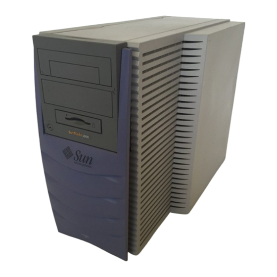
- Page 29 SunCD Plus™ or SunCD 2Plus™ drive • 4 mm DAT tape drive or 8 mm tape drive The SPARCserver 1000 system features an architecture allowing incremental system expansion. The SPARCserver 1000 is a stackable, tabletop unit featuring front and rear component accessibility. See Figure 1-1.
-
Page 30: Figure 1-1 Sparcserver 1000 System
Figure 1-1 SPARCserver 1000 System The internal components of SPARCserver 1000 system, shown in Figure 1-1are: • Power supply • Fan tray • SCSI tray assembly with on-board controller • System board SPARCserver 1000 System Service Manual—June 1996... -
Page 31: Figure 1-2 Internal Components
System board Control board SCSI tray assembly Fan tray Power supply Figure 1-2 Internal Components Product Description... -
Page 32: Figure 1-3 Chassis Assembly
Card guides Backplane Backplane Front Back Figure 1-3 Chassis Assembly The SPARCserver 1000 backplane contains: • 1 XDBus (64-bit data and 1-bit parity) • System monitoring bus • System scan bus SPARCserver 1000 System Service Manual—June 1996... - Page 33 1.1.2 Power Supply The power supply, shown in Figure 1-4, provides 650 watts of power and includes a system maintenance panel with three status LEDs. The power supply plugs directly into the backplane through two 240-pin connectors. Connection to the fan tray is provided through a single connector located on the right rear side of the power supply.
- Page 34 1.1.3 Fan Tray The SPARCserver 1000 fan tray, shown in Figure 1-5, provides cooling for the power supply, system boards, and the SCSI tray assemblies. In addition, this module routes AC power from the chassis rear to the power supply. Each fan has a fail sensor to enable orderly system shutdown if a fan fails.
- Page 35 1.1.4 SCSI Tray Assembly The SCSI tray assembly, shown in Figure 1-6, consists of: • Backup device tray on the left side • SCSI disk drive tray on the right side • Control board on top of the SCSI-2 disk drives The SCSI tray assembly mounts above the power supply in the chassis front.
-
Page 36: Figure 1-7 Sparcserver 1000 System Board
1.1.5 System Board Each SPARCserver 1000 system must have at least one system board. The first board is located in slot 0 of the card cage. The system board contains: • One single-ended narrow SCSI-2 port • 10Base-T Ethernet port •... - Page 37 1.1.6 Options Options add computing power and mass storage capacity to the minimum configuration. System options include: • NVSIMMs • ECC memory (DRAM SIMM) expansion • SBus cards • Disk drives • Tape drive • SuperSPARC modules • Disk card •...
-
Page 38: Internal Options
1.1.8 Internal Options The system contains a card cage with space for up to four boards. Table 1-1 summarizes the internal options for the SPARCserver 1000 system. Table 1-1 Internal Options Option Location Quantity Comments System board Card cage 1-4 per system... - Page 39 Part 2 — Troubleshooting...
- Page 41 Troubleshooting Overview This chapter explains how to determine which hardware or software controls the system during different phases of system operation. 2.1 System Control To troubleshoot a problem, determine which part of the system is in control during the involved phase of operation. When AC power is applied, system control passes in the order below: •...
- Page 42 SPARC module) residing • major, the system cannot in the lowest card cage slot. This is run and the right side often (but not always) slot 0. green LED remains off SPARCserver 1000 System Service Manual—June 1996...
- Page 43 Table 2-1 Hardware and Software Control of the System (Continued) Control Area Actions Observations Indicators OpenBoot The boot program runs additional To read OBP messages, connect System board LEDs: tests such as the disk drive tests. the console (serial ASCII •...
-
Page 44: Figure 2-1 Reset Switch And Status Indicators
On — (when POST completes) hardware failure is detected Right (green) Off — (first 60 seconds of AC power) POST is running On — (after POST completes) system is running Off — (after POST completes) system cannot run; repair needed SPARCserver 1000 System Service Manual—June 1996... -
Page 45: Table 2-3 Indicator Locations
Table 2-3 Indicator Locations Location Access Description System View from rear of Ten LEDs used with POST diagnostics: board(s) system chassis Left 2 LEDs (green) indicate presence of SuperSPARC module A and B. On system master only, right 8 LEDs (yellow) cycle constantly. - Page 46 SPARCserver 1000 System Service Manual—June 1996...
- Page 47 Diagnostics and Commands for Troubleshooting This chapter describes basic troubleshooting procedures. 2.1 Diagnosing Problems 2.1.1 LEDs To determine if a system failure has occurred, look at the front panel LEDs. If the center (yellow) LED is lit, the system has one or more hardware failures. System board LED patterns provide some information about board status.
- Page 48 POST presents several menus to help the user debug failures. For a complete explanation of menus, see the SPARCserver 1000 POST User’s Guide. The menus provide detailed information that may prove more useful in the factory or service depot than in the field.
- Page 49 Below is an example of the command and its output, actual output will differ. Code Example 2-1 The prtdiag Command # ./prtdiag System Configuration: Sun Microsystems sun4d SPARCserver 1000 System clock frequency: nn MHz Memory size: nnnMb Number of XDBuses: 1 ====== CPU Units [MHz] ======== Memory Groups [MB] ============= grp0...
- Page 50 The “ok” prompt displays; proceed to step 3. b. The screen below displays Type b (boot), c (continue), or n (new command mode) > Type the following: > n <return> This yields the “ok” prompt. SPARCserver 1000 System Service Manual—June 1996...
- Page 51 3. Enter the appropriate command to probe the system for SCSI-2 devices. a. To probe all SCSI-2 devices installed in the system: probe-scsi-all <return> b. To confine the probe to SCSI-2 devices hosted by a specific on-board or SBus SCSI-2 host, substitute for variables A and B in the command below, where A is the board number (0-3) and B is the SCSI-2 host;...
- Page 52 This prompt will appear only if: • The system does not recognize any board as the system master. • More than one board is recognized as being qualified to function as the system master. SPARCserver 1000 System Service Manual—June 1996...
- Page 53 Caution – To see the OBP message prompt, the system master board must be connected to a terminal. If the terminal is connected to the wrong board, the message will not appear. The system may seem to be locked up, but OBP is only pausing, waiting for you to respond to the prompt.
- Page 54 POST as master board, a system board must have at least one SuperSPARC module, and must be the first such board located in the card cage. Install any moduleless boards in slots 1 or higher. SPARCserver 1000 System Service Manual—June 1996...
- Page 55 • When swapping system boards in a card cage, remember that the master board must connect with • root disk • system console If the console connects to the wrong system board, you will not see POST and OBP messages. Serial Port A Figure 2-2 TTY Serial Port...
- Page 56 Rest the top of the front panel in the grooved channel on the top panel. Push in on the lower portion of the front panel until it snaps back into place. 3. Return the key to the key switch. 2-10 SPARCserver 1000 System Service Manual—June 1996...
- Page 57 Removing the Front Panel Warning – Once the system is operating, do not move or attempt to move the SPARCserver 1000 with the system power on. Failure to heed this caution may result in catastrophic disk drive failure. Always power the system off completely before attempting a move.
- Page 58 • If the system is in an unknown state, press the following in sequence: system Reset switch (See Figure 2-5) v key s key An example terminal display is shown below. <#2> ok reset Resetting... 1A> *** Toggle Verbose Flag = 1 *** 1A> 2-12 SPARCserver 1000 System Service Manual—June 1996...
- Page 59 *** Toggle Stop POST Flag = 1 *** 1A> DEMON 1A>Select one of the following functions 1A> ‘0’ System Parameters 1A> ‘1’ Read/Write device 1A> ‘2’ Software Reset 1A> ‘3’ NVRAM Management 1A> ‘4’ Error Reporting 1A> ‘5’ Analyze Error Logs 1A>...
- Page 60 POST to gain details about the failure. In the example above, you would connect the terminal the board in slot 0, 1, 2 or 3, then press the reset button to initiate POST. 2-14 SPARCserver 1000 System Service Manual—June 1996...
- Page 61 Table 2-1 describes in more detail the fields in the system status display. Table 2-1 Terms Used in the System Status Display Term Meaning Comment Slot card cage slot number cpuA, cpuB SuperSPARC module slot A or B 0 = module failed 1 = not present Blank = not present bw0, bw1...
- Page 62 0A> ‘0’ Print Bad Group List 0A> ‘1’ Clear Bad Group List 0A> ‘2’ Print Bad Page List 0A> ‘3’ Clear Bad Page List 0A> ‘r’ Return to Main menu 0A> Command ==> 2-16 SPARCserver 1000 System Service Manual—June 1996...
- Page 63 10. To exit the menu, press r to return to the main menu, then press r again to return to the self test. 2.8 Interpreting System Board LEDs If no terminal is present, inspect front panel LEDs for a POST- found problem. Note –...
- Page 64 B slots. See Chapter 11, Section 11.3, “SuperSPARC Modules” for module location and replacement procedure. 2.11 SIMMs and NVSIMMs POST will identify failed SIMMs or NVSIMMs. See Chapter 11, Section 11.5, “SIMMs and NVSIMMs” for location and replacement procedure. 2-18 SPARCserver 1000 System Service Manual—June 1996...
- Page 65 Troubleshooting Flow Diagrams This chapter presents strategies for quickly locating faulty hardware. Use Table 3-1 to locate the flow diagram section that applies to your problem. Table 3-1 Problem Areas Problem Area Flow Diagram Branch Reference Physical system and connections Figure 3-2 Control Board Figure 3-3...
- Page 66 This branch checks the backplane and card cage configuration. Checking the Net Monitoring network integrity uncovers faults in both the physical and application layers. Fault isolation in this branch primarily focuses on the physical medium. Figure 3-1 Troubleshooting Flow Diagram Overview SPARCserver 1000 System Service Manual—June 1996...
- Page 67 Ensure that cables and AC cord are securely connected. Ensure voltage is120-240 Vac. Can POST Ensure SPARCserver 1000 and SPARCserver 1000 systrem boards are diagnostics run? not intermixed in the card cage. Use Sun part numbers to distinguish between the two — refer to Chapter 12. System board types must all match the control board type.
- Page 68 Can POST diagnostics run? Replace control board if necessary. Are status LEDs OK on control board? Are DC LEDs OK on control board? Replace DC power supply if necessary. Figure 3-3 Branch A.1: Control Board SPARCserver 1000 System Service Manual—June 1996...
- Page 69 If the system still does not power up or run, the module(s) may be faulty or not seated properly. Replace the SuperSPARC A module-less system board cannot How many module (in SPARC slot 0) run diagnostics (unless assisted by modules are and attempt power on.
- Page 70 OBP ends and the operating system begins running.If you have a terminal, a message will be displayed. Did self-tests pass? Figure 3-5 Branch B: Power-on Self-test (POST) Functions SPARCserver 1000 System Service Manual—June 1996...
- Page 71 The system failed self-test. A terminal is required to see the failed test. If POST is run in the diagnostic mode, the failing board will loop on the error. The LED pattern should be frozen, except for memory tests. Connect a terminal to the failed board. Initiate POST for more details on the failure.
- Page 72 If the board is not faulty, the problem may be If the self-test fails, swap the SBus card a serial cable, peripheral, modem, or patch and repeat the test. panel. Next, attempt to boot the system. Figure 3-8 Branch B.3: SBus Card Fault SPARCserver 1000 System Service Manual—June 1996...
- Page 73 Monitoring System Start-up After POST passes successfully, there is a display output to the console. At this point, if a TTY terminal is available, you may boot up in DIAG mode and use the Open Boot PROM. The system will attempt to boot from a selected device specified in the boot path.
- Page 74 To test the network, use the OBP command watch-net. Using the OpenBoot PROM, verify the ethernet address by Does system boot? typing the command banner at the ok prompt. Figure 3-10 Branch D: Checking Boot Path and NVRAM 3-10 SPARCserver 1000 System Service Manual—June 1996...
- Page 75 Checking the Network A network problem may be caused by either the physical medium or the application software. Check the network response as the system is initializing or booting over the net. If this is a stand-alone system, see if there is interference from the network. If the system is standalone, the two main indicators of net problems are:...
- Page 76 This path can not assume that the user will have enough UNIX background Boot the client. to fix the OS. The reinstallation serves as an alternative resolution only. Figure 3-13 Branch E.4: Additional Ethernet Messages 3-12 SPARCserver 1000 System Service Manual—June 1996...
- Page 77 Part 3 — Preparing for Service...
- Page 79 Safety and Tools Requirements This chapter covers the procedures and information you need to know before you begin servicing your SPARCserver 1000 system. 5.1 Safety Precautions Caution – Use the Sun ESD kit provided when working on the SPARCserver 1000. This kit contains the Sun approved Sun ESD mat which has cushioning to protect underside components, prevent board flexing, and provide ESD protection.
- Page 80 1. A disposable EDS kit can lose effectiveness after a single use. 5.2 Tools Required Have the following tools available before you begin: • Sun ESD mat and grounding wrist strap • #0 and #1 Phillips screwdriver • Flat-blade screwdriver SPARCserver 1000 System Service Manual—June 1996...
- Page 81 Powering Off and On Use the information in this chapter to power off and on the system. 6.1 Powering Off the System Once the diagnostics are completed, you can remove the TTY terminal. However, do not disconnect the terminal while the system is running. Before turning off the system power, halt the operating system.
- Page 82 5. Turn the key switch on the front panel to the Standby position (fully counterclockwise). See Figure 6-1. Standby Diagnostics Locked Figure 6-1 Key Switch in the Standby Position 6. Turn the AC power switch on the system rear to off. See Figure 6-2. SPARCserver 1000 System Service Manual—June 1996...
-
Page 83: Figure 6-2 Ac Power Switch And Plug
AC power switch AC plug Figure 6-2 AC Power Switch and Plug 6.2 Restarting the System Note – As the system starts up, watch for error messages from the POST diagnostic program. If a terminal is not connected, locate a TTY terminal before continuing the installation. -
Page 84: Figure 6-3 Key Switch In On Position
Key Switch in On Position Warning – Never move the system when the power is on. Failure to heed this warning may result in catastrophic disk drive failure. Always power the system off before moving it. SPARCserver 1000 System Service Manual—June 1996... - Page 85 5. Watch the terminal screen for possible error messages from the POST diagnostic program. POST tests subassemblies in the server and some interface paths between subassemblies. At the conclusion of testing, POST automatically attempts to reconfigure the system, omitting any parts of the system that have failed diagnostics. If there are no faults, or if POST completes a successful reconfiguration of the detected faults, the system boots.
-
Page 86: Figure 6-4 Removing The Front Panel
Removing the Front Panel 2. Insert the back of a pencil or other narrow object into the small opening in the center of the metal face plate and press the reset button. See Figure 6-5. SPARCserver 1000 System Service Manual—June 1996... -
Page 87: Figure 6-5 Reset Switch (Behind The Front Panel) And Front Panel Status Leds
Reset switch Status LEDs Figure 6-5 Reset Switch (Behind the Front Panel) and Front Panel Status LEDs 3. After the system is reset, replace the front plastic panel. Rest the top of the front panel in the grooved channel on the top panel. Push in on the lower portion of the front panel until it snaps back into place. -
Page 88: Table 6-1 Front Panel Led System Status
After POST completes self-test, a message like the following will appear on your screen. The message lists hardware components detected by the system. <<<< SPARCserver 1000 POST V4.1 >>>> ... (various test messages) ... SPARCserver 1000 Series No Keyboard ROM Rev. - Page 89 Part 4 — Subassembly Removal and Replacement...
- Page 91 This chapter provides the information necessary to prepare the system for service after the system has been powered off. To access the SPARCserver 1000 SCSI tray subassembly, the power supply, and the backplane remove the front panel and the EMI shield. To access the other side of the backplane, remove all system boards and air restrictor panels.
-
Page 92: Figure 7-1 Removing The Front Panel
Set the EMI shield aside. See Figure 7-2. Caution – Re-install the EMI shield before operating the system. Sun Microsystems Inc. is not responsible for regulatory compliance for a SPARCserver 1000 System which is operated with the EMI panel removed. SPARCserver 1000 System Service Manual—June 1996... -
Page 93: Figure 7-2 Removing The Emi Shield
Removing the EMI Shield 7.3 Air Restrictor Boards The SPARCserver 1000 can have up to four boards installed. Slots not occupied by functional boards must have air restrictor boards installed. These air restrictor boards must be removed to gain access to the backplane. -
Page 94: Figure 7-3 Removing Air Restrictor Board Retaining Screws
In some cases it may be easier to push the front edge of the side panel toward the chassis rear. See Figure 7-4. Repeat for the other side panel. SPARCserver 1000 System Service Manual—June 1996... -
Page 95: Figure 7-4 Removing The Side Panels
Figure 7-4 Removing the Side Panels 7.5 Top Panel The top panel slides rearward to a release point, then lifts off. Note – You need not remove the top panel to access any system component or subassembly. To remove the top panel: 1. -
Page 96: Figure 7-5 Removing The Popouts From The Top Panel
Note – If necessary, slide your lifting hand side-to-side under the rear lip while tapping the front to free each of the three raised areas on the panel underside of sheet metal cutouts beneath. SPARCserver 1000 System Service Manual—June 1996... -
Page 97: Figure 7-6 Removing The Top Panel
c. Lift the top panel straight up and clear of the chassis. Set it aside. Figure 7-6 Removing the Top Panel Replace the Popouts 4. Replace the popouts in the top panel to avoid their separation and loss: a. Orient the popout so the dots are nearest each other (see Figure 7-7). b. - Page 98 The bottom and top panels are identical part-fabrications and are removed in the same manner. With the chassis inverted and the front facing you, repeat Section 7.5, “Top Panel” step 3 and refer to Figure 7-6 to remove the panel. SPARCserver 1000 System Service Manual—June 1996...
- Page 99 Major Subassemblies The SPARCserver 1000 is a compact server system with the assemblies below: • Fan tray • SCSI tray • Power supply • Backplane Figure 8-1 shows the locations of each assembly in the system unit.
-
Page 100: Figure 8-1 Subassembly Location
AC power switch. 2. Unplug the power cable from the fan tray. 3. Remove the two retaining screws that secure the fan tray to the chassis. Set the screws aside for reinstallation. See Figure 8-2. SPARCserver 1000 System Service Manual—June 1996... - Page 101 AC power switch Pull handle Retaining screws (2) Power cord connector Figure 8-2 Fan Tray 4. Grasp the pull handle. Slowly and firmly slide the tray from the chassis. 8.1.2 Replacement 1. Slide the fan tray into the slot on the left rear side of the chassis until you can hear and feel the connector seat in the power supply connector.
-
Page 102: Figure 1-6 Scsi Tray Assembly
5. Slide the SCSI tray out of the chassis. Warning – The SCSI tray assembly may be heavy. Grip it securely before sliding it all the way out of the chassis or it could fall and injure personnel or equipment. SPARCserver 1000 System Service Manual—June 1996... - Page 103 SPARCserver 1000 System which is operated with the EMI panel removed. 8.3 Power Supply The power supply is located in the lower front of the SPARCserver 1000 system behind the front cover and EMI shield. See Figure 8-1. 8.3.1 Removal 1.
- Page 104 2. When the supply is halfway in, extend the injector/ejector levers out. 3. While holding the injector/ejector levers, slide the power supply into the chassis until the levers engage the metal on the chassis. SPARCserver 1000 System Service Manual—June 1996...
- Page 105 SPARCserver 1000 System which is operated with the EMI panel removed. 8.4 Backplane The backplane is located near the center of the SPARCserver 1000 behind the front cover, EMI shield, SCSI tray, and power supply. See Figure 8-1. 8.4.1 Removal 1.
-
Page 106: Figure 8-6 Removing The Backplane
Backplane Backplane Front Back Figure 8-5 Backplane Retaining screws Figure 8-6 Removing the Backplane SPARCserver 1000 System Service Manual—June 1996... - Page 107 6. Replace the EMI shield and the front panel. Caution – Replace the EMI shield before operating the system. Sun Microsystems Inc. is not responsible for regulatory compliance for a SPARCserver 1000 System which is operated with the EMI panel removed. Major Subassemblies...
- Page 108 8-10 SPARCserver 1000 System Service Manual—June 1996...
- Page 109 This chapter describes the procedures used to remove and replace the storage devices located in the SCSI tray assembly. The SPARCserver 1000 SCSI tray assembly can contain the following devices: • CD-ROM drive: SunCD Plus or SunCD 2Plus or SunCD Plus4 •...
-
Page 110: Figure 9-1 Removing The Mounting Bracket From The Scsi Tray
4. Remove four screws that secure the CD-ROM drive to the bracket. See Figure 9-2. 5. Remove the CD-ROM drive from the 5 1/4-inch device bracket. Note – Slide the drive out from the front if a tape drive is mounted above it. SPARCserver 1000 System Service Manual—June 1996... -
Page 111: Figure 9-2 Removing The Cd-Rom Drive From The Mounting Bracket
Drive mounting screws (4) SunCD 2Plus drive Figure 9-2 Removing the CD-ROM Drive from the Mounting Bracket 9.1.2 Replacement Note – Verify the ID SELECT, PARITY and PREVENT/ALLOW jumpers are correct before replacing the drive. Set them if necessary. For the correct configuration instructions, refer to Appendix E, Section E.4, “Selecting Drive ID Numbers in the SCSI Tray.”... -
Page 112: Figure 9-3 Removing The Tape Drive
5. Remove four screws (two on each side) securing the drive to the bracket. See Figure 9-3. Tape drive Drive mounting screws (4) Figure 9-3 Removing the Tape Drive 6. Slide the tape drive out of the 5 1/4-inch device bracket. SPARCserver 1000 System Service Manual—June 1996... - Page 113 9.2.2 Replacement Note – Verify the device ID is correct before replacing the drive. Set it if necessary. For the correct address and configuring instructions, refer to Appendix E, Section E.4, “Selecting Drive ID Numbers in the SCSI Tray.” 1. Slide the tape drive into the 5 1/4-inch device bracket. 2.
-
Page 114: Figure 9-4 Removing The Disk Drive Tray
Mounting screws (2) 5 1/4-inch device bracket SCSI tray assembly Figure 9-4 Removing the Disk Drive Tray Disk drives Disk drive bracket Mounting screws Figure 9-5 Removing the Disk Drive from the Mounting Plate SPARCserver 1000 System Service Manual—June 1996... - Page 115 6. Remove the four screws securing the disk drive to the disk drive bracket. See Figure 9-5. 7. Carefully turn the disk drive bracket over and set it aside to expose the desired disk drive for removal. 8. Remove the drive. 9.3.2 Replacement Note –...
-
Page 116: Figure 9-6 Removing The Control Board
Control board retaining screws (5) Reset switch Control board SCSI tray assembly Figure 9-6 Removing the Control Board 9.4.2 Replacement 1. Place the control board on top of the disk drive side of the SCSI tray. SPARCserver 1000 System Service Manual—June 1996... - Page 117 2. Align the mounting holes in the board with those in the SCSI tray and replace the retaining screws. 3. Reconnect all cables disconnected during removal. 4. Power on the system. Refer to Chapter 6. The yellow (middle) LED on the front panel light and remain on. 5.
-
Page 118: Figure 9-7 Removing Disk Card Mounting Screws
Caution – The card is cut out on the right side, therefore, the right side of the card will clear the card guides before the left. The card is heavy. Grip the edges of the card firmly or the card may fall and damage components. See Figure 9-8. 9-10 SPARCserver 1000 System Service Manual—June 1996... -
Page 119: Figure 9-8 Removing Or Installing The Disk Card
Figure 9-8 Removing or Installing the Disk Card 9.5.2 Replacement 1. Carefully insert the board in the proper slot in the card cage, ensuring the board does not slip out of the left and right card guides. The component side of the board must face up. 2. -
Page 120: Figure 9-9 Closing The Ejector/Injector Levers
5. Connect the SCSI-2 cable from the IN port on the disk card to the host adapter directly or indirectly as per below: • single disk card per host adapter or the first disk card in a daisy-chain: directly to the port of the SCSI-2 host adapter in the SPARCserver 1000. See Figure 9-10. 9-12... -
Page 121: Figure 9-10 Single Disk Card Per Scsi-2 Host Adapter Cabling
SCSI-2 cable to host adapter in SPARCserver 1000 System. Terminator Notes: Example cabling. Your cabling and termination may differ. Narrow SCSI disk cards/host adapters shown, but can also apply to wide SCSI disk cards/host adapters. Figure 9-10 Single Disk Card per SCSI-2 Host Adapter Cabling •... -
Page 122: Figure 9-11 Multiple Disk Card Per Wide Scsi-2 Host Adapter Cabling
Inspect the shipping container for evidence of damage. i. If the carrier‘s agent is not present when the container is opened, and the contents are found to be damaged, keep all contents and packing materials for the agent‘s inspection. 9-14 SPARCserver 1000 System Service Manual—June 1996... -
Page 123: Figure 9-12 Opening The Ejector/Retainer To Remove A Disk Drive
ii. If there is no evidence of damage, carefully remove the drive from the shipping container. Save the carton and packing material for possible later reuse. Figure 9-12 Opening the Ejector/Retainer to Remove a Disk Drive 5. Place the drive on the antistatic mat. 6. -
Page 124: Figure 9-13 Closing The Ejector/Retainer To Install A Disk Drive
Figure 9-13 Closing the Ejector/Retainer to Install a Disk Drive 7. To replace the disk card, See Section 9.5.2, “Replacement. 9-16 SPARCserver 1000 System Service Manual—June 1996... - Page 125 Part 5 — System Board...
- Page 127 System Board Overview 10.1 Damage Prevention Caution – Use the ESD kit provided when working on SPARCserver 1000 boards. Instructions are printed on the ESD mat. Note – A disposable ESD kit can lose effectiveness after a single use. 10.2 Handling System Boards and Subassemblies Caution –...
- Page 128 All system boards are basically the same. No jumper changes are necessary. Minimum configuration for the board in slot 0, the system master, is a SuperSPARC module in location A. See the note below. 10-2 SPARCserver 1000 System Service Manual—June 1996...
- Page 129 Note – A system board can be moved to any slot, especially during troubleshooting. However, by convention, the system master is in slot 0. The factory ships systems in this configuration. It is possible POST may assign a new system master in a different slot if the original system master fails. If this occurs, correct it and install a fully functional system board in slot 0.
-
Page 130: System Board Block Diagram
10.4 System Board Block Diagram Figure 10-2 is a block diagram of the system board. The SPARC modules, SIMMs, and optional SBus cards are removable and can be replaced or moved to another SPARCserver 1000 system board. LEDS JTAG Control... -
Page 131: System Board And Component Replacement
System Board and Component Replacement This chapter provides information on removing or replacing: • System boards • SuperSPARC Modules • SBus cards • SIMMs and NVSIMMs • OpenBoot PROMs 10.1 System Board 10.1.1 Removal Before you remove a system board, you must first halt the system. Turn off the power using the instructions in Chapter 6, “Powering Off and On.”... - Page 132 3. Pull the curved ends of both ejector/injector levers outward simultaneously to release the board from the backplane connectors. See Figure 10-1. 10-2 SPARCserver 1000 System Service Manual—June 1996...
- Page 133 Remove the screws (2) Extract the board Figure 10-1 Removing the System Board System Board and Component Replacement 10-3...
- Page 134 4. Use the ejector/injector levers to seat the board. Simultaneously swing both extractor/injector levers into the locked position making sure the card remains aligned to the card guides (does not become cocked). See Figure 10-2. 10-4 SPARCserver 1000 System Service Manual—June 1996...
-
Page 135: Using Standoffs
Caution – Do not press on the board rear panel to seat it—doing so will damage the connector pins. Figure 10-2 Closing the Ejector/Injector Levers 5. Install two screws to secure the board to the card cage. See Figure 10-1. 6. -
Page 136: Supersparc Modules
Figure 10-4. To select the proper location for a SuperSPARC Module, See Appendix E, “General Rules for System Configuration.” Caution – Use the Sun ESD kit provided when performing these procedures. Note – A disposable ESD kit can lose effectiveness after a single use. 10-6 SPARCserver 1000 System Service Manual—June 1996... -
Page 137: Removing A Supersparc Module
SuperSPARC Module A SPARC connectors SuperSPARC Module B Figure 10-4 SuperSPARC Modules A and B 10.3.1 Removing a SuperSPARC Module SuperSPARC Module A mounts on four standoffs on the system board. SuperSPARC Module B mounts like an SBus card, the connector end rests on standoffs but the back panel end slides onto the lip of a back panel filler plate. -
Page 138: Supersparc Module A
1 to get a firm grip on SuperSPARC Module B. A firm grip is necessary to remove the module from the connector without breaking the connector. 4. Place the SuperSPARC Module in an antistatic bag. 10-8 SPARCserver 1000 System Service Manual—June 1996... -
Page 139: Replacing A Supersparc Module
Figure 10-5 Installing SuperSPARC Module B 10.3.2 Replacing a SuperSPARC Module 1. Unlock standoffs for the chosen location if they are not already unlocked. Pull up the tip insert of a standoff to unlock it. See Figure 10-3. 2. Take the module out of the protective packaging and inspect the connector for bent pins. -
Page 140: Sbus Cards
The system board has three SBus card locations. See Figure 10-6. To select the card location, see Appendix E, “General Rules for System Configuration.” Caution – Use the Sun ESD kit provided when performing these procedures. SBus cards SBus connectors Figure 10-6 SBus Card Locations 10-10 SPARCserver 1000 System Service Manual—June 1996... -
Page 141: Removal
10.4.1 Removal 1. Remove two screws that secure the SBus card to the back panel. Save the screws for installation of a replacement SBus card or a filler panel. 2. Unlock the SBus card by pulling up the tips of the two standoffs. Pull up the tip insert of a standoff to unlock it. -
Page 142: Preparing A New Sbus Card
3. Remove the black plastic card retainer shipped with the card. See Figure 10-8. Spread the ends of the retainer apart to remove it from the card. The retainer is not needed for this installation. 10-12 SPARCserver 1000 System Service Manual—June 1996... -
Page 143: Figure 10-1
Card retainer – discard Adapter bracket (discard) SBus card rear panel Adapter screws (2 – discard) Figure 10-8 Removing the SBus Card Retainer and Adapter Bracket Link Integrity Test 4. For DSBE/S and FSBE/S cards: remove the two outer retaining screws (refer to Figure 10-9), but do NOT remove the middle screw or the springfinger. - Page 144 Jumper J0302 Springfinger Jackscrews Back panel Phillips screw Figure 10-9 DSBE/S SBus Card J0302 Figure 10-10 FSBE/S SBus Card 10-14 SPARCserver 1000 System Service Manual—June 1996...
-
Page 145: Installing An Sbus Card
Link Integrity Test Disabled Enabled Figure 10-11 Disabling and Enabling the Link Integrity Test 10.4.3 Installing an SBus Card 1. If a filler panel covers the back panel SBus slot, remove the two screws and detach the filler panel. Retain the screws to attach the SBus card to the back panel, unless the card has a wide connector, or set of connectors. -
Page 146: Simms And Nvsimms
NVSIMM (featuring battery backup power) 501-2197-xx Type C Note – These SIMMs were designed for the SPARCserver 1000 system and are not interchangeable with other types of SIMMs. Type A 8 Mbyte SIMMs are interchangeable with Type B 8 Mbyte SIMMs. The two 32 Mbyte SIMM types may also be interchanged. -
Page 147: Removal
Type A SIMM 8- or 32 Mbyte Type B SIMM 8- or 32 Mbyte Battery Jumper Type C NVSIMM 1 Mbyte Figure 10-12 SIMMs and the NVSIMM (Battery Side) Note – The two top SIMMs shown in Figure 10-12 differ in appearance only because they are made by different manufacturers, not because they have different memory capacities. - Page 148 J4100 J4300 J3700 J3900 J3300 J3500 J2900 J3100 J4000 J4200 J3600 J3800 J3200 J3400 J2800 J3000 Figure 10-13 SIMM Socket Locations Locking pin Locking tab Figure 10-14 Unlocking a SIMM 10-18 SPARCserver 1000 System Service Manual—June 1996...
-
Page 149: Replacement
4. Unlock two more SIMMs to make space for the faulty SIMM to tilt forward far enough to be free of the locking pins. See Figure 10-15. Unlock additional SIMMs to remove the first SIMM Figure 10-15 Creating Space to Remove a SIMM 5. -
Page 150: Nvsimm
1. To uncover the PROMs, remove the SuperSPARC Module (if any) in module location B. 2. Use an IC extractor tool to remove the PROMs. 3. Place the PROMs on antistatic foam plastic in an antistatic package for storage or possible reuse. 10-20 SPARCserver 1000 System Service Manual—June 1996... -
Page 151: Replacement
10.6.2 Replacement 1. Verify the correct PROM location. Each PROM has a different socket location (Figure 10-17) and part number. 2. Position the PROM carefully on the socket, and partially seat the PROM. 3. Ensure the PROM pins are not bent, then press firmly to seat the PROM in the socket. -
Page 152: System Restart
4. Watch the boot display to confirm all processors and newly installed or replaced hardware are recognized. 5. After the system finishes booting, a login prompt is displayed. Log in and resume operation. 10-22 SPARCserver 1000 System Service Manual—June 1996... - Page 153 Part 6 — Illustrated Parts Breakdown...
-
Page 155: Table 12-1 List Of Replaceable Components
12.1 Replaceable Units The following items for the SPARCserver 1000 can be replaced at the customer site by a qualified service provider. Table 12-1 List of Replaceable Components (1 of 3) - Page 156 SunCD Plus4 drive Disk drive 1.05 Gbyte SCSI-2 370-1710 535 Mbyte 370-1424 System board System board, 0 processors, 0 SIMMs, SPARCserver 1000 501-2336 System board, 0 processors, 0 SIMMs, SPARCserver 1000E 501-2668 SuperSPARC module, 50MHz 501-2562 12-2 SPARCserver 1000 System Service Manual—June 1996...
- Page 157 Table 12-1 List of Replaceable Components (3 of 3) General Category Description Part Number SuperSPARC module, 60MHz 501-2519 8Mx9 100ns SIMM 501-1817 32Mx9 100ns SIMM 501-2196 1Mx9 NVSIMM 501-2197 Air restrictor board, SBus slot cutout 340-2305 Air restrictor board, card cage board slot 540-2388 Disk card 4.2 Gbyte wide SCSI-2 PCB assy.
-
Page 158: Table 12-2 Parts List For Exterior Components
12.2 Exterior Components Table 12-2 Parts List for Exterior Components Description Part Number Front panel assembly 540-2394 EMI panel 340-2689 Top/bottom cover 330-1469 Plug cover 330-1589 Chassis enclosure 340-2684 Side panels 330-1470 Foot 330-1590 12-4 SPARCserver 1000 System Service Manual—June 1996... -
Page 159: Table 12-3 Parts List For Base Chassis And Backplane
Description Part Number Power supply 300-1103 Backplane assembly 501-2021 Chassis enclosure 340-2684 System board, SPARCserver 1000 501-2336 System board, SPARCserver 1000E 501-2668 Air restrictor board, card cage board slot 540-2388 Disk card, 4.2 Gbyte wide SCSI-2 (hidden) 501-2588 Disk card, 2.1 Gbyte SCSI-2 (hidden) -
Page 160: Table 12-4 Parts List For Scsi Tray Assembly
Tape/SunCD Plus/SunCD 2Plus DC cable assembly 530-1912 SunCD Plus back cover 340-2705 SunCD 2Plus back cover 340-2705 Control board assembly, SPARCserver 1000 501-2412 Control board assembly, SPARCserver 1000E 501-2667 Disk drive 1.05 Gbyte SCSI-2 370-1710 12-6 SPARCserver 1000 System Service Manual—June 1996... - Page 161 Table 12-4 Parts List for SCSI Tray Assembly Description Part Number 535 Mbyte SCSI-2 370-1424 Disk drive bracket 340-2688 SCSI tray, metal enclosure 340-2685 Half-height filler panel 540-2429 Illustrated Parts Breakdown 12-7...
- Page 162 12-8 SPARCserver 1000 System Service Manual—June 1996...
- Page 163 Part 7 — Appendixes, Glossary, Index...
-
Page 165: Table A-1 Physical Specifications
Product Specifications This chapter describes the physical, electrical, and environmental specifications of the SPARCserver 1000 system. A.1 Physical Specifications See Table A-1 and Table A-2 for SPARCserver 1000 system physical specifications. Table A-1 Physical Specifications Metric Comments Height 8.3 in... -
Page 166: Table A-3 Power Supply Characteristics
Maximum power not to exceed 650W Volt-Ampere rating 9.5A RMS at 100 VAC input at 650W load A.3 Environmental Requirements The acceptable environmental ranges for the SPARCserver 1000 system are: • Temperature between 32 and 104 degrees Fahrenheit (0 and 40 degrees Celsius) •... -
Page 167: Figure B-1 Sparcserver 1000Simplified Block Diagram
Functional Description B.1 System Overview Figure B-1 is a functional block diagram of the SPARCserver 1000 system. Fan tray Power supply XDBus System cooling System System AC IN AC power SPARC module backplane power distribution SCSI Bus BARB SBus Control... -
Page 168: Figure B-2 System Board Components
Figure B-3 is a detailed block diagram of SPARCserver 1000 architecture. Each SPARCserver 1000 supports 1 to 8 SuperSPARC modules, 1 to 4 SBusses and 0 to 12 SBus cards, 0 to 3 on each system board. Memory capacity is 32 Mbytes to 2 Gbytes. -
Page 169: Figure B-3 Detailed Block Diagram
Figure B-3 Detailed Block Diagram B.3 Arbitration System The SPARCserver 1000 supports a large number of devices that demand ownership of system resources, including exclusive access to the system backplane address and data bus. To prevent conflicts over access to resources, SPARCserver 1000 has a two-tier arbitration system;... -
Page 170: Figure B-4 Processor Module Block Diagram
I/O memory management unit, known as the External Page Table (XPT). SBus addresses are translated into memory and I/O addresses by the I/O memory management unit, which is controlled by the SBus interface chip. SPARCserver 1000 System Service Manual—June 1996... -
Page 171: Figure B-5 I/O Unit Block Diagram
External page table I/O cache XDBus (on XBus system board) SBus ESC, logical SBus Slot 0 SBus Slot 1 SBus Slot 2 SBus Slot 3 Figure B-5 I/O Unit Block Diagram B.6 Main Memory Unit Figure B-6 shows the system board main memory section (the main memory unit). Each system board contains one memory queue handler (MQH). -
Page 172: Figure B-7 Control Board Block Diagram
The 650-watt power supply provides +1.2, +5, +12, and -12-volt DC power to the control and system boards via the backplane and +5 and +12-volt DC power to the SCSI tray. The supply also produces +24-volt DC for the fan tray. SPARCserver 1000 System Service Manual—June 1996... -
Page 173: System Board Rules
SIMMs and Jumpers Use this appendix to identify SIMM slot locations and to verify system board jumper settings. B.1 SIMM Configuration B.1.1 System Board Rules • Each system board has slots for sixteen SIMMs divided into four groups of four SIMMs each. See Figure B-1. •... - Page 174 Group 3 Group 3 J4200 J3600 J3800 J3200 J3400 J2800 J3000 Figure B-1 SIMM Group Locations on the System Board SIMMs on a board are divided into four groups, as summarized in Table B-1. SPARCserver 1000 System Service Manual—June 1996...
-
Page 175: Locating A Failing Simm
Table B-1 SIMM Group Organization Group Location Group 0 J2800, J2900, J3000, J3100 Group 1 J3200, J3300, J3400, J3500 Group 2 J3600, J3700, J3800, J3900 Group 3 J4000, J4100, J4200, J4300 B.1.2 Locating a Failing SIMM When a SIMM (or NVSIMM) fails during Power On Self-Test (POST), the SIMM slot number (J-number) and system board card cage slot number can be learned by using the prtdiag command. - Page 176 J1100 J1101 Group 3 Group 3 Group 3 Group 3 J1200 J1201 Figure B-2 Jumper Locations on the System Board SPARCserver 1000 System Service Manual—June 1996...
-
Page 177: Connector Pinouts
Connector Pinouts This appendix lists pinouts of connectors on the system board: • Keyboard and mouse connector • Serial port connectors A and B • SBus slots 1, 2, and 3 • Backplane connector • SuperSPARC module slots A and B C.1 Connector Locations Figure C-1 shows the back panel and the top of the system board. - Page 178 SIMMs SBus connectors 10BaseT Ethernet connector SCSI connector Keyboard connector SuperSPARC modules Serial connectors LEDs Figure C-1 System Board Three-Quarter View C.2 Keyboard and Mouse Connector GND RDKBRD TDKBD Figure C-2 Keyboard/Mouse Connector Pinout SPARCserver 1000 System Service Manual—June 1996...
-
Page 179: Serial Port Connectors
C.3 Serial Port Connectors TXDA TXDB RXDA RXDB RTSA RTSB CTSA CTSB DSRA DSRB DTRB 20 DTRA 20 DCDA DCDB Serial Port Connector A Serial Port Connector B End view Figure C-3 Serial Port A and B Connector Pinouts Connector Pinouts... -
Page 180: Sbus Connectors
59 SB_D<11> 91 SB_PA<23> 28 SBIntR_L<6> 60 GND 92 GND 29 SB_PA<0> 61 SB_D<13> 93 SB_PA<25> 30 SB_PA<2> 62 SB_D<15> 94 SB_PA<27> 31 SB_PA<4> 63 SB_D<17> 95 SB_Rst_L<0> 32 SBLErr_L 64 VCC 96 FS_VDD SPARCserver 1000 System Service Manual—June 1996... - Page 181 Table C-2 SBus Connector 2 (Connector J4902) Section 1 Section 2 Section 3 33 SB_PA<6> 65 SB_D<18> SB_BR_L<1> 34 SB_PA<8> 66 SB_D<20> SB_Sel_L<1> 35 SB_PA<10> 67 SB_D<22> SBIntR_L<7> 36 SB_Ack<0> 68 GND SB_D<0> 37 SB_PA<12> 69 SB_D<24> SB_D<2> 38 SB_PA<14> 70 SB_D<26>...
- Page 182 59 SB_D<11> 91 SB_PA<23> 28 SBIntR_L<20> 60 GND 92 GND 29 SB_PA<0> 61 SB_D<13> 93 SB_PA<25> 30 SB_PA<2> 62 SB_D<15> 94 SB_PA<27> 31 SB_PA<4> 63 SB_D<17> 95 SB_Rst_L<2> 32 SBLErr_L 64 VCC 96 FS_VDD SPARCserver 1000 System Service Manual—June 1996...
-
Page 183: Backplane Connector
C.5 Backplane Connector The system board has one backplane connector. Table C-4 shows the connector location and lists the function of each connector pin. Table C-4 Backplane Connector (Connector J0200) (1 of 2) Section 1 Section 2 Section 3 Section 4 MSTRPR_L SYTAS SYTCK... - Page 184 SY1GTS_L BDID<0> BDID<1> SYSECT Fan_Fail AC_Fail DiagMode_L SyPwrRst_L TXDA SYSRST_L SYRST_L TPIM TPOP TPOM TPIP SCRST SCSD<0> SCSEL SCIO SCSD<1> SCSD<2> SCSD<3> SCSD<4> SCSD<5> SCSD<6> SCSD<7> SCDP SCMSG SCATN SCBSY SCACK SCREQ SCCD TERMPWR SPARCserver 1000 System Service Manual—June 1996...
-
Page 185: Supersparc Module Connectors
C.6 SuperSPARC Module Connectors SuperSPARC module connectors A and B have identical pinouts. Table C-5 SuperSPARC Module Connectors (Connectors J2000 and J2300) (1 of 2) Name Name Blade Name BWBdTdo 51 BdTms BdTdo 52 BdPwrRst_L BDTck 53 BootData<7> BootData<6> 54 BootData<5> BootData<4>... - Page 186 92 XData<57> 43 XData<58> 93 XData<59> 44 XData<60> 94 XData<61> 45 XData<62> 95 XData<63> 46 BootCmd<2> 96 BootData<3> 47 BootData<2> 97 BootData<1> 48 BootData<0> 98 CCErr_L 49 BdRst_L 99 BootCmd<1> 50 BootCmd<0> 100 XGnt_L C-10 SPARCserver 1000 System Service Manual—June 1996...
-
Page 187: General Rules For System Configuration
General Rules for System Configuration This appendix lists recommended priorities and locations for: • System boards • SuperSPARC modules • SBus modules • SIMMs • Drive IDs • SCSI cables • Ethernet cables • Video cables* E.1 Selecting Installation Locations Each component described in this appendix has a specific recommended location. -
Page 188: Identifying The System Master
The DSBE/S or DWIS/S card connects to the main network and to the root disk drive. • FSBE/S interface card in SBus slot 3. The FSBE/S card connects to the SCSI tray in the top of the cabinet. SPARCserver 1000 System Service Manual—June 1996... -
Page 189: Selecting The System Master Board
E.2.3 Selecting the System Master Board Note – The system master board must have the highest-revision Open Boot PROM (OBP). Also, if your system has OBP patches stored in NVRAM, these must be erased before assigning a board having different revision OPB as system master. -
Page 190: Figure E-1 System Board Open Boot Prom Location
OBP message. If the terminal is connected to the wrong board, the message will not appear. At this point the system may seem to be locked up, but OBP is only pausing, waiting for you to respond. SPARCserver 1000 System Service Manual—June 1996... -
Page 191: System Slave Boards
If a color monitor is used, a color-graphics interface card must be installed in SBus slot 1. Only one color-graphics interface is allowed in the system. E.3 System Slave Boards The remaining system boards are “slave boards,” because the master board exercises control during portions of boot and other system operations. -
Page 192: Figure E-2 Supersparc Module Locations
0 and working down. SuperSPARC module A SPARC connectors SuperSPARC module B Figure E-2 SuperSPARC module Locations The example in Table E-1 shows how to distribute four SuperSPARC modules on three system boards. SPARCserver 1000 System Service Manual—June 1996... -
Page 193: Sbus Cards
Table E-1 Example of Connector and Slot Priorities System Board Slot 0 System Board Slot 1 System Board lot 2 Connector A Full Full Full Connector B Full – – E.3.2 SBus Cards Each system board has three SBus slots. Each SBus card mounts on standoffs above the system board. -
Page 194: Simms
Slot 2 1 FSBE/S E.3.3 SIMMs The SPARCserver 1000 system has three SIMM options. Two types of DRAM, high-density and low-density, are available as well as nonvolatile NVSIMM. The 8 Mbyte (low-density) SIMMs use 1Mbit by 4bit DRAMs. Two vendors are used, so a slight variation exists in physical appearance between the two products. - Page 195 SIMM — Vendor 1 Capacity Type CBS4 8 Mbyte DRAM 501-1817 CBS2 32 Mbyte DRAM 501-2196 SIMM — Vendor 2 Capacity Type 8 Mbyte DRAM 501-1817 CBS - 22P 32 Mbyte DRAM 501-2196 CBS - 11P NVSIMM Capacity Type 1Mbyte NVSIMM 501-2197 Figure E-4...
-
Page 196: Figure E-5 System Board Simm Locations
Before installing NVSIMMs, first activate the battery to insure data retention. To activate the battery: 1. Locate the jumper on the right side of the NVSIMM. See Figure E-6. 2. Move the jumper to the battery on position. E-10 SPARCserver 1000 System Service Manual—June 1996... -
Page 197: Selecting Drive Id Numbers In The Scsi Tray
Battery ON Battery Battery OFF Jumper Figure E-6 NVSIMM Jumper Locations Caution – Once you turn the battery on do not remove or reposition the jumper. To do so will cause data stored in the NVSIMM memory to be lost. E.4 Selecting Drive ID Numbers in the SCSI Tray The SCSI tray is mounted in the front of the server and accommodates six devices and the device controller. - Page 198 Note – The CD-ROM drive is factory configured to ID 6 - the correct address. Do not change this address as no other address is allowed. See Figure E-7. Note – Besides the address jumpers, ensure the other jumpers are correct. Follow steps 1 and 2 below. E-12 SPARCserver 1000 System Service Manual—June 1996...
-
Page 199: Figure E-8 Cd-Rom Drive Device Addressing
1. On the drive rear panel, locate the PARITY and ID SELECT and/or TERM POWER pins. See Figure E-7. 2. Verify the jumpers are correct for SunCD Plus or SunCD 2Plus as appropriate: a. SunCD Plus: Jumpers must be installed on the PARITY and PREVENT/ALLOW pins. Refer to Figure E-7. -
Page 200: Figure E-9 Cd-Rom Drive Device Addressing
TEST MODE PREVENT/ALLOW ID SELECT PARITY F. GND ID select Parity 4 2 1 Prevent / Allow Test DC input SunCD 2Plus Term power Ground (blade connector) Figure E-9 CD-ROM Drive Device Addressing E-14 SPARCserver 1000 System Service Manual—June 1996... -
Page 201: Figure E-10 8 Mm And 4 Mm Tape Drive Device Addressing
4mm DAT tape drive ID 5 ID SELECT pins 8mm tape drive Figure E-10 8 mm and 4 mm Tape Drive Device Addressing A2 A1 A0 SCSI ID 0 SCSI ID 1 SCSI ID 2 SCSI ID 3 Figure E-11 Seagate Disk Drive Device Addressing General Rules for System Configuration E-15... -
Page 202: Connecting Cables
E.5.2 Ethernet Cables The main network cable must be connected to the on-board Ethernet connector on system board 0. Refer to instructions provided with your Ethernet transceivers for additional connection information. The SPARCserver 1000 system supports twisted-pair Ethernet installations. E.5.3 Video Cables Only one CGSIX interface is allowed per system. - Page 203 Glossary Air Restrictor Board A blank board with a special air deflector fin to simulate the airflow pattern of an actual board. If air restrictor boards are not installed in blank slots, a condition called a “thermal short” is created. Thermal shorts severely reduce the cooling capability of the system, which can lead to equipment damage.
- Page 204 The term board refers to printed circuit boards larger than a certain size (for example, larger than 3x5-inch SBus cards and SPARC modules). There are two types of boards in the SPARCserver 1000 system: system boards (maximum of four) and control board (one only). See also Card and Module.
- Page 205 When there are at least two SuperSPARC modules in the system, a system of bus arbitration is required to govern which processor has control of the system resources at any moment. The SPARCserver 1000 arbitration system consists of one Central Arbiter (CARB) on the control board and one Board Arbiter (BARB) on every system board.
- Page 206 By convention, boards are installed in a card cage (not a board cage). The SPARCserver 1000 system card cage is accessed from the rear of the enclosure that contains up to four system or other boards. The card cage provides card guides to guide the board into the backplane.
- Page 207 Key Switch The key switch on the system front panel has four positions: Standby, On, Diagnostics, and Locked (reset switch is disabled, L1-A is disabled). LED Indicators System Front Panel For an explanation of this display, refer to Table 3-1, “Terms Used in the System Status Display.”...
- Page 208 Processor Bus Found only on the SuperSPARC module. To compare bus types, see Bus. Replaceable Unit Replaceable units are server subassemblies which can be replaced at the customer site by trained, qualified service personnel. Glossary-6 SPARCserver 1000 System Service Manual—June 1996...
- Page 209 Any of a large number of available cards providing optional features to the system. Three SBus connectors are present on every system board. SBus clock The SBus operates at 20 MHz for SPARCserver 1000, and 25 MHz for SPARCserver 1000. SCSI Tray This tray can hold up to six SCSI-2 devices and the control card.
- Page 210 The XBus is a high-speed bus located on the SuperSPARC module. It connects the Bus Watchers (BWs), MXCC, IOC and SBΙ. See also Bus. XDBus This is the main card cage backplane bus. Glossary-8 SPARCserver 1000 System Service Manual—June 1996...
- Page 211 Index breakdown, illustrated parts, 12-1 bus, Glossary-2 AC power routing, 1-6 switch, 1-6 air restrictor board, Glossary-1 cables removal, 7-3 connecting, E-16 assembly drawing See illustrated parts POST does not test, 3-6 breakdown card cage, Glossary-4 card retainer, SBus, 11-12 CD-ROM drive, See SunCD Plus, SunCD 2Plus backplane, Glossary-1...
- Page 212 1-9 problem, 4-12 key switch, Glossary-5 jammed, 4-11 location, 6-3 no carrier, 4-11 keyboard external features, 1-1 and mouse connector, D-2 pinout, D-2 fan tray, 1-6 connection to power supply, 1-5 LEDs, Glossary-5 features SPARCserver 1000 System Service Manual—June 1996...
- Page 213 See also troubleshooting pinout system board, interpret, 3-17 backplane, D-7 system status, 1-5, 2-4, 6-8 keyboard/mouse, D-2 watchdog reset, 3-17 SBus, D-4 serial ports, D-3 locating a failing SIMM, C-3 SuperSPARC module, D-9 loss of carrier message, 11-13 popouts, top panel remove, 7-5 replace, 7-7 messages...
-
Page 214: Table 5-1 Safety Precautions
1-7 removing, 11-6 to 11-8 drive ID numbers, E-11 replacing, 11-9 selecting troubleshooting, 4-5 SCSI ID numbers, E-11 switch SIMM locations, E-8 AC power, 1-6 SuperSPARC module location, E-5 key, Glossary-5 serial port SPARCserver 1000 System Service Manual—June 1996... -
Page 215: Figure 10-2 System Board Block Diagram
reset, Glossary-7 system unlocking SIMMs, 11-19 control board, mounting, 1-7 u-number, SIMM memory, 4-7, 11-17 external features, 1-1 using standoffs, 11-5 features, 1-1 internal characteristics, 1-2 overview, 1-1 power, on/off, 6-1 watchdog reset, 3-17 system board block diagram, 10-4 description of, 10-2, Glossary-8 field-replaceable unit, 12-2, 12-5 XBus, Glossary-8 illustration, 10-2, D-2... - Page 216 SPARCserver 1000 System Service Manual—June 1996...
- Page 217 Reader Comments We welcome your comments and suggestions to help improve the SPARCserver 1000 System Service Manual, part number 801-2895-15. Please take time to let us know what you think about this manual. The tasks were well documented and easy to follow.
- Page 218 IF MAILED IN THE UNITED STATES BUSINESS REPLY MAIL FIRST CLASS MAIL PERMIT NO. 1 MOUNTAIN VIEW, CA POSTAGE WILL BE PAID BY ADDRESSEE SUN MICROSYSTEMS, INC. Attn: Manager, Hardware Publications MS MTV15-42 2550 Garcia Avenue Mt. View, CA 94043...
Need help?
Do you have a question about the SPARCserver 1000 and is the answer not in the manual?
Questions and answers