Sun Microsystems SPARCserver 1000 System Installation Manual
Hide thumbs
Also See for SPARCserver 1000 System:
- Service manual (218 pages) ,
- Manual (76 pages) ,
- Installation manual (34 pages)

Related Manuals for Sun Microsystems SPARCserver 1000 System


Summary of Contents for Sun Microsystems SPARCserver 1000 System
- Page 1 SPARCserver 1000 System Installation Manual Sun Microsystems Computer Corporation 2550 Garcia Avenue Mountain View, CA 94043 U.S.A. Part No: 801-2893-13 Revision A, June 1996...
- Page 2 Rights in Technical Data and Computer Software clause at DFARS 252.227-7013 and FAR 52.227-19. Sun, Sun Microsystems, the Sun logo, and Solaris are trademarks or registered trademarks of Sun Microsystems, Inc. in the United States and in other countries. All SPARC trademarks are used under license and are trademarks or registered trademarks of SPARC International, Inc. in the United States and in other countries.
-
Page 3: Table Of Contents
Contents 1. Preparing for Installation ......Task Map ..........System Features . - Page 4 SBus Cards ........A-3 SPARCserver 1000 System Installation Manual—June 1996...
- Page 5 SIMMs ..........A-4 NVSIMM .
- Page 6 SPARCserver 1000 System Installation Manual—June 1996...
- Page 7 Figures Figure 1-1 SPARCserver 1000 System ......Figure 1-2 Internal Components ........
- Page 8 SCSI Tray Assembly ........viii SPARCserver 1000 System Installation Manual—June 1996...
- Page 9 Tables Table 1-1 Task Map..........Table 1-2 Internal Options .
- Page 10 SPARCserver 1000 System Installation Manual—June 1996...
- Page 11 Preface This system installation manual is written for a trained service provider who intends to install the SPARCserver 1000™ system. When You Need Help with UNIX Commands This manual does not include specific software commands or procedures. In their place, a software task is named. Refer to the operating system documentation that was shipped with your system when you need help with commands or procedures such as: •...
-
Page 12: Table
Sundiag 4.0 User’s Guide 800-5413-xx SunVTS 2.0 Quick Reference Card 802-5329-xx SunVTS 2.0 Test Reference Manual 802-5330-xx SunVTS 2.0 User’s Guide 802-5331-xx User’s Guides SPARCserver 1000 Storage Device User’s Guide 801-2198-xx POST User’s Guide 800-7487-xx SPARCserver 1000 System Installation Manual—June 1996... - Page 13 Sun Site Preparation Guide Manual Set 825-1392-xx Ordering Sun Documents SunDocs is a distribution program for Sun Microsystems technical documentation. Easy, convenient ordering and quick delivery is available from SunExpress™. You can find a full listing of available documentation on the World Wide Web: http://www.sun.com/sunexpress/...
- Page 14 Note – Before you begin, carefully read each of the procedures in this manual. If you have not performed similar operations on comparable equipment, do not attempt to perform these procedures. SPARCserver 1000 System Installation Manual—June 1996...
-
Page 15: Preparing For Installation
Setting up the system Chapter 2 Powering up Chapter 3 SBus card installation SPARCserver 1000 System Service Manual Installing other options Installation manual for each peripheral or option Verification and diagnostics SPARCserver 1000 System Service Manual and POST Diagnostic Manual Set... -
Page 16: System Features
1.2 System Features The SPARCserver 1000 system provides file service, database service, timeshare, or computing services to a network and attached devices. It is an expandable multiprocessor system that can include the following capabilities: • Up to four modular system boards •... -
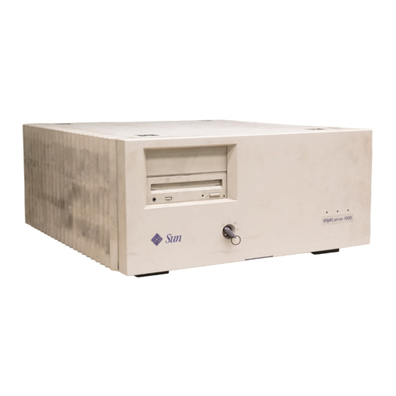
Page 17: Figure 1-1 Sparcserver 1000 System
Figure 1-1 SPARCserver 1000 System The internal components of the SPARCserver 1000 system are shown in Figure 1-1 and include the following: • Power supply • Fan tray • SCSI tray assembly with control board • System board Preparing for Installation... -
Page 18: Figure 1-2 Internal Components
System board Control board SCSI tray assembly Fan tray Power supply Figure 1-2 Internal Components SPARCserver 1000 System Installation Manual—June 1996... -
Page 19: Chassis Assembly
1.3 Chassis Assembly The chassis assembly, shown in Figure 1-3, consists of: • Chassis • Backplane The backplane is near the center of the system chassis. This allows for the insertion and removal of system components from both the front and rear of the system. -
Page 20: Power Supply
The connector routes AC power to the power supply and provides DC power for the fans and the fan fail signals. Backplane connectors (hidden) Key switch Fan tray connector LEDs Figure 1-4 Power Supply SPARCserver 1000 System Installation Manual—June 1996... -
Page 21: Fan Tray
1.3.2 Fan Tray The SPARCserver 1000 fan tray, shown in Figure 1-5, provides cooling for the power supply, system boards, and the SCSI tray assemblies. In addition, this module routes AC power from the rear of the chassis to the power supply. Each fan has a fail sensor to enable orderly system shutdown if a fan fails. -
Page 22: Scsi Tray Assembly
The control board mounts on top of the SCSI disk drive tray on the right and includes: • Central arbiter (CARB) • System clock • Service port • Reset switch SPARCserver 1000 System Installation Manual—June 1996... -
Page 23: System Board
SCSI disk drive tray Figure 1-6 SCSI Tray Assembly 1.3.4 System Board The SPARCserver 1000 system must have at least one system board installed in card cage slot 0. The system board (Figure 1-6) features: • One single-ended narrow SCSI-2 port •... -
Page 24: Options
• SuperSPARC modules • System board with 0 CPU and 0 Mbyte memory • System board with 2 CPU and 64 Mbyte memory • System board with 2 CPUs and 128 Mbyte memory 1-10 SPARCserver 1000 System Installation Manual—June 1996... -
Page 25: External Options
1.4.1 External Options External options usually require SBus interface cards. Each system board features three SBus slots for system expansion. Note – An Ethernet controller is incorporated directly on the system board so an SBus card is not needed for this function. A monitor is not necessary for normal server operation and many servers lack monitors. -
Page 26: Specifications
Power Supply Characteristics Parameter Value Input Voltage range 100-240 VAC Current 9.5A maximum at 100 VAC input with 650W load Frequency range 47-63 Hz Output +5 VDC 5 to 100A +1.2 VDC 0 to 40A 1-12 SPARCserver 1000 System Installation Manual—June 1996... -
Page 27: Environmental Requirements
Relatively dust-free (as in an office environment) 1.6 Site Preparation 1.6.1 Preparing Electrical Circuits Your SPARCserver 1000 system uses nominal input voltages of 115 VAC or 230 VAC. Sun™ products are designed to work with single-phase power systems having a grounded neutral conductor. -
Page 28: Preparing The Ethernet Network
Monitor used for diagnostics 1.6.2 Preparing the Ethernet Network The SPARCserver 1000 system follows the IEEE standard for 10Base-T Ethernet, which is also known as twisted-pair Ethernet. Under this standard two pairs of unshielded wires connect to each node (a workstation or file server). -
Page 29: Preparing The Tabletop Area
10BaseT Link Integrity Test function. 1.6.3 Preparing the Tabletop Area The SPARCserver 1000 system is designed to sit on a desk or table. Use the following guidelines to prepare a location for your server. - Page 30 1-16 SPARCserver 1000 System Installation Manual—June 1996...
-
Page 31: Setting Up The System
2.1 Unpacking the System Since you are reading this manual you have already opened the SPARCserver 1000 system shipping container and the box containing the manual set. Remove the key and power cord from their packing box and set them aside. These items are needed to power on the system. Follow graphic instructions on the shipping container to remove the server from the container. -
Page 32: Preparing The System For Cabling
This connector is in the lower left corner of the system rear. See Figure 2-2. 4. Plug the male connector on the power cord into a grounded wall outlet. The outlet must be a 110-240 VAC 15A circuit. SPARCserver 1000 System Installation Manual—June 1996... -
Page 33: Connecting The Network Cable To The Server
AC power switch AC connector Figure 2-2 AC Power Switch and Power Receptacle Caution – Do NOT turn on power to the unit yet. To do so could cause system damage to occur. 2.4 Connecting the Network Cable to the Server The main network interface is incorporated directly on the system board installed in slot 0 (top slot). -
Page 34: Connecting The Network Cable To The Transceiver
Screw the other Ethernet coaxial cable into the other round screw-on type connector on the transceiver. Figure 2-5 shows the elements used in the installation process. Determine if a terminator should be installed. Table 2-1 lists the cabling limitations for Ethernet. SPARCserver 1000 System Installation Manual—June 1996... -
Page 35: Figure 2-5 Connecting Twisted Pair Ethernet To N-Type Coaxial Cable
Example: transceivers are connected 15 meters apart (6 multiples of 2.5 meters), not 14.0 meters. Figure 2-6 shows an example of a typical network setup. The SPARCserver 1000 system can be any server shown in this figure. If termination is required, install a 50-ohm terminator in the unused transceiver N connector or the end of the coaxial cable. -
Page 36: Connecting An Ascii Terminal
Sun equipment and your hub, verify that your hub also has the link test function enabled. Refer to the Troubleshooting chapter in the SPARCserver 1000 System Service Manual and the manual provided with your hub for more information about the 10BaseT Link Integrity Test function. -
Page 37: Connecting External Scsi-2 Devices
2. Plug the terminal power cord to an AC wall outlet. 3. Configure the ASCII terminal as follows: • 9600 baud • 1 stop bit • 8 data bits • Parity off • Full duplex Refer to the instruction manual shipped with the terminal for specific configuration instructions. -
Page 38: Precautions For Jumpstart Automatic Installation
Note – If JumpStart automatic installation does begin, interrupt it by pressing L1-A (Stop-A), and then perform a manual installation when you are ready. If JumpStart completes the installation incorrectly, you would probably need to reinstall Solaris manually. SPARCserver 1000 System Installation Manual—June 1996... -
Page 39: Powering The System On And Off
Powering the System On and Off 3.1 Powering On the System Note – It is advisable to connect a TTY terminal to the system during installation (refer to Section 2.6, “Connecting an ASCII Terminal” to find instructions). Observe the yellow (middle) LED on the front panel. It should go off when boot completes. -
Page 40: Figure 3-1 Key Switch In The Standby Position
At the conclusion of testing, POST automatically attempts to reconfigure the system, omitting any parts of the system that have failed diagnostics. If there are no faults, or if POST completes a successful reconfiguration in response to detected faults, the system boots up. SPARCserver 1000 System Installation Manual—June 1996... -
Page 41: Figure 3-2 Key Switch In On Position
Standby Diagnostics Locked Figure 3-2 Key Switch in On Position Note – If faulty parts are detected and configured out of the working system, you and the system manager must decide whether to operate the system until replacement parts arrive, or to halt operation. Also, if a faulty component cannot be replaced in the field, the entire subassembly (like the system board) must be replaced. -
Page 42: Figure 3-3 Removing The Front Panel
Figure 3-3 Removing the Front Panel Reset switch (accessed through hole) LEDs Figure 3-4 Reset Switch (Behind the Front Panel) and System Status LEDs 5. Return the key to the key switch. SPARCserver 1000 System Installation Manual—June 1996... -
Page 43: Boot Messages
3.1.1 Boot Messages Use boot software messages to verify that all options are installed and recognized by the system. After POST completes self-test, a message like the following appears. It lists hardware components detected by the system. <<<< SPARCserver 1000XX POST V4.1 >>>> ... -
Page 44: Powering Off The System
6. Turn the AC power switch on the system rear off. For more information on system administration (such as methods for shut- down and backup) See the Preface, “When You Need Help with UNIX Commands” for references to documentation that describes these procedures. SPARCserver 1000 System Installation Manual—June 1996... -
Page 45: General Rules For System Configuration
General Rules for System Configuration This appendix lists recommended priorities and locations for: • System boards • SuperSPARC modules • SBus modules • SIMMs • Drive IDs • SCSI cables • Ethernet cables • Video cables A.1 Selecting Installation Locations Each component described in this appendix has a specific recommended location. -
Page 46: Supersparc Module
0. After all of the A connectors are filled, begin filling the B connectors, starting with the system board in slot 0 and working down. SuperSPARC module A SPARC connectors SuperSPARC module B Figure A-1 Locations of SuperSPARC modules SPARCserver 1000 System Installation Manual—June 1996... -
Page 47: Sbus Cards
The example in Table A-1 shows how to distribute four SuperSPARC modules on three system boards. Table A-1 Example of Connector and Slot Priorities System Board Slot 0 System Board Slot 1 System Board Slot 2 Connector A Full Full Full Connector B Full... -
Page 48: Simms
1 FSBE/S A.1.4 SIMMs The SPARCserver 1000 system has three SIMM options. Two types of DRAM, high-density and low-density, are available as well as nonvolatile NVSIMM. The 8 Mbyte (low-density) SIMM uses 1 Mbit by 4 bit DRAMs. Two vendors are used, so a slight variation exists in physical appearance between the two products. -
Page 49: Nvsimm
SIMM — Vendor 1 Capacity Type CBS4 CBS2 8 Mbyte DRAM 501-1817 32 Mbyte DRAM 501-2196 SIMM — Vendor 2 Capacity Type 8 Mbyte DRAM 501-1817 CBS - 22P CBS - 11P 32 Mbyte DRAM 501-2196 NVSIMM Capacity Type 1Mbyte NVSIMM 501-2197 Figure A-3... - Page 50 SIMM Locations on the System Board A.1.4.1 NVSIMM Before installing NVSIMMs you must first activate the battery to insure data retention. To activate the battery: 1. Locate the jumper on the right side of the NVSIMM. See Figure A-5. SPARCserver 1000 System Installation Manual—June 1996...
-
Page 51: Selecting Drive Id Numbers In The Scsi Tray
SCSI tray right side, behind a metal faceplate. The device IDs for these devices are 0, 1, 2, and 3. See Figure A-6. Note – Refer to the SPARCserver 1000 System Service Manual for specific information about setting device addresses on SCSI-2 devices. -
Page 52: Table A-3 Id Numbering In A Scsi Tray
Table A-3 lists the correct ID numbers for the six drives in the SCSI tray. Table A-3 ID Numbering in a SCSI Tray Device SunCD Tape drive Disk drive Disk drive Disk drive Disk drive SPARCserver 1000 System Installation Manual—June 1996... -
Page 53: Connecting Cables
0. Refer to Chapter 2 of this manual and to the instructions that come with your Ethernet transceivers for additional information. The SPARCserver 1000 system supports twisted-pair Ethernet installations. A.3.3 Video Cables Only one CGSIX interface is allowed per system. It must be installed in SBus slot 1 of system board 0. - Page 54 A-10 SPARCserver 1000 System Installation Manual—June 1996...
-
Page 55: Glossary
Glossary Air Restrictor Board A blank board with a special air deflector fin to simulate the airflow pattern of an actual board. If air restrictor boards are not installed in blank slots, a condition called a “thermal short” is created. Thermal shorts severely reduce the cooling capability of the system, which can lead to equipment damage. - Page 56 The term board refers to printed circuit boards larger than a certain size (for example, larger than 3x5-inch SBus cards and SPARC modules). There are two types of boards in the SPARCserver 1000 system: system boards (maximum of four) and control board (one only). See also Card and Module.
- Page 57 The BootBus is located on the system board. This bus connects the OpenBoot EPROM set on system board to the SPARC module(s). See also Bus. There are six basic types of busses in the SPARCserver 1000 system: • XDBus—the card cage backplane bus.
- Page 58 By convention, boards are installed in a card cage (not a board cage). The SPARCserver 1000 system card cage is accessed from the rear of the enclosure that contains up to four system or other boards. The card cage provides card guides to guide the board into the backplane.
- Page 59 Key Switch The key switch on the system front panel has four positions: Standby, On, Diagnostics, and Locked (reset switch is disabled, L1-A is disabled). LED Indicators System Front Panel For an explanation of this display, refer to Table 3-1, “Front Panel LED System Status.”...
- Page 60 Found only on the SuperSPARC module. To compare bus types, see Bus. Processor See SuperSPARC Module. Replaceable Unit Replaceable units are server subassemblies which can be replaced at the customer site by trained, qualified service personnel. Glossary-6 SPARCserver 1000 System Installation Manual—June 1996...
- Page 61 This 3x5-inch card contains one SuperSPARC processor, cache memory, and a cache controller. Note that main memory (SIMM groups) reside elsewhere on the system board. A system board can have two SuperSPARC modules. A SPARCserver 1000 system can have up to four such boards equaling eight modules. Status Registers Three status registers reside on the system board.
- Page 62 The XBus is a high-speed bus located on the SuperSPARC module. It connects the Bus Watchers (BWs), MXCC, IOC and SBΙ. See also Bus. XDBus This is the main card cage backplane bus. Glossary-8 SPARCserver 1000 System Installation Manual—June 1996...
- Page 63 Index ethernet length AC power routing preparation for Glossary-4 switch card cage Glossary-1 air restrictor board chassis ASCII terminal 1-12 clearance requirements configuration configuring, ASCII terminal connection connecting ASCII terminal ethernet cables Glossary-1 network cable backplane to server assembly to transceiver features power cord battery, NVSIMM...
- Page 64 Glossary-4 filler panel 1-15 network transceiver groups, SIMM Glossary-6 NVSIMM battery activation halting the system options 1-11 external installation 1-11 internal preparation for 1-10 list SBus card 1-11 SBus cards SIMM 1-11 SIMMs Index-2 SPARCserver 1000 System Installation Manual—June 1996...
- Page 65 1-11 SuperSPARC modules external ID numbers tray contents selecting POST SBus card location program SCSI ID numbers reconfiguration of system SIMM locations power cord, location SuperSPARC module location serial port A off the system 1-13 connection to output rating power supply shipping container, opening assembly SIMM...
- Page 66 Glossary-8 description ethernet port, location features slot positions task map transceiver cable, example of 1-15 network tty terminal removal 1-14 twisted-pair cables unpacking the system video cables, connecting Glossary-8 XBus Glossary-8 XDBus Index-4 SPARCserver 1000 System Installation Manual—June 1996...
- Page 67 Revision History Revision Dash Date Comments 801-2893-13 June 1996 2nd Revision to FCS 801-2893-11 August 1993 1st Revision to FCS 801-2893-10 May 1993 First Customer Ship (FCS)
- Page 68 SPARCserver 1000 System Installation Manual—June 1996...
- Page 69 The information I needed was easy to find. Strongly Strongly Agree Agree Disagree Disagree Applicable Comments The manual was useful to me. Strongly Strongly Agree Agree Disagree Disagree Applicable Comments Do you have additional comments about the SPARCserver 1000 System Installation Manual? Name: Title: Company: Address:...
- Page 70 IF MAILED IN THE UNITED STATES BUSINESS REPLY MAIL FIRST CLASS MAIL PERMIT NO. 1 MOUNTAIN VIEW, CA POSTAGE WILL BE PAID BY ADDRESSEE SUN MICROSYSTEMS, INC. Attn: Manager, Hardware Publications MS MTV15-42 2550 Garcia Avenue Mt. View, CA 94043...
Need help?
Do you have a question about the SPARCserver 1000 System and is the answer not in the manual?
Questions and answers