Datamax M-Class Mark II Operator's Manual
Datamax m-class mark ii: user guide
Hide thumbs
Also See for M-Class Mark II:
- Maintenance manual (94 pages) ,
- Manual (10 pages) ,
- Quick start manual (8 pages)
Table of Contents
Advertisement
Quick Links
Advertisement
Table of Contents
Troubleshooting

Subscribe to Our Youtube Channel
Related Manuals for Datamax M-Class Mark II


Summary of Contents for Datamax M-Class Mark II
- Page 1 Operator’s Manual...
-
Page 3: Limitation Of Liability
Datamax-O’Neil hereunder by the purchaser for a defective product. In no event shall Datamax-O’Neil be liable to the purchaser for any damages resulting from or related to any failure or delay of Datamax-O’Neil in the delivery or installation of the computer hardware, supplies or software or in the performance of any services. -
Page 4: Important Safety Instructions
• Do not use your printer near water, or spill liquid into it. • Be certain that your power source matches a listed voltage rating for the printer (if unsure, check with your dealer or local utility company). • Do not place the power cord where it can be stepped on; and, if the power cord becomes damaged, immediately replace it. -
Page 5: Table Of Contents
Getting Started Introduction ... 1 Unpacking ... 1 Printer Setup Printer Connections ... 3 Loading Media ... 6 Media Sensor Adjustment ... 8 Loading Ribbon ... 9 Printer Operation Front Panel (Non-Display Models) ... 13 Front Panel (Display-Equipped Models) ... 15 Windows Driver... - Page 6 Printhead Burn Line Adjustment ... 50 Printhead Pressure Adjustment ... 51 Printhead Replacement ... 52 Darkness Adjustment... 53 Resetting the Printer... 54 Downloading Firmware and Fonts ... 55 5.10 File Handling Messages (Display-Equipped Models) ... 56 Troubleshooting Problem Resolution... 59 Fault and Warning Messages (Display-Equipped Models) ...
-
Page 7: Getting Started
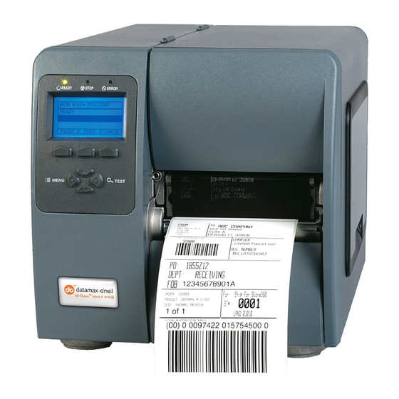
Congratulations on your M-Class Mark II printer purchase. The M-Class Mark II printer family, hereafter referred to as ‘the printer’, blends the rugged durability of die-cast construction with state-of-the-art electronics and user-friendly features to redefine the standard in industrial thermal printers. - Page 8 Chapter 1 – Getting Started...
-
Page 9: Printer Setup
2. Ensure that the Power Switch on the Printer is in the ‘Off’ position. 3. Connect the AC Power Cord to the receptacle on the back of the Printer, and then plug the AC Power Cord into a properly grounded outlet. (The power supply automatically detects and then adjusts to the applied line voltage;... -
Page 10: Interface Connection
Interface Connection The printer can be connected to the host via the parallel, USB, serial, or optional network interface. The printer will automatically connect to the first port that delivers valid data. Once established, the printer’s power must be cycled ‘Off’ and ‘On’ to change an interface connection. - Page 11 SDIO Connections - When installing an SDIO Card, turn OFF the printer then slide the card into the slot. Module “F” will be recognized by the printer. When removing a card, turn OFF the printer then press inward on the card to release it.
-
Page 12: Loading Media
2. Press in on the Printhead Latch and raise the Printhead Assembly. 3. Slide the Roll Media onto the Media Hub or Media Hanger. If the printer is equipped with a Media Hanger, raise the Media Hanger Guide. The Media Hanger Guide should be pushed inward so that it is just touching the Roll Media. - Page 13 5. Close the Printhead Assembly and press down until it locks into place. 6. Close the cover and press the proper tracking. If the printer does not correctly sense the top of each label, it may be necessary to calibrate the printer (see Section 3.5 Media Calibration). ...
-
Page 14: Media Sensor Adjustment
The Media Sensor needs to be positioned so that the printer can detect the presence of media and the top-of-form (except for continuous stock, where the TOF is set through the front panel. To adjust: 1. With media loaded, as described in Section 2.2, grasp the Slide Tab and move the Sensor Eye Mark into position over media according to the table below. -
Page 15: Loading Ribbon
Ribbon is required with thermal transfer media. It is recommended that the width of the ribbon be slightly wider than the media being used. The printer can use either ribbons with the ‘coating side in’ or ribbons with the ‘coating side out’. To load: Using a ribbon that is slightly wider than your media (and liner, if any) will help protect against •... - Page 16 Ribbon Routing Diagrams (CSI) ‘Coating Side In’ Ribbon Routing (CSO) ‘Coating Side Out’ Ribbon Routing Chapter 2 - Printer Setup...
- Page 17 3. Route the ribbon under the Ribbon Idler and then out the front of the printer approximately 12 inches. 4. Close the Printhead Assembly and press down until it locks into place. Chapter 2 - Printer Setup Ribbon Roll ...
- Page 18 5. Route the ribbon up and then around to the Ribbon Take-Up Hub, winding it several times in a clockwise direction to secure it in place. 6. Close the cover and press the Feed button several times to position the ribbon and ensure proper tracking. Chapter 2 - Printer Setup Ribbon Take-up Hub...
-
Page 19: Printer Operation
Indicates a top of form or mechanical error has occurred Solid On: Indicates the printer is on and ready for printing Flashing: Indicates the printer is receiving data from the host Lights will be on during power-up initialization. -
Page 20: Ready Mode Functions
Press and Hold Pause Empty Calibration Delayed Power-up Functions Turn on the printer, when the three lights turn on press and hold the button sequence. Continue to hold the button(s) until the three lights turn off. Function Hold Pause & Feed &... -
Page 21: Icons And Indicators
Main Display Area and the keyboard functions to change as operational events require. Icons & Indicators The icons are graphics that appear in the ‘Printer Status Line’ area of the display. Three LED indicators are located above the display. Both provide real-time operational information as defined... -
Page 22: Windows Driver
The Windows driver is located on the Accessories CD-Rom included with your printer. For the latest version please visit our web site at www.datamax-oneil.com. Installing the Windows Driver: Place the Accessories CD-Rom included with your printer into your computers CD-Rom drive. -
Page 23: Important Notes
Important Notes: The Windows driver functions the same as any other Windows printer. A built in help file is available for complete information on all settings; however, there are some important settings that should be observed for trouble free printing. -
Page 24: Printer Configuration Utility
DMXConfig (located on the Accessories CD-ROM) is a Windows based configuration utility that allows you to make changes to the existing printer setup via a direct connection to the host computers serial and parallel connection. DMXConfig Features: Allows Real-Time Control/Query of Printer Configuration ... -
Page 25: Quick Calibration
Calibrate the printer as follows: 1. Ensure that the printer is ON and in an idle state (i.e., not off-line) with media loaded, the media sensor adjusted, and the sensor type selected. 2. Press and hold the FEED Key until one label has been output then release the key and wait for the printer to process the data. -
Page 26: Standard Calibration
(see Appendix C). On display-equipped printers the Standard Calibration routine can also be initiated via the printer’s menu, see Section 4.5. Once you have installed the DMXConfig utility and the printer is properly loaded with media: 1. - Page 27 “OK”. 9. The Calibration Wizard will now respond with ‘Passed Calibration’, click “OK.” Re- install the media in the printer. Close the printhead and press the Feed button to test the calibration. Each press of the Feed button labels should feed one label.
-
Page 28: User Defined Label (Display-Equipped Models)
USB QWERTY keyboard). The template is a stored label format, where fields delimited by an ampersand (&) become variable. The printer will prompt you to enter the variable field data. For example, the stored label format could contain the data 19131423443&ENTER NAME&... -
Page 29: Menu System
The Test Menu accesses a menu of test, user-defined, and previous label printing functions. (1) Entering the Menu System takes the printer OFF-LINE and stops the processing of new data. (2) Prompts may appear before menu access is granted and before changes are enacted; see Security for details. -
Page 30: The User Menu
Changes prompt. (2) Labeling software may, in some cases, override the printer menu settings; see Advanced Menu / Communications / Host Settings to avoid potential conflicts. (3) To return to the User Menu, re-select it or restore the factory defaults. -
Page 31: Media Settings
Changes to these print settings can be made via the Menu System or through host commands. When printing, use full width media to capture the entire format; otherwise, adjust the printer and set the Label Width. (1) Press the CANCEL KEY to stop printing. - Page 32 04.00 Is the default setting. MAXIMUM LABEL Sets the distance (0 - 99.99 inches) that the printer will feed media to find TOF LENGTH (when the Sensor Type is set to GAP or REFLECTIVE) before a TOF Fault is declared, where: 16.00...
- Page 33 SENSOR Selects the media sensor calibration method, where: CALIBRATION PERFORM Sets the values via internal printer calculations, as described in the STANDARD CALIBRATION CALIBRATION procedure. ADVANCED ENTRY Sets the values via manual entry (typically for hard to calibrate label stocks), as...
-
Page 34: Print Control
Print Control The Print Control menu contains printing throughput, offset and custom setup functions: Heat Print Speed Feed Speed Reverse Speed * Slew Speed * Row Offset Column Offset Present Distance TOF Precedence ... - Page 35 AUTO Is the default setting (Auto Mode). In Auto Mode, the printer automatically 0.00 in. configures this distance according to the positioning requirements of the attached device (i.e., tear bar, cutter, peel &...
-
Page 36: Printer Options
Printer Options The Printer Options menu contains file-handling, module, and optional equipment settings: Modules Present Sensor Cutter RFID GPIO Port Items denoted with an asterisk (*) are only accessible through the Advanced Menu; also, certain selections will appear only when equipped with that option. - Page 37 FORMAT Selects from a list of modules available for formatting by the printer; see Section MODULE * 5.10, File Handling Messages. Choosing FORMAT MODULE will erase existing data in the selected module DELETE FILE * Selects from the list of available files for deleting; see Section 5.10, File Handling Messages.
- Page 38 Zero to nine are the number of retries; and, Is the default setting. PERFORM Allows the printer to establish the tag to transducer distance setting and nominal CALIBRATION * RFID power requirements. Initiates the process. The CALIBRATING RFID message will appear as the printer feeds media to begin scanning for the RFID tag location.
- Page 39 SET DEFAULTS * Depending upon the RFID MODULE, selecting YES will return these settings: If MODE = HF, then: RFID POSITION = 1.10 HF SETTINGS:TAG TYPE = ISO 15693 RETRY ATTEMPTS = 3 -------------------------------------------------------------------------------------------- ---- If MODE = UHF, then: RFID POSITION = 1.10 UHF SETTINGS:TAG TYPE = GEN 2;...
-
Page 40: System Settings
Returns the printer to a previously saved configuration. CURRENT * SAVE SETTING Creates a file based on the current printer configuration, as described here. DELETE FILE * Removes a selected configuration file from memory. (An active file cannot be deleted.) - Page 41 Is the Default Setting (DRAM module). Flash module. The available modules may vary depending upon printer model and options. SCALEABLE FONT Configures the number of 1KB blocks (100 - 5120) allocated for the scaleable font CACHE engine, where: 0511 KBytes Is the Default Setting.
- Page 42 Displays the hardware and software levels of the printer, where: LEVEL PRINTER KEY Identifies the unique key number of the printer, in the form: vvvv-cwxx-yyyyyy- zzz, where: - Represents the printer model number. vvvv - Represents the hardware/software feature level, where: cwxx - Represents the printer class.
- Page 43 DISABLED Labels are printed without pausing. (Default Setting) PEEL MODE Allows the printer to wait until the Start of Print signal is received (via the optional GPIO Port) to feed a label, where: ENABLED Inhibits the feed function until the Start of Print signal is received.
- Page 44 Uses millimeters and centimeters. INPUT MODE Defines the type of processing that will occur when data is received, where: Datamax-O’Neil programming language processing will be used. (Default Setting) LINE Line Mode processing will be used, where data terminated by a carriage return will be extracted and inserted for template printing.
- Page 45 ENABLED or SOP to allow fastest throughput. BACKUP DELAY Instructs the printer to retract a presented label after a specified time elapses (0 – (1/50s) 255, in one-fiftieth of a second increments), where: Retraction occurs when the next label is received and processed. (Default Setting)
- Page 46 RETRY COUNT Sets the number of reprint attempts, where: (0 – 3) Is the last label in the count to be voided before the printer will stop and display a fault message. (The default setting is one.) BACKFEED ON Determines the printer's action after a fault is cleared, where:...
- Page 47 One stop or two stop bits are selectable; and, is the Default Setting. PARALLEL PORT A Controls the communication setting for the parallel port, where: PORT Determines if data is returned from the printer, where: DIRECTION UNI- No data is returned; communication is one-way. DIRECTIONAL Data is returned in compliance with IEEE 1284 back-channel operation.
- Page 48 Automatic (advertises the DUPLEX CAPABILITY setting); or, • All Capabilities (advertises all capabilities) • NETWORK Prints or displays a report which lists the printer’s network settings. REPORT SET FACTORY Resets NIC Adapter parameters to the factory defaults values. DEFAULTS Chapter 4 – Menu System A server assigned IP address takes precedence over any static IP address stored in the interface.
- Page 49 Each DPL command (SOH, STX, CR, and count-by) may be selected by entering the CODES desired Hex code. FEEDBACK Allows the printer to return a Hex 1E (RS) after each label successfully prints, and a CHARACTERS Hex 1F (US) after each label batch successfully prints, where: ENABLED Sends feedback characters to the host.
- Page 50 RFID information is reported in hexadecimal format. RFID ASCII RFID information is reported in an ASCII format. PROCESS SOH Determines the way the printer responds to an Immediate Command (e.g., Get (DATA) Status, Module Storage, etc.), where: ENABLED Operations are interrupted upon receipt to process the command.
- Page 51 Saves the incoming data to Module H (USB thumbdrive) if present; otherwise, the file is stored on Module G. The file name, in the form [dmx_xxx_yyy.dpl], where the count is automatically incremented for every capture and a unique printer time stamp (xxx), is assigned.
-
Page 52: Mcl Options
SENSOR Displays the values (0 – 255) from the printer sensors, where: READINGS THR = Printhead thermistor sensor; TRAN = Gap media sensor (REFL when set to reflective); RIBM = Ribbon sensor; 24V = 24 volt power supply sensor; PS = Present sensor;... -
Page 53: Maintenance And Adjustments
Isopropyl alcohol is a flammable solvent; always take the proper precautions when using this substance. Proper cleaning is critical. To maintain peak performance of the printer, Datamax-O’Neil offers a complete line of cleaning products including pens, cards, films and swabs. Visit our website at http://www.datamax-oneil.com to learn more. -
Page 54: Cleaning The Printhead
5. Replace the ribbon and media. Lower the Printhead Assembly back to the locked position. 6. Close the cover. Plug in and turn ‘On’ the printer. Feed several labels to normalize tracking. Chapter 5 – Maintenance and Adjustments... -
Page 55: Automated Printhead Cleaning
Automated Printhead Cleaning 1. Remove media and ribbon. 2. Place a Datamax-O’Neil Cleaning Card, part number 70-2013-01 under the printhead. Lower and lock the printhead. Ensure that the Media Width Adjustment is not engaged. 3. Press and hold the TEST Key for approximately four seconds. -
Page 56: Printhead Burn Line Adjustment
In extreme cases, however, if media of a different thickness or rigidity is used (for example, heavy tag stock) the print quality can change. If you have questions, contact a qualified technician or Datamax-O’Neil Technical Support before proceeding. To adjust the Burn Line: 1. -
Page 57: Printhead Pressure Adjustment
To accommodate a variety of media types, printhead pressure is adjustable. This pressure is factory set to work with most media types, so this adjustment should only be performed after attempting to improve print quality through the use of the (1) heat and/or (2) print speed. When adjusting, use only the minimum pressure necessary for better imaging. -
Page 58: Printhead Replacement
If you have questions, contact a qualified technician or Datamax-O’Neil Technical Support before proceeding. 1. Touch a bare metal part of the printer’s frame to discharge any static electricity that may be present on your body. 2. Turn ‘Off’ and unplug the printer. Open the cover; if ribbon is installed, remove it. -
Page 59: Darkness Adjustment
Display-equipped printers: Use the printer’s menu to adjust Darkness; see Section 4.5, Print Control / Custom Adjustments. Large increases in the ‘Darkness Adjustment’ can shorten printhead life. If you need to ... -
Page 60: Resetting The Printer
Soft Reset - To reset the printer and clear any temporary host settings: 1. With the printer ‘On’, press and hold the four seconds. Level One Reset - To return the printer to the factory default settings or, if saved, to restore the Factory Setting File: 1. Turn ‘Off’ the printer. -
Page 61: Downloading Firmware And Fonts
When program updates and/or new features are added, they can be downloaded to the printer as follows: 1. Identify the new version for your model of printer from the Datamax-O’Neil Web site at www.datamax-oneil.com and download it onto your computer’s hard drive or a floppy disk. -
Page 62: File Handling Messages (Display-Equipped Models)
Copying TrueType Fonts (Display-equipped printers with SDIO/USB Host) To copy TrueType fonts (.TTF) to an external module for use by the printer: 1. Use Windows Explorer to download the font to the module. 2. Add a 2 digit DPL font ID to the file name (50-99, 9A-9Z, 9a-9z) then change the file extension to .dtf (for example, arial50.dtf);... - Page 63 Displayed Description Message No associated files can NO FILES be found to perform AVAILABLE the requested action. The file type NOT SUPPORTED requested is not supported. The file requested will PROTECTED, be copied to a COPY FILE? protected module. The module is UNFORMATTED unformatted.
- Page 64 Chapter 5 – Maintenance and Adjustments...
-
Page 65: Troubleshooting
Chapter 6 – Troubleshooting Try this solution… Observe the Ready Indicator as the format is sent to the printer. If it does not flash, check the parallel cable type. Also, check the protocol and port settings between the printer and host. - Page 66 Adjustments / Column Offset; see Section 4.5. • Verify that the AC power cord connection has been made at both the outlet and the printer; also, ensure the power switch is ‘On’. • Verify that the AC outlet is functioning, or try moving the printer to another AC circuit.
- Page 67 Print any Internal Test Label (non-display printers, see Section 3.1.2; display-equipped printers, see Section 4.4.) If an image printed, then check the protocol and port settings for both the printer and host. These must match. • The heat setting may be too low. Make an adjustment in the software program or through the Front Panel.
- Page 68 If experiencing this problem… Poor print quality: Skips labels when printing: Unable to print rotated text: Chapter 6 – Troubleshooting Try this solution… • The printhead may need cleaning; see Section 5.2. • Adjust the Heat and Print Speed settings through the Front Panel or by host commands (non-display printers, see Section 3.4;...
-
Page 69: Fault And Warning Messages (Display-Equipped Models)
Fault Messages receive the highest display priority. If more than one fault is detected, the display will toggle between messages. To return to normal operation after the printer enters a fault condition, the fault must be corrected and then the FEED Key must be pressed to clear the condition. Displayed Message ... - Page 70 (2) if necessary, calibrate the printer; see Section 3.5. Try cycling the printer power ‘Off’ and ‘On’. If the fault does not clear, call for service. Try cycling the printer power ‘Off’ and ‘On’.
- Page 71 4) Ensure that the media and paper combination is not slipping (usually caused by an incorrect match). Turn ‘Off’ the printer until cool to prevent permanent damage due to an excessive printhead temperature. Possible Solution(s)
- Page 72 Displayed Message The printer could not find the TOF mark within the maximum label length setting or it found a TOF in an unexpected place. When the printer is set for reflective media, this fault is given for an out of stock condition.
-
Page 73: Warning Messages
The printer was unable to save settings in permanent memory. The printer was unable to find a DHCP server. A high printhead temperature has been detected. Chapter 6 – Troubleshooting... -
Page 74: Hex Dump Mode
Section 4.5. Exit the menu and save the changes. Now, ‘HEX DUMP MODE’ will be indicated by the display and all data sent to the printer will now be output in hexadecimal code, along with the printable ASCII equivalents, as shown below. To exit Hex Dump Mode, re-enter the Diagnostics Menu and disable the Hex Dump Mode, exit the menu, then save the changes. - Page 75 Mechanical Width Depth Height Weight Operating Temperature Humidity AC Input Voltage Printing Print Method Print Speed Resolution Tear Bar DRAM Memory FLASH Memory Appendix A – Specifications 9.8” (24.9 cm) 18.06” (45.9 cm) 10.3” (26.2 cm) 27.0 lbs. (12.2 kg) 40°...
-
Page 76: Embedded Fonts And Barcodes
Stop Bits Data Bits Embedded Fonts and Barcodes The printer is equipped with the most popular industry fonts and bar codes; see the Class Series 2 Programmer’s Manual for full listings and detailed information. Non-display printers 9 Bit Map Fonts; rotated 0, 90, 180, 270 ... -
Page 77: Approved Media
Approved Media To achieve optimum print quality and maximum printhead life, Datamax-O’Neil specifies the use of Datamax-O’Neil brand media and ribbons. These supplies are specially formulated for use in our printers; use of non-Datamax-O’Neil supplies may affect the print quality, performance, and life of the printer or its components. -
Page 78: Appendix A - Specifications
Appendix A – Specifications... -
Page 79: Gpio Port Configuration
The connection to the GPIO signals can be accessed via the Option Port connector (an 8-pin Molex Microfit 3, P/N 44300-800) on the front of the printer, or via the J6 connector (an AMP, P/N 640456-8) on the Main PCB. The pin-outs for the respective connectors (as viewed when facing... - Page 80 GPIO Device to “APPLICATOR”). Use the Configuration Set command (<STX>Kc), or program the selections on non-display models via the “Printer Setup Menu List” or on display-equipped models via the “Menu System.” Pin 3 should be pulled to +5VDC. In addition, connections...
- Page 81 In ‘Printer Setup’ mode, the buttons control the setting of the printer’s operational items such as media settings, communications, and options as detailed below. Before entering Setup Mode, exit Peel Mode (or, if equipped, disable the optional Present Sensor) as unpredictable results can otherwise occur.
-
Page 82: Printer Setup Menu List
Printer Setup Menu List The Printer Setup Menu List label, shown below, contains the printer’s current values for each menu item that can be modified via the front panel. The Menu Item Numbers correspond to the item’s position in the Menu List for selection when pressing the button during the Printer Setup Procedure. -
Page 83: Menu Items And Values
Menu Items and Values The table below details the Printer Setup Menu List items with a brief description of the item’s function, and the possible values. A “*” denotes the default setting. 1) MEDIA TYPE Sets printing for direct thermal (no ribbon) or thermal transfer (ribbon) media. - Page 84 19) INPUT MODE Selects between the standard or template interpretation of incoming data. Possible Values: * DPL (printer constructs the label using the standard DPL commands) LINE (printer constructs the label using a preloaded template form) Appendix C – Paper Menu Setup...
- Page 85 Heat Setting on most label software programs. Possible Values: Range: 0 – 30; default = *10 23) GPIO Sets the printer’s option port to function for GPIO applications, (see Appendix B for more information). Possible Values: YES or NO; default = *NO...
-
Page 86: Step By Step Modification Of The Printer Setup
Step by Step Modification of the Printer Setup The following is an example of Printer Setup modification. Although this example will detail how to modify the serial Baud Rate, the same method can be used to change any of the printer’s menu item settings. - Page 87 6. To confirm that your changes have been made press the simultaneously, this will print the Database Configuration Label. The label should show the new Baud Rate value of 19200. Label 1 WED NOVEMBER 10, 2003 21:41:31 323 VER: M4206 - 05.08 11/07/03 BOOT 83-2383-05E COUNTER INFORMATION CODE 83-2385-05H...
-
Page 88: Label Alignment = Yes
0.01” can result in noticeable print variations on the labels between the media sensor and the printhead. The measured value must be sent to the printer via the host computer or entered using the Printer Setup Mode. Then, in Normal Mode, press and hold the (about 4 seconds). -
Page 89: Label Alignment = Auto
The printer will feed labels to calculate the label length. Following the calculation, the printer will save the measurement and align to the top of form position. Auto Alignment can result in wasted labels during the measurement process (the longer the label length the greater the waste). -
Page 90: Label Alignment Troubleshooting
FEED length measurement. Re-measure the Label Alignment Length. Use Printer Setup mode to enter the new length. Print a Database Configuration label to ensure the new length has been set. Set Label Alignment to AUTO, press and hold ... - Page 91 Problem Possible Cause Label Alignment is Label Alignment incorrect. Pressing Length is not correct. The default Label successively FEED Alignment Length is results in a label 1.00”, and will result in length longer than this behavior when any actual, one-inch. larger label length is used without setting the appropriate length...
- Page 92 In ‘Calibration’ mode, the buttons allow the printer to adjust to the media being used. Calibration can be performed either automatically or manually, as detailed below. Before calibrating, ensure that the Printhead Carrier Assembly is latched down, that the cover is closed, and that the media sensor has been set for the appropriate media type.
-
Page 93: Auto Media Sensor Calibration
ERROR Manual Media Sensor Calibration. If you wish to discard the changes and revert back to the previous calibration simply turn off the printer before Step 4. 4. Now save the changes and resume simultaneously and briefly. Wait until the Appendix C –... -
Page 94: Manual Media Sensor Calibration
(feeds a label), and the FEED current calibration. If you wish to discard the changes and revert back to the previous calibration simply turn off the printer before Step 7. 7. Now save the changes and resume simultaneously and briefly. Wait until the Appendix C –... - Page 95 Different languages and / or Datamax-O’Neil-provided translations can be downloaded to replace the standard (English) menu of the printer by changing the spreadsheet that defines the system dictionary. To change the language you will add a new language column (or modify the existing column) in the spreadsheet, click on the “Generate DPL file(s)”...
- Page 96 B. Click the “Enable Macro” box. The following screen appears: C. Click on Column J and enter the new language, or modify an existing one. Some tips on this process: Message Size – When entering new messages, reference the “MAX” column: this is the •...
- Page 97 An error has occurred if the printer displays the new language selection, but all messages remain in English. In this case, re-check your process or contact Datamax-O’Neil Technical Support (be ready to provide the Common.xls and DPL download files created). Other error...
- Page 98 To restore the factory generated EFIGS image, download the file *832296.01A to the printer. • This file is located on the Datamax-O’Neil FTP site. The letter at the end of the file name (e.g., A) specifies the revision. The latest revision will be available on the FTP site.
- Page 99 • The screen shot below is an example of Unicode defined languages, Chinese & Russian. Note the only additional information required is the “double” in row 1. Appendix D – Changing the Language...
Need help?
Do you have a question about the M-Class Mark II and is the answer not in the manual?
Questions and answers