Table of Contents
Advertisement
Quick Links
Advertisement
Table of Contents
Troubleshooting

Related Manuals for Datamax Mark II


Summary of Contents for Datamax Mark II
- Page 1 Operator’s Manual...
-
Page 3: Copyright Information
Copyright Information CG Triumvirate is a trademark of Agfa Corporation. CG Times based upon Times New Roman under license from the Monotype Corporation. Windows is a registered trademark of the Microsoft Corporation. All other brand and product names are trademarks, service marks, registered trademarks, or registered service marks of their respective companies. - Page 4 Agency Compliance and Approvals UL60950-1, First Edition, Information Technology Equipment CSA C22.2 No. 60950-1-03, First Edition Listed IEC 60950-1 :2001, First Edition The manufacturer declares under sole responsibility that this product conforms to the following standards or other normative documents: EMC: EN 55022 (2006) Class A EN 50024 (1998) Safety: This product complies with the requirements of IEC 60950-1:2001, First Edition...
-
Page 5: Table Of Contents
Introduction ......................1 Unpacking the Printer ................... 1 Introduction ......................3 Connecting the Printer ..................3 2.2.1 Power Connections ..................3 2.2.2 Interface Connections ................. 4 ... - Page 6 3.7.3 Standard Calibration ................. 21 Internal Labels....................23 3.8.1 Database Configuration Label ..............23 3.8.2 Test Label ....................23 3.8.3 Hex Dump Label..................24 Introduction ...................... 25 ...
- Page 7 B.4.1 Auto Media Sensor Calibration ..............51 B.4.2 Manual Media Sensor Calibration ..............52 Network Card Reset.................... 53 Network Card Setup ................... 53 Network Card Setup - Wireless (Infrastructure Mode) ..........54 ...
-
Page 9: G E T T I N G S T A R T E D
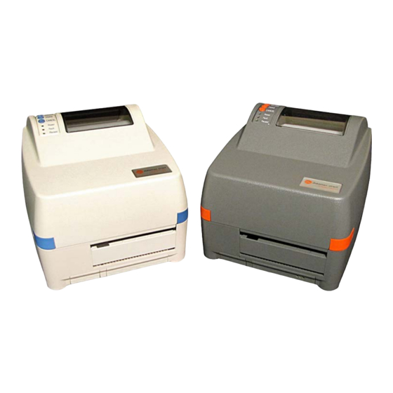
The E-Class Mark II printer (hereafter referred to as “the printer”) is user-friendly thermal printing device that blends quality and durability in an affordable package to meet all of your labeling needs. This manual provides the information necessary to operate and maintain the printer. - Page 10 Chapter 1 – Getting Started...
-
Page 11: P P S S
This section explains how to connect your printer, load media (including ribbon, if equipped for thermal transfer operation) and print a configuration label. 2.2.1 Power Connections The printer is powered by an external auto-ranging power supply, which connects between the printer and an electrical outlet. -
Page 12: Interface Connections
2.2.2 Interface Connections The printer can be connected to the host system via the parallel, serial and USB ports. Before connecting interface cables to the printer, ensure that the Power Switch is in the OFF (O) position. Parallel Port ... -
Page 13: Identifying The Media Sensor
The printer is available with a Stationary or an Adjustable Media Sensor. Press the Printhead Latch and then raise the Printhead Carrier Assembly to determine the type of sensor, and positioning requirement if any: The Stationary Media Sensor (shown below) is immovable; if the printer is equipped with this ... -
Page 14: Positioning The Adjustable Media Sensor
2.3.1 Positioning the Adjustable Media Sensor The Adjustable Media Sensor (AMS) allows the printer to accept a wider variety of media configurations. The table below defines general AMS positions for various media and Top of Form (TOF) types. AMS Positioning Media Type Sensor Location TOF Sensing Method... -
Page 15: Loading Media
c) Slide the Top AMS Window over the Reference Letter determined in Step b, above. d) Slide the Bottom AMS Window over the same Reference Letter. e) Load media; see Section 2.4. Top Slide Top AMS Window Bottom Slide ... - Page 16 Standoff Printhead Latch Printhead Carrier Assembly Media e) Route Media through the printer, as shown. Flange (against Roll Media) Media Guide (against Media) Media (Left-Justified) Slide the Roll Media completely leftward and then position the Flange against the roll. g) Slide the Media leftward and then position the Media Guide lightly against the side of the media.
-
Page 17: Peeling
2.4.1 Peeling Load media for peeling (if the printer is equipped with the option) as follows: When using the Peel Mechanism do not exceed a print speed of 4 IPS. a) Load media as described in Section 2.4. b) Press the Printhead Latch and raise the Printhead Carrier Assembly. c) Pull the Peel Lever forward. -
Page 18: Loading Ribbon
Ribbon, required when printing on thermal transfer media, is loaded as follows: If equipped with the thermal transfer option, the printer is factory set to use ribbon; see Section 3.4 to change this setting if using direct thermal media. a) If installed in the Ribbon Handler, remove the Ribbon Hubs. - Page 19 d) Place the Ribbon Hub with the Core into the Take-Up Position in the Ribbon Handler and place the Ribbon Hub with the Ribbon Roll into the Supply Position. Route the ribbon from the supply roll around the Printhead Carrier Assembly to the take-up roll, as shown below. ...
- Page 20 Chapter 2 – Printer Setup...
-
Page 21: P P R R I I N N T T E E R R O O P P E E R R A A T T I I O O N N
The Front Panel consists of three indicator lights and multi-function buttons, as detailed in the following sections. Three Indicator Lights provide a quick visual reference of printer operations and conditions, as defined below: (Normal power-up) Normal Mode Indicates the printer is on Power Indicates a top of form or mechanical Fault... -
Page 22: Multi-Function Buttons
Three buttons ( , and perform different functions depending upon the mode of the printer: Ready Mode Functions Control, calibration, and test functions can be performed when the printer is idle. Initiate the desired function by pressing the respective button (or button combination) as detailed below. Function Button(s) Description... -
Page 23: Printer Configuration Tools
The printer contains many user adjustable parameters. These parameters are configurable using a few methods. The table below lists the most popular ways of configuring the printer and the advantages of each. Choose the method that best addresses your application. Method Description Pros... -
Page 24: Printer Configuration Utility (Dmxconfig)
DMXConfig (located on the Accessories CD-ROM) is a Windows-based configuration utility that allows the user to make changes to the existing printer setup via a direct connection to the host computer’s serial, USB, or parallel ports. DMXConfig Features: Allows Real-Time Control/Query of Printer Configuration ... - Page 25 Once you have installed the DMXConfig utility: 1. Connect the host to the printer with a serial or parallel cable. 2. Turn ON the printer. 3. Launch the DMXConfig utility. 4. Query the printer by using the Query Printer toolbar button (top-left). This will connect to the printer and get the current printer settings.
-
Page 26: Windows Driver
The Windows driver is located on the Accessories CD-ROM included with your printer. For the latest version please visit our web site at http://www.datamax-oneil.com Installing the Windows Driver: Place the Accessories CD-ROM included with your printer into your computers CD-ROM drive. Once the CD-ROM starts select Install Windows Driver from the main menu and follow the instructions on the screen to install. -
Page 27: Important Notes
Important Notes: The Windows driver functions the same as any other Windows printer. While built-in help files provide information on all settings, there are some important setting parameters that should be observed for trouble free printing: Page Setup Tab: Stock Options Tab: Print Speed &... -
Page 28: Media Calibration
Calibration ensures correct media detection. 3.7.1 Quick Calibration Quick Calibration should be performed as part of the media loading routine to fine-tune the sensing parameters. This calibration is not necessary when using continuous stock. Media containing large gaps may require a change in the Paper Out Distance before proceeding; ... -
Page 29: Standard Calibration
3.7.3 Standard Calibration The Standard Calibration can be performed using the DMXConfig Utility (see Section 3.5), or via the front panel buttons (see Appendix B). Once you have installed the DMXConfig utility and the printer is properly loaded with media, proceed with calibration as follows: 1. - Page 30 7. The Calibration Wizard will now prompt you to Load Backing. Peel off a few labels and position the backing material in the media sensor. Close the printhead and click OK. 8. The Calibration Wizard will now prompt you to Remove Stock.
-
Page 31: Internal Labels
The following section details the resident information and test labels. 3.8.1 Database Configuration Label The Database Configuration Label provides information including the printer firmware version, memory allocations, enabled options, and label-counter data. Print a Database Configuration Label as follows: Load with media (4 inch wide) and ribbon (if printing with thermal transfer media), then press the Buttons simultaneously. -
Page 32: Hex Dump Label
3.8.3 Hex Dump Label The Hex Dump Label is a useful tool in the diagnosis of problems including communications handshaking and DPL syntax errors. To generate a Hex Dump Label the printer enters into Hex Dump Mode. In this mode, all data sent to the printer will be immediately output in hexadecimal code, along with the printable ASCII equivalents. -
Page 33: M A I N T E N A N C E A N D A D J U S T M E N T S
This section details the cleaning, adjusting, and troubleshooting tips for the printer. The following table outlines the recommended maintenance schedule for the various printer parts. Area Method Interval Turn OFF the printer before cleaning the printhead. Printhead Use solvent* applied with a cotton swab to clean After every roll of media. -
Page 34: Cleaning The Printhead
Never use a sharp, hard, or abrasive object on the printhead. If print quality declines (symptoms can include unreadable bar codes or streaks through text and graphics), the typical cause is debris buildup on the printhead which, left unattended, can lead to premature dot failure. Depending upon the supplies and printing parameters used, different cleaning methods are recommended. -
Page 35: Cleaning Card Procedure
Cleaning Card Procedure If printing with direct thermal media, thermal transfer media with wax/resin ribbon combinations, or if the Cotton Swab technique was not successful, clean the printhead as follows: a) Press the Printhead Latch and then raise the Printhead Carrier Assembly. Wait briefly for the Printhead to cool. -
Page 36: Media Width Adjustment
The Media Width Thumbwheel adjusts the printer to accept various widths of media. Adjust for narrow media by turning the Media Width Thumbwheel to the left (clockwise); conversely, adjust for wide media by turning the Thumbwheel to the right (counterclockwise). ... -
Page 37: Printhead Adjustment
The Printhead Adjustment Screw, located on top of the Printhead Carrier Assembly, is used to mechanically adjust print quality. Printhead placement is factory-set and should not need further adjustment; however, with the different types and thicknesses of media, readjustment may be necessary when print quality suffers. Printhead Adjustment should only be performed after attempting to improve print quality through the use of other print quality controls (see Section 3.5). -
Page 38: Printhead Replacement
If the Printhead becomes damaged, replace it as follows: Always follow proper Electro Static Discharge procedures when replacing the printhead. If equipped with a Ribbon Handler, it is not necessary to remove the assembly as an access hole ... -
Page 39: Downloading Firmware And Fonts
The operating programs and fonts for the printer are stored in Flash memory on the Main PCB. When program updates and/or new features are added, they can be downloaded to the printer as follows: 1. Identify the new version for your model of printer from the Datamax-O’Neil FTP site at ftp.datamax- oneil.com and download it onto your computer’s hard drive or a floppy disk. - Page 40 Chapter 4 – Maintenance Adjustments...
-
Page 41: T T R R O O U U B B L L E E S S H H O O O O T T I I N N G G
Occasionally, situations arise that require troubleshooting. Possible problem situations and potential solutions are listed below. Contact a qualified technician for problems that persist or problems not covered in this section. The following section lists the symptoms and the associated page numbers of the topics covered. While not every situation is addressed, you may find some tips helpful. - Page 42 Skips every other label (print quality is good, but every other label is skipped): The label is formatted too close to the top edge of the label: Leave white space equal to 8-dot rows (about .02 inch [.5mm]) at the top of the label. The media is not calibrated: Calibrate it (see Section 3.7).
-
Page 43: S P E C I F I C A T I O N S
Mechanical Width 8.77 inches (22.3 cm) Depth 10.0 inches (25.4 cm) Height 7.05 inches (17.9 cm) Weight 5.2 pounds (2.4 kg) 40 to 95 F (4 to 35 C) Operating Temperature AC Input Voltage Power Supply 105 VAC to 250 VAC / 50-60 Hz Printing Print Method Direct Thermal;... -
Page 44: Embedded Bar Codes
Media / Ribbon Media Types Roll-Fed, Die-Cut, Continuous, Fan-Fold Max. Media Width 4.3 inches (109mm) Min. Media Width 0.75 inches (19mm) E-4205e: 4.25 inches (108mm) Max. Print Width E-4304e: 4.12 inches (106mm) .375 – 100 inches (9.5 - 2540mm); min length of 1 .25 inches Print Length Range (31.8mm) with optional Cutter. -
Page 45: Approved Media
Approved Media To achieve optimum print quality and maximum printhead life, Datamax-O’Neil specifies the use of Datamax- O’Neil brand media and ribbons. These supplies are specially formulated for use in our printers; use of other supplies may affect the print quality, performance, and life of the printer or its components. For a current list of approved media and ribbons for use in direct thermal and thermal transfer applications, please contact a Media Representative at (407) 523-5650. - Page 46 Appendix A – Specifications...
-
Page 47: I I N N T T E E R R N N A A L L M M E E N N U U
Three buttons (PAUSE, FEED, and CANCEL) perform different functions based on the printer’s mode: Normal: Normal printer functions; see Section 3.3. Printer Setup: Allows changes to the operational settings; see Section B.2. Calibration: Allows media calibration for the correct sensing of the top of form; see Section B.4. In Setup Mode, the buttons control the settings of such items as media type, communications, and options as detailed below. - Page 48 To change Printer Setup, proceed as follows: (Press and hold during power-up until the Paused Light turns off) Printer Setup Mode F1 Prints the ‘Printer Setup Menu List’, see section B.2.1 Press and Feeds one label for “test” Release Press and hold to advance to the desired menu item by counting the number of Fault Light flashes F3 Prints the ‘Test Label’...
-
Page 49: Printer Setup Menu List
B.2.1 Printer Setup Menu List The Printer Setup Menu List label, shown below, contains the printer’s current values for each menu item that can be modified via the front panel (see Section B.2.2 for detailed item descriptions). The Menu Item Numbers correspond to the item’s position in the Menu List for selection when pressing the Button during the Printer Setup Procedure. -
Page 50: Menu Items And Values
B.2.2 Menu Items and Values The table below details the Printer Setup Menu List with a brief description of the item’s function and possible values, where an asterisk (*) denotes the default setting. 1) MEDIA TYPE 2) SENSOR TYPE 3) PRESENT SENSOR Sets printing for direct thermal Selects the sensor type used to Enables/Disables the optional... - Page 51 13) LABEL WIDTH 14) SCALABLE FONT 15) INTERNAL MODULE Sets the label width. Sets the number of memory Sets the number of memory blocks to allocate for scalable blocks to allocate for the internal Possible Values: fonts. RAM module. Range: 75 – 426; default = Possible Values: Possible Values: *426...
- Page 52 21) HEAT 22) IMAGING MODE Controls the “burn-time” of the printhead. This is This command instructs the printer whether to pre- the equivalent of Heat Setting on most label image the label format: software programs. Possible Values: Possible Values: Range: 0 – 30; default = *10 * Multiple label (The printer images multiple labels as memory permits, achieving the fastest throughput;...
-
Page 53: Step By Step Modification Of The Printer Setup
B.2.3 Step by Step Modification of the Printer Setup The following is an example of Printer Setup modification. Although this example will detail how to modify the serial Baud Rate, the same method can be used to change any of the printer’s menu item settings. ... -
Page 54: Label Alignment
The Label Alignment function is intended for use when the label length is less than the distance between the printhead and the media sensor or where label waste at power-up is a concern. Label Alignment (see table below) is not recommended for label lengths greater than 6.5 inches or for media containing 2 or more form lengths. -
Page 55: Label Alignment = Auto
B.3.2 Label Alignment = AUTO In this mode, the printer automatically calculates the ALIGN LENGTH thus eliminating the need to physically measure the label. This mode is usually preferred in applications that require frequent media changes to labels of different lengths. To perform an Auto Alignment, in Normal Mode press and hold the FEED Button (about 4 seconds). -
Page 56: Label Alignment Troubleshooting
B.3.4 Label Alignment Troubleshooting If you experience label alignment problems, the following table offers possible causes and solutions. Problem Possible Cause Solution Attempting to With the Present Set Label Alignment to AUTO, press and hold the FEED Button until perform Label Sensor enabled, Label media moves for the automatic length measurement. - Page 57 Problem Possible Cause Solution Tear Mode is Another present Disable the Present Sensor. selected but the position has been ~OR~ label stop position determined. Enabling (present position) is the Present Sensor Ensure the host computer is not providing a Present Distance ...
-
Page 58: Calibration Mode - Button Functions
– – – In Calibration Mode the buttons allow the printer to adjust to the media being used. Calibration can be performed either automatically or manually, as detailed below. Before calibrating, ensure that the Printhead Carrier Assembly is latched down, that the cover is ... -
Page 59: Auto Media Sensor Calibration
B.4.1 Auto Media Sensor Calibration Auto Media Sensor Calibration automatically establishes the optimum sensing values for the media you are using in the printer. Before calibrating, be sure the media sensor is set for the appropriate media type; also, ensure that the Printhead Carrier Assembly is latched down and the cover is closed. -
Page 60: Manual Media Sensor Calibration
B.4.2 Manual Media Sensor Calibration The Manual Media Sensor Calibration procedure should be used in cases where the printer continues to suffer from media sensing problems after performing or attempting to perform the Auto Media Sensor Calibration. Before calibrating, be sure the media sensor is set for the appropriate media type; also, ensure that the Printhead Carrier Assembly is latched down and the cover is closed. -
Page 61: Network Card Reset
It is recommended that the communication settings be reset to factory defaults to avoid any conflicts in configuration. To reset the printer’s communication settings: Turn ON the printer, and then when the three LEDs illuminate press and hold the Buttons until all three lights turn OFF. -
Page 62: Network Card Setup - Wireless (Infrastructure Mode)
After a successful setup is made via a wired connection, the Wireless connection (if equipped) can now be configured in Infrastructure Mode using a static or DHCP issued IP address. Wireless Active LED Link LED Transmit Receive LED 1. -
Page 63: Printer's Internal Web
Once the previous steps have been successfully completed you may now use the IP Address to: > Install a printer driver, and start printing from your Windows applications; see Section C.6. -or- > Browse to the internal web pages for advanced configuration; see Section C.4. ’... - Page 64 TCP/IP Configuration Page Static IP Settings IP Address These are the static address the printer will use when IP Discovery is set to disabled or a Subnet Mask valid IP could not be retrieved from a DHCP server. Default Gateway DHCP Settings Controls IP Address discovery, where: Enable IP Discovery...
- Page 65 WiFi Configuration Page WLAN Network Settings SSID Service Set Identifier that identifies the Module to connect to an AP. To make this connection, the Module and AP must have the same SSID. The SSID cannot contain spaces. Default setting is the MAC address of the wireless module. WLAN Network Type Specifies the type of network in which the Module will be used: Infrastructure = connects to WLAN using an AP.
- Page 66 WiFi Configuration Page (continued…) Advanced Settings Maximum Transmission Specifies the module’s maximum wireless transmission rate. Default is 2 Mbps. Rate Use Fixed Rate for Sets the 802.11 behavior for Adhoc Mode. Default is 0. Transmission WLAN IP Settings DHCP Displays the current DHCP mode status. DHCP Fallback This is the IP address to use with DHCP is enabled and a DHCP server cannot be found.
-
Page 67: Dmx Config Utility
DMXConfig (located on the Accessories CD-ROM) is a Windows based configuration utility that allows the user to make changes to the existing printer setup via a direct connection to the host computers serial and parallel connection. This is a vital tool for the use and configuration of wired and wireless printer setup. Be sure to use the DMXConfig utility located on the Accessories CD-ROM that is included with your printer. - Page 68 Wireless Configuration - Adhoc Mode: Note: The following example uses the DMXConfig software utility to configure the printer. 1. Connect the host to the printer with a serial or parallel cable. 2. Turn ON the printer. 3. Launch the DMXConfig utility. Query the printer by using the Query Printer toolbar button (top-left).
-
Page 69: Installing The Printer Driver
Install the Printer Driver as follows (screen shots below are samples taken using Windows 2000; other versions will be similar): Start the Make sure that Windows Local Printer is selected and Printer Wizard. then click The following Next>. screen should appear, and then click Next>. - Page 70 Insert the Browse to the Accessories CD- \DRIVERS\ ROM and click Seagull folder Browse. on the CD-ROM. Ensure the file “Datamax for 95, 98, ME, 2000, and xp.inf is selected” then click OK. Click OK. Choose your printer from the list and then click Next>.
-
Page 71: G L O S S A R Y
alphanumeric Consisting of alphabetic, numeric, punctuation and other symbols. backing material The silicon-coated paper carrier material to which labels with adhesive backing are affixed. Also referred to as “liner”. bar code A representation of alphanumeric information in a pattern of machine-readable marks. The basic categories are divided into one-dimensional (UPC, Code 39, Postnet, etc.) and two- dimensional barcodes (DataMatrix, MaxiCode, PDF417, etc.). - Page 72 font A set of alphanumeric characters that share a particular typeface. gap A space between die-cut or notched labels used to sense the top of form. IPS (inches per second) Imperial measurement of printer speeds. label A paper or synthetic printing material, typically with a pressure sensitive adhesive backing. label length The distance from the top of the label to the bottom of the label as it exits the printer.
Need help?
Do you have a question about the Mark II and is the answer not in the manual?
Questions and answers