Table of Contents
Advertisement
Quick Links
Advertisement
Table of Contents

Related Manuals for ECOTEST STORA-ABG RKS-01


Summary of Contents for ECOTEST STORA-ABG RKS-01
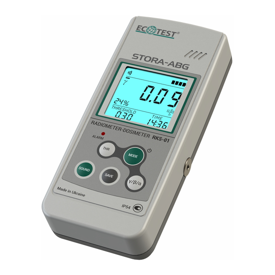
- Page 1 RKS-01 “STORA-ABG” RADIOMETER-DOSIMETER Operating Manual...
-
Page 3: Table Of Contents
ЗМІСТ 1 DESCRIPTION AND OPERATION ..................4 1.1 P ................4 URPOSE OF USE OF THE RADIOMETER 1.2 T ..................5 ECHNICAL SPECIFICATIONS 1.3 D ......................19 ELIVERY KIT 1.4 D ............... 24 ESIGN AND PRINCIPLE OF OPERATION 1.5 L ..................... 31 ABELING AND SEALING 1.6 P ........................ - Page 4 4 CERTIFICATE OF ACCEPTANCE ..................123 5 PACKING CERTIFICATE ....................124 6 WARRANTY........................125 7 REPAIR ..........................126 8 STORAGE ..........................128 9 SHIPPING ..........................129 10 DISPOSAL.......................... 130 ДОДАТОК А .......................... 131 APPENDIX B .......................... 133 APPENDIX C .......................... 134 APPENDIX D ..........................
- Page 5 This operating manual (OM) is intended to inform the user about the principle of operation of RKS-01 “STORA-ABG” radiometer-dosimeter, the procedure for working with it and contains all the data necessary for full application of its technical capabilities and its proper use. The OM includes the following abbreviations and symbols: DER - ambient dose equivalent rate.
-
Page 6: Description And Operation
1 DESCRIPTION AND OPERATION 1.1 Purpose of use of the radiometer RKS-01 “STORA-ABG” radiometer-dosimeter (hereinafter – the radiometer) is intended for: - measurement of ambient DER of gamma and X-ray radiation (hereinafter – photon-ionizing radiation) - measurement of surface beta-particles flux density - measurement of surface activity of beta-emitting radionuclides - measurement of surface alpha-particles flux density - measurement of surface activity of alpha-emitting radionuclides... -
Page 7: Technical Specifications
1.2 Technical specifications 1.2.1 Key specifications and data are presented in Table 1.1. Table 1.1 – Key specifications and data Unit of Standardized values Name measurement according to specifications Measurement range of photon-ionizing radiation μSv/h 0,1 – 100 000 μSv/h 0,01 –... - Page 8 Table 1.1 (continued) МеV 0,012 – 3,00 Energy range of photon-ionizing radiation being registered Energy dependence of radiometer readings when measuring photon-ionizing radiation DER relative to 0.662 MeV ( Cs): 35 - in the energy range from 0.012 to 0.040 MeV, not more: 25 - - in the energy range from 0.040 to 1.25 MeV, not more: Anisotropy of the radiometer at gamma quantum incidence...
- Page 9 Table 1.1 (continued) Measurement range of surface beta-particles flux min) 5 – 999 999 part./(cm density Display range of surface beta-particles flux min) part./(cm 1 - 999 999 density 0,22 – 9999 Measurement range of surface activity of beta- emitting radionuclides Bq/cm С0 source type...
- Page 10 Table 1.1 (continued) 20+150/F, Main relative permissible error limit when where F is a dimensionless measuring surface beta-particles flux density in the value that is numerically min) to range from 5 part./(cm equal to the value of min) at 999 999 part./(cm Y calibration with surface beta-particles flux a confidence probability of 0.95...
- Page 11 Table 1.1 (continued) Energy range of beta-particles being 0,15 - 3,00 registered Measurement range of surface alpha- min) 5 – 999 999 part./(cm particles flux density Display range of surface alpha-particles min) 1 – 999 999 part./(cm flux density 0,2 – 9999 Measurement range of surface activity of Bq/cm for П9...
- Page 12 Table 1.1 (continued) Main relative permissible error limit when 20+150/F, measuring surface alpha-particles flux where F is a dimensionless value that min) to is numerically equal to the value of density in the range from 5 part./(cm min) at surface alpha-particles flux density 999 999 part./(cm Pu calibration min)
- Page 13 Table 1.1 (continued) см Window area 13,8 Typical sensitivity to photon-ionizing radiation with an energy of 0.662 MeV ( Time of operating mode setting of the radiometer, not more Time of continuous operation of the radiometer when powered from a new battery of two 1200 mAh galvanic cells under normal conditions and given gamma background not more than 0.5 μSv/h, hour 2000...
- Page 14 Table 1.1 (continued) Unstable readings of the radiometer for 6 hours of continuous operation, not more than Operating supply voltage of the radiometer power supply from two AAA galvanic cells Additional relative permissible error limit when measuring photon-ionizing radiation DER, surface beta-particles flux ±5 density and surface alpha-particles flux density in the range of supply voltage from 2.4 V to 3.2 V...
- Page 15 Table 1.1 (end) Average life of the radiometer till the first major hour 10000 repair, no less Average service life of the radiometer, no less year Mean time to failure, no less hour 6000 Overall dimensions of the radiometer, no less 1607537 Weight of the radiometer, not more 4.2 (case –...
- Page 16 1.2.3 The radiometer provides for automatic subtraction of gamma- and beta- components of radiation while measuring alpha radiation parameters. 1.2.4 The radiometer provides for analogue indicator of instantaneous radiation intensity being measured. Time of information update is 500 ms. 1.2.5 The radiometer allows programming the values of alarm threshold levels for each radiation parameter being measured.
- Page 17 1.2.5.4 The values of threshold levels of surface alpha-particles flux density are ·min) to 999.9·10 ·min) with programmed in the range from 0 part./(cm part./(cm a resolution of 0.01·10 ·min). part./(cm 1.2.5.5 The values of threshold levels of surface activity of alpha-emitting radionuclides are programmed in the range from 0 Bq/cm to 9999.99 Bq/cm with...
- Page 18 1.2.7 The radiometer generates a short one-tone sound signal if gamma quantum, alpha- or beta-particle gets to the detector. 1.2.8 The radiometer stores up to 1000 measurement results in its nonvolatile memory. For ease of identification, information about the date and time of measurement and a conditional three-digit number of the object of measurement, which is entered during recording, is added to each record.
- Page 19 1.2.12 The radiometer provides for an option to work in the mode of intelligent detecting unit (hereinafter referred to as the IDU). In this mode, the radiometer sends the following to the PC via Bluetooth: - current measurement results; - current value of supply voltage, and receives the commands from the PC to change measurement modes and synchronize time relative to the PC clock.
- Page 20 1.2.15 The radiometer remains operational after the impact of the following external factors: - high frequency sinusoidal vibrations (with a crossover frequency from 57 to 62 Hz) in the range of 10 to 55 Hz, 0.15 mm bias for frequency lower than the crossover frequency;...
-
Page 21: Delivery Kit
1.3 Delivery kit 1.3.1 Delivery kit of the radiometer consists of the items and maintenance documentation presented in Table 1.2. Table 1.2 – Delivery kit of the radiometer Quan- Type Item Note tity RKS-01 “STORA-ABG” ВІСТ.412129.037-02 1 pc. radiometer- dosimeter Cover (energy compensating filter) for ВІСТ.301261.019 Cover No.1*... - Page 22 Table 1.2 (continued) Quan- Type Item Note tity Cover – alpha filter for gamma and beta component measurement when ВІСТ.301261.021 Cover No.3 1 pc. measuring alpha radiation characteristics Cover – a grid to protect the counter ВІСТ.301261.022 Cover No.4 1 pc. when measuring alpha radiation characteristics ВІСТ.412913.006...
- Page 23 Table 1.2 (end) Type Item Quantity Note ВІСТ.323382.004-02 Stacking bag 1 pc. ВІСТ.304592.004 Telescopic rod 1 pc. ВІСТ.301524.005 Holder 1 pc. Wing screw DIN316 Screw 2 pcs Stainless steel M4×8 ВІСТ.00028 Custom-made software 1 pc. Rad Reader ВІСТ.412915.037-02 Package 1 pc. A component of the ВІСТ.381123.007-02 Packing case...
- Page 25 1 - RKS-01 "STORA-ABG" radiometer-dosimeter of alpha, beta, gamma radiation with installed Cover No.1 (energy compensating filter) for measurement of gamma and X-rays DER; 2 - Cover No.2 - alpha, beta filter for measurement of gamma radiation component when measuring beta radiation characteristics; 3 - Cover No.3 - alpha filter for gamma-beta component measurement when measuring alpha radiation characteristics;...
-
Page 26: Design And Principle Of Operation
1.4 Design and principle of operation 1.4.1 Design of the radiometer The radiometer (in accordance with Figure 1.2) is designed as a rectangular parallelepiped rounded on each side. The plastic damp- and dustproof body of the radiometer (ingress protection rating IP54, category 2) consists of two parts – upper (1) and lower (2) covers. - Page 27 Figure 1.2 – Appearance of the radiometer (top view)
- Page 28 The lower cover (2) of the body (Figure 1.3) contains the battery compartment (10) with two galvanic cells installed and a Geiger-Mueller BETA-2-1 counter (11) sensitive to alpha, beta and gamma radiation. The counter is fastened to the lower cover and closed from the inside of the body with a plastic holder, which is fixed with six screws.
- Page 29 Figure 1.3 – Appearance of the radiometer (bottom view)
- Page 30 To perform measurements in hard-to-reach areas, a telescopic rod (10) (Figure 1.1) is used, which is fastened to the device using a holder (17) and two screws (18) (Figure 1.4). Figure 1.4 – Holder and screws for mounting to the telescopic rod and radiometer...
- Page 31 A plastic dust- and damp-proof case is used for reliable and compact storage of the device and accessories, as well as operational documentation. Protective gaskets are placed in the container (Figure 1.5) and used to replace damaged gaskets in Cover No. 3. Figure 1.5 –...
- Page 32 1.4.2 Basic operation of the radiometer The radiometer is a monoblock, which contains: − BETA-2-1 Geiger-Mueller counter; − printed circuit board with circuits of the anode voltage generation, digital processing, control and indication and the module of Bluetooth radio channel; −...
-
Page 33: Labeling And Sealing
- measurement of photon-ionizing radiation DER, surface beta-particles flux density and surface alpha-particles flux density by measuring the average frequency of pulses coming from the counter output; - real time measurement; - control of operating modes of the radiometer; - display of measurement results. The module of Bluetooth radio channel ensures interaction of the radiometer with a personal computer. -
Page 34: Packing
1.5.2 A serial number and a manufacture date are inscribed on the lower cover of the radiometer. 1.5.3 Sealing is performed by the producer enterprise. The device is sealed with mastic in the recesses of the lower cover or with special film seals on the side surfaces of the device at the junctions of the upper and the lower covers. -
Page 35: Proper Use
2 PROPER USE 2.1 Operating limitations Operating limitations are presented in Table 2.1. Table 2.1 – Operating limitations Operating limitation Limitation parameters о С 1 Ambient air temperature from - 20 to + 50 о С temperature 2 Relative humidity up to (95±3) % at + 35 3 Impact of photon- DER up to 10 Sv/h during 5 min... - Page 36 2.2.2 Rules and order of examination for operational readiness. 2.2.2.1 Study the operating manual before putting the radiometer into operation. 2.2.2.2 Open the battery compartment and make sure the two batteries are inserted, connections are reliable, and there is no leakage of salts on the batteries after durable storage of the radiometer.
- Page 37 2.2.3.2. In the absence of a sound signal, and (or) no illuminating of ALARM LED, and (or) the lack of illumination of all segments of the LCD during the test, send the radiometer for repair. 2.2.3.3 If the low battery indication appears on the LCD (see 2.3.3.6), replace the batteries.
- Page 38 Table 2.2 – Possible troubles and troubleshooting Trouble Probable cause Troubleshooting The radiometer 1 The batteries are 1 Replace the batteries does not switch discharged on after MODE 2 No contact between the 2 Restore the contact between button is pressed batteries and the battery the batteries and the clamps compartment clamps...
- Page 39 Table 2.2 (continued) Trouble Probable cause Troubleshooting There is no short sound Buzzer failure Send the radiometer signal during the test of for repair to the display and signaling means manufacturer when the radiometer is turned on ALARM LED is not LED failure Send the radiometer highlighted during the test of...
- Page 40 Table 2.2 (continued) Trouble Probable cause Troubleshooting Not all segments of the LCD failure Send the radiometer for LCD are highlighted repair to the during the test of manufacturer display and signaling means when the radiometer is turned on. Low battery indication 1 Poor contact between 1 Clean out the contacts is displayed on the...
- Page 41 Table 2.2 (end) Trouble Probable cause Troubleshooting Er01 message on the Alpha, beta, gamma Send the radiometer for LCD of the radiometer radiation counter is out repair to the of order manufacturer No connection between 1 The distance between 1 Make the distance the radiometer and the the radiometer and the between the radiometer...
-
Page 42: Use Of The Radiometer
2.3 Use of the radiometer 2.3.1 Safety measures during use of the radiometer. 2.3.1.1 All works on the use of the radiometer should be carried out in accordance with the requirements set out in the following documents: "Norms of Radiation Safety of Ukraine" (NRBU-97). State Hygienic Standards DGH 6.6.1.-6.5.001-98, "Basic sanitary rules of radiation safety of Ukraine"... - Page 43 2.3.1.4 The radiometer meets the requirements of DSTU 7237:2011 standard in terms of protecting a person from electric shock with a safety class 0 according to DSTU IEC 60335-1:2010 standard. A special protective jacket is used to prevent accidental contact with conductive parts.
- Page 44 2.3.2 Operating modes and submodes of the radiometer. 2.3.2.1 Operating modes of the radiometer. The radiometer works in the following modes: - mode of measured ionizing radiation characteristics display; - clock mode; - alarm clock mode; - mode of data communication control with PC; - mode of measurement results viewing stored in the nonvolatile memory.
- Page 45 2.3.2.2 Operating submodes of the radiometer. Every operating mode of the radiometer has its submodes. The mode of measured ionizing radiation characteristics display consists of the following submodes: submode of measurement restart; submode of viewing and programming new values of the alarm threshold level and specified limit of statistical deviations (specified limit of expected relative statistical deviations of the measurement result given confidence probability of 0.95);...
- Page 46 2.3.3 Operation procedure of the radiometer. 2.3.3.1 Radiometer controls. Buttons MODE (5), THRESHOLD (6), SOUND (7), SAVE (8), γ/β/α (9) are used to operate the radiometer (Figure 1.2). MODE button is used to turn on/off the radiometer and change its operating modes.
- Page 47 2.3.3.2 Switching the radiometer on/off. Press MODE button to switch the radiometer on. Test of display and signaling means (LCD, ALARM LED and buzzer), which lasts about 2 seconds means the radiometer is on. Upon completion of the test, the radiometer switches to the mode of display of the measured ionizing radiation characteristics –...
- Page 48 In this mode, a short press of γ/β/α button causes a change of ionizing radiation type, which characteristics will be measured. Symbols of measured radiation are displayed on the LCD of the radiometer as characters "γ", "β", "α". If several characters are displayed simultaneously, it means that characteristics of several radiation types are measured at the same time.
- Page 49 - mode of measured ionizing radiation characteristics display (after the radiometer is turned on - photon-ionizing radiation DER); - clock mode; - alarm clock mode; - mode of data communication control with PC; - mode of measurement results viewing stored in the nonvolatile memory (if saved results are available).
- Page 50 If the nonvolatile memory has no saved measurement results, a short press of MODE button switches the radiometer from the mode of data communications control with the PC directly to the mode of measured ionizing radiation characteristics display (the measured characteristic and the type of radiation do not change).
- Page 51 2.3.3.4 LCD backlight control. Each press of any button of the radiometer activates the LCD backlight for circa 6 seconds. Press THRESHOLD button twice (time between presses should not exceed 0.5 s) to turn on a continuous LCD backlight. Press THRESHOLD button twice once again to disable continuous LCD backlight.
- Page 52 2.3.3.6 Measurement of photon-ionizing radiation characteristics. 2.3.3.6.1 To measure photon-ionizing radiation characteristics, the window of the alpha, beta, gamma-radiation counter must be closed with Cover No.1 (energy compensating filter). The cover is fixed in the counter window by means of two protrusions and a movable latch.
- Page 53 2.3.3.6.3. Choose "γ" as the type of radiation. After turning on, the radiometer begins to measure characteristics of this radiation. If another radiation type is chosen during operation of the radiometer, you can switch to measurement of photon-ionizing radiation characteristics by briefly pressing γ/β/α button. 2.3.3.6.4.
- Page 54 2.3.3.6.5 The following information is displayed on the LCD of the radiometer (Figure 2.1): estimated limit of the expected relative statistical deviations (1) of the measurement result (7) with a confidence probability of 0.95, hereinafter - the estimated limit of statistical deviations; "γ"...
- Page 55 Figure 2.1 – LCD of the radiometer (mode of measured ionizing radiation characteristics display: measurement of photon- ionizing radiation DER)
- Page 56 2.3.3.6.6. As soon as the measurement is started, the measurement results (7) and the estimated limit of statistical deviations (1) that corresponds to these results begin to be generated on the LCD. 2.3.3.6.7 If the DER measurement results exceed the alarm threshold level, the radiometer sends a two-tone sound signal and starts blinking with the red ALARM LED (10).
- Page 57 2.3.3.6.10 The twelve-segment indicator of instantaneous value (3) is used for fast evaluation of photon-ionizing radiation intensity. The integration time during measurement of instantaneous intensity value and the time of information update on the instantaneous value indicator is 500 ms. 2.3.3.6.11 The instantaneous intensity value is displayed in pseudo-logarithmic scale.
- Page 58 2.3.3.6.14 Photon-ionizing radiation DER is measured in the following way. As soon as the measurement is started, the measurement results and the estimated limit of statistical deviations of these results begin to appear on the LCD of the radiometer. Initially, the estimated limit of statistical deviations of the measurement results is large.
- Page 59 2.3.3.6.16 The radiometer can automatically determine the specified limit of statistical deviations depending on the radiation intensity (Appendix A). The user can also do that in the submode of the alarm threshold level programming. A blinking “%” symbol means that the user determined the specified limit of statistical deviations.
- Page 60 THRESHOLD button is being pressed and held down (but not longer than 2 s). If a zero value is displayed it means that the radiometer determined it automatically depending on the radiation intensity. Figure 2.2 – LCD of the radiometer (viewing the value of specified limit of statistical deviations and alarm threshold level)
- Page 61 2.3.3.6.20 If THRESHOLD button is being held down for more than two seconds, the LCD displays the “Clr” symbols (Figure 2.3). This means that you can restart the measurement process. Figure 2.3 – LCD of the radiometer (measurement restart)
- Page 62 2.3.3.6.21 If THRESHOLD button is released when CLr symbols are displayed on the LCD, then the measurement process becomes restarted (Figure 2.4). Figure 2.4 – LCD of the radiometer (measurement restart)
- Page 63 2.3.3.6.22 If you keep holding down THRESHOLD button, then during the next four seconds the radiometer proceeds to the submode of viewing and programming of new values of the alarm threshold level and specified limit of statistical deviations (Figure 2.5). A stripe (1) “moving” across the instantaneous value indicator and a blinking low-order digit (2) of a new threshold level serve as an indication of this submode.
- Page 64 Figure 2.5 – LCD of the radiometer (submode of the alarm threshold level programming)
- Page 65 A brief press of MODE button saves the value of the digit (it stops blinking) and allows changing the value of the next digit, which starts blinking at that. All other digits are programmed likewise. If there is no need in programming all digits of the new threshold level, you can finish programming of the threshold level and proceed to programming of the new specified limit of statistical deviations by shortly pressing SAVE button.
- Page 66 Figure 2.6 – LCD of the radiometer (submode of programming the alarm threshold level: programming the specified limit of statistical deviations)
- Page 67 Programming a new value of the specified limit of statistical deviations in done in a similar way to programming of the new value of alarm threshold level and finishes after programming of all digits or after pressing "SAVE" button. By presetting a zero value, you switch on automatic determination by the radiometer of the specified limit of statistical deviations depending on the radiation intensity.
- Page 68 Note. A zero value of the threshold level makes the alarm inactive. 2.3.3.6.25 To save the measurement result in the nonvolatile memory, shortly press SAVE button in the mode of displaying the measured characteristics of ionizing radiation. The radiometer will switch to the submode of measurement result saving.
- Page 69 Figure 2.7 – LCD of the radiometer (submode of measurement result saving – no free space in the nonvolatile memory) 2.3.3.6.28 In the submode of measurement result saving the LCD displays the measurement result (1) and the measurement object number (3) that will be saved in the nonvolatile memory.
- Page 70 Figure 2.8 – LCD of the radiometer (submode of measurement result saving)
- Page 71 The nonvolatile memory status is displayed on the instantaneous value indicator (4). If the nonvolatile memory contains no data, only the first segment is highlighted on the indicator. If the memory is full, all segments are highlighted. 2.3.3.6.29 The low-order digit of the object number is blinking and shows that its value can be programmed.
- Page 72 The fact that this information is saved is evidenced by a triple blinking on the LCD of the radiometer of the measurement result being saved, and return of the radiometer to the mode of display of the measured characteristics of ionizing radiation. Important! If the submode of measurement result saving is paused for more than 30 seconds (i.e., the user presses no buttons of the radiometer), the latter automatically returns to the mode of display of the measured ionizing radiation characteristics without saving...
- Page 73 The display of "γ" symbol indicates that the measurement result consists of beta and gamma-components of radiation at the same time. That is, the effect of γ- component of radiation is not considered. The alpha, beta, gamma radiation counter window should be closed with Cover No.3 (alpha filter), which closes the counter from alpha radiation and admits beta and gamma radiation.
- Page 74 2.3.3.7.5 As soon as gamma radiation component is measured, it is necessary to save its result. To do this, press and hold down γ/β/α button for circa 2 s until the saved value blinks three times, and "γ" symbol fades away on the LCD of the radiometer.
- Page 75 2.3.3.7.8 When measuring characteristics of beta radiation, the LCD of the radiometer displays the following information (Figure 2.9): the estimated limit of statistical deviations (10) of the measurement result (7); "β" symbol (1) - an indication of the measured radiation type; "γ"...
- Page 76 Figure 2.9 – LCD of the radiometer (mode of measured ionizing radiation characteristics display: measurement of surface beta- particles flux density)
- Page 77 2.3.3.7.9 The radiometer can measure beta-particles particles flux density ∙min), surface activity of beta-emitting radionuclides, expressed in 10 /(cm expressed in Bq/cm , or the pulse count rate from the counter of alpha, beta, gamma radiation, expressed in cps. By briefly pressing MODE and THRESHOLD buttons simultaneously, you can switch between measurement of flux density, surface activity and pulse count rate.
- Page 78 Given the intensity, which corresponds to the pulse frequency of 2 cps from the alpha, beta, gamma counter, the first segment of the indicator is highlighted. The greater the intensity of beta radiation, the more segments of the indicator become highlighted from left to right.
- Page 79 The display of "β" and "γ" symbols indicates that the measurement result consists of gamma, beta and alpha-components of radiation at the same time. That is, the effect of gamma- and beta-components of radiation is not considered. The alpha, beta, gamma radiation counter window should be closed with Cover No.4 (grid), which protects the counter from mechanical damage and admits alpha, beta and gamma radiation.
- Page 80 2.3.3.8.5 As soon as gamma and beta radiation component is measured, it is necessary to save its result. To do this, press and hold down γ/β/α button for circa 2 s until the saved value blinks three times, and "β" and "γ" symbols fade away on the LCD of the radiometer.
- Page 81 2.3.3.8.8 When measuring characteristics of alpha radiation, the LCD of the radiometer displays the following information (Figure 2.10): estimated limit of statistical deviations (10) of the measurement result (7); "α" symbol (1) - an indication of the measured radiation type; "γβ"...
- Page 82 Figure 2.10 – LCD of the radiometer (mode of measured ionizing radiation characteristics display: measurement of surface alpha- particles flux density)
- Page 83 2.3.3.8.9 The radiometer can measure alpha-particles flux density expressed in ∙min), surface activity of alpha-emitting radionuclides, expressed in Bq/cm /(cm , or the pulse count rate from the counter of alpha, beta, gamma radiation, expressed in cps. By briefly pressing MODE and THRESHOLD buttons simultaneously, you can switch between measurement of flux density, surface activity and pulse count rate.
- Page 84 The greater the intensity of alpha radiation, the more segments of the indicator become highlighted from left to right. The scale becomes fully highlighted when the intensity equals to 3100 cps from the alpha, beta, gamma counter. Alpha-particles flux density is about ХХХ 10 ∙min) in this case.
- Page 85 Figure 2.11 – LCD of the radiometer (clock mode) To proceed to the submode of time and date correction, press and hold THRESHOLD button until a stripe (1) “moving” across the instantaneous value indicator appears on the LCD, and the digits of minutes (2) start blinking (Figure 2.12).
- Page 86 Figure 2.12 – LCD of the radiometer (submode of time and date correction – time programming)
- Page 87 When digits are blinking, it means that their values can be programmed. Use THRESHOLD button to set the required value. Successive short presses and releases of THRESHOLD button change this value per unit. A long press of THRESHOLD button starts automatic change of this value, which is stopped after the button is released.
- Page 88 Figure 2.13 – LCD of the radiometer (submode of time and date correction – year programming)
- Page 89 When the low-order digits of the year are blinking, it means that their values can be programmed. They are programmed with the help of THRESHOLD button in a similar way to the minute digits programming. The year value can be set within the limits from 2010 to 2099.
- Page 90 Figure 2.14 – LCD of the radiometer (submode of time and date correction – date programming)
- Page 91 A short press of MODE button saves the values of the month digits (they stop blinking) and allows changing the values of the date digits, which start blinking at that. The date digits are programmed with the help of THRESHOLD button in a similar way to the hour digits programming.
- Page 92 2.3.3.10 Alarm clock mode This mode can be entered from any other operating mode of the radiometer with the help of a short press of MODE button. This mode follows the clock mode. In the mode of alarm clock, the radiometer’s LCD displays the following information (Figure 2.15): - alarm clock symbol (1) (if the alarm clock is on);...
- Page 93 Figure 2.15 – LCD of the radiometer (alarm clock mode)
- Page 94 Figure 2.16 – LCD of the radiometer (submode of the alarm clock triggering time programming)
- Page 95 Minutes and hours of the alarm clock triggering are programmed in a similar way to time correction in the clock mode. As soon as the alarm clock triggering time is programmed, the alarm clock symbol (1) starts blinking on the LCD of the radiometer (Figure 2.17). Thus, it becomes possible to turn on/off the alarm clock triggering at a time set in advance.
- Page 96 Figure 2.17 – LCD of the radiometer (submode of the alarm clock triggering time programming)
- Page 97 If the alarm clock is on, and the current time coincides with the alarm clock triggering time, in any of the modes and submodes of the radiometer, except for the time and date correction mode, the alarm clock triggers and the radiometer starts generating typical sound signals –...
- Page 98 2.3.3.11.1 This mode can be entered from any other operating mode of the radiometer with the help of a short press of MODE button. This mode follows the alarm clock mode. In the mode of data communications control with the PC the radiometer’s LCD displays the following information (Figure 2.18): - alarm clock symbol (1) (if the alarm clock is on);...
- Page 99 Figure 2.18 – LCD of the radiometer (mode of data communications control with the PC)
- Page 100 If the PC cannot be connected or data communications cannot be performed (for instance, the PC is off, is beyond the reach of the Bluetooth-interface of the radiometer, or the custom-made software is not launched on this PC), the radiometer is searching for a PC with a Bluetooth name starting with the “CHECKPOINT”...
- Page 101 Figure 2.19 – LCD of the radiometer (mode of data communications control with the PC)
- Page 102 During data communications, the radiometer can operate in the mode of IDU. The radiometer sends to the PC the following: - current measurement results of photon-ionizing radiation DER or surface beta- particles flux density; - current value of supply voltage, as well as receives the commands from the PC to change the measurement modes and synchronize time according to the PC clock.
- Page 103 2.3.3.12 Mode of measurement results viewing stored in the nonvolatile memory. 2.3.3.12.1 If the nonvolatile memory of the radiometer contains saved measurement results, this mode can be entered from any other operating mode of the radiometer with the help of a short press of MODE button. This mode follows the mode of data communications control with the PC.
- Page 104 Figure 2.20 – LCD of the radiometer (mode of measurement results viewing saved in the nonvolatile memory)
- Page 105 Press shortly THRESHOLD button to view the measurement results saved in the nonvolatile memory. The LCD of the radiometer displays the following information (Figure 2.21): - indicator of measurement results location in the nonvolatile memory (1); - alarm clock symbol (2) (if the alarm clock is on); - battery status symbol (3);...
- Page 106 Figure 2.21 – LCD of the radiometer (measurement results viewing)
- Page 107 The indicator of location (1) shows a place of the measurement result (4) in the nonvolatile memory. The leftmost position of the location indicator corresponds to the start of the nonvolatile memory, i.e. the oldest measurement result (the measurement result that was saved first). The rightmost position corresponds the end of the nonvolatile memory, i.e.
- Page 108 The LCD of the radiometer displays the measurement object number and the time of measurement along with each measurement result. To exit the mode of measurement results viewing stored in the nonvolatile memory, press and hold THRESHOLD button (circa 6 seconds) until the radiometer enters the mode of photon-ionizing radiation DER measurement.
- Page 109 Figure 2.22 – LCD of the radiometer (submode of measurement results clearing stored in the nonvolatile memory)
- Page 110 To confirm clearing of measurement results stored in the nonvolatile memory, shortly press MODE button. “CLr” symbols that blink three times on the LCD of the radiometer, and return of the radiometer to the mode of photon-ionizing radiation DER measurement mean that the values have been cleared.
-
Page 111: Technical Maintеnance
3 TECHNICAL MAINTЕNANCE 3.1 Technical maintenance of the radiometer 3.1.1 General instructions. The list of operations performed during technical maintenance (hereinafter called TM) of the radiometer, the order and peculiarities of operational phases are presented in Table 3.1. Table 3.1 – List of operations during technical maintenance TM type OM item During... - Page 112 Note. “+” means the operation is applicable for this type of TM; “-” means the operation is not applicable. 3.1.2 Safety measures TM safety measures fully comply with safety measures stated in item 2.3.1 of the present OM. 3.1.3 Maintenance procedure of the radiometer 3.1.3.1 External examination External examination of the radiometer should be performed in the following order:...
- Page 113 3.1.3.3 Operability check of the radiometer 3.1.3.3.1 Operability check of the radiometer is performed according to item 2.2.3 of the present OM. 3.1.3.3.2 Order of pre-repair fault detection and rejection Use the following criteria to evaluate the necessity of sending the radiometer for repair and the type of repair: - for mid-life repair: a) deviation of parameters from reference values during periodical verification...
- Page 114 b) defects of the LCD that affect the correct readings of measurement results; c) serious mechanical damages of the component parts that affect the security access to the radiometer circuit. 3.1.3.4 Batteries switching off and their status control The batteries should be switched off each time before a long-term storage of the radiometer.
-
Page 115: Verification Of The Radiometer
In the case of damage to the protective gasket, it should be replaced with the new one included in the delivery kit. Do the following: - unscrew the four screws securing the holder and the protective grids with the gasket in the lowering of the cover and remove them; - replace the damaged gasket between the two grids;... - Page 116 Table 3.2 – Verification operations Verification technique Operation External examination 3.2.4.1 Testing 3.2.4.2 Determination of the main relative error during photon- 3.2.4.3 ionizing radiation DER measurement Determination of the main relative error during 3.2.4.4 measurement of surface beta-particles flux density Determination of the main relative error during 3.2.4.5 measurement of surface alpha-particles flux density...
- Page 117 3.2.2 Verification facilities The following measuring instruments and equipment should be used for verification: - УПГД-3В testing equipment with standard Cs gamma radiation sources; - standard sources of 4CО type on a hard pad, containing Sr + radionuclides; standard sources of 4П9 type on a hard pad, containing Рu radionuclide;...
- Page 118 3.2.3 Verification conditions Verification should be performed in compliance with the following conditions: - ambient air temperature range within (20±5) °C; - relative air humidity from 30 to 80 %; - atmospheric pressure from 86 kPa to 106.7 kPa; - natural background level of gamma radiation should not exceed 0.30 μSv/h; - power supply voltage within (3.0±...
- Page 119 - the radiometer should be free from mechanical damage that may affect its performance. Note. The delivery kit completeness is checked only at manufacture. 3.2.4.2 Testing Switch on the radiometer and program zero values of audio alarm threshold levels of each measuring channel. Afterwards switch on the mode of photon- ionizing radiation DER measurement and place the radiometer near the sample Cs gamma radiation source.
- Page 120 Prepare the radiometer for photon-ionizing radiation DER measurement (hereinafter called DER) according to item 2.3.3.6 of the OM. Program 3 % value of the specified limit of statistical deviations. Place the УПГД-3В carriage together with the radiometer in the position, where Cs source is 800 μSv/h, and wait until the estimated level of statistical DER from deviations of DER measurement results goes down to the value of not more than...
- Page 121 3.2.4.4 Calculation of the main relative error during measurement of surface beta-particles flux density. Prepare the radiometer for measurement of surface beta-particles flux density in accordance with section 2.3.3.7 of this OM. Program the values of the specified limit of statistical deviations equal to 3%. With the installed Cover No.2 (alpha, beta filter) measure and save the values of gamma radiation component, the estimated limit of statistical deviations of the result of this measurement should not exceed 15%.
- Page 122 Wait for the reduction of the estimated limit of statistical deviations of measurement results of surface beta-particles flux density to a value not exceeding 3 %. After that, enter five measurement results in the report with a 5-second interval. Calculate the average value of surface beta-particles flux density and main relative error of measurement in accordance with the recommendations of DSTU GOST 8.207:2008 standard.
- Page 123 Prepare the radiometer for measurement of surface alpha-particles flux density in accordance with section 2.3.3.8 of this OM. Program the value of the specified limit of statistical deviations equal to 3%. With the installed Cover No.3 (alpha, filter) measure and save the values of gamma and beta radiation component, the estimated limit of statistical deviations of the result of this measurement should not exceed 15%.
- Page 124 Calculate the average value of surface alpha-particles flux density and main relative error of measurement in accordance with the recommendations of DSTU GOST 8.207:2008 standard. The radiometer is acknowledged to have passed the verification if the relative main error in percentage when measuring surface alpha-particles flux density does not exceed 20+150/A, where A is a dimensionless value that is numerically equal to ×min).
-
Page 125: Certificate Of Acceptance
4 CERTIFICATE OF ACCEPTANCE RKS-01 “STORA-ABG” radiometer-dosimeter of ВІСТ.412129.040-02 type with _________________ serial number meets the ТУ У 26.5-22362867-056-2018 technical requirements, is verified and accepted for use. Date of issue ______________________ QCD representative: __________________ Seal here (signature) -
Page 126: Packing Certificate
5 PACKING CERTIFICATE RKS-01 “STORA-ABG” radiometer-dosimeter of ВІСТ.412129.040-02 type with __________________ serial number is packed by the Private Enterprise “SPPE “Sparing-Vist Center” in accordance with the requirements specified in ТУ У 26.5-22362867-056-2018. Date of packing ______________________ Seal here Packed by: __________________ (signature) Packed product accepted by: __________________ (signature) -
Page 127: Warranty
6 WARRANTY 6.1 The manufacturer guarantees the conformity of the radiometer to the technical requirements if the customer observes the guidelines for its use, shipping and storage presented in the operating manual ВІСТ.412129.040-02 НЕ. 6.2 The warranty period of the radiometer use shall terminate and be of no further effect in 24 months after the date of putting it into operation or after the warranty period of storage terminates. -
Page 128: Repair
(see below) to receive the address of the nearest service center: PE "SPPE "Sparing-Vist Center" Tel.: (+380 32) 242-15-15; Fax: (+380 32) 242-20-15; E-mail: sales@ecotest.ua. 7.2 All claims are registered in Table 7.1. - Page 129 Table 7.1 Date of Claim summary Action taken Note failure 7.3 Warranty and post-warranty repair is carried out only by the manufacturer. Information on the repair of the radiometer is recorded in the Table of Appendix F of this OM.
-
Page 130: Storage
8 STORAGE 8.1 The radiometers should be stored in a packing box in heated and ventilated storehouses with air-conditioning at the ambient temperature from +5 to +40°C and relative humidity up to 80 % at +25°C temperature, non-condensing. The storehouse should be free of acids, gas, vapors of organic solvents, and alkali that may cause corrosion. -
Page 131: Shipping
9 SHIPPING 9.1 Packed radiometers may be shipped by any kinds of closed transport vehicles under the conditions with temperature limitation in the range of -25 to о С, and according to rules and standards effective for each means of transport. 9.2 The radiometers in shipping container should be placed and fixed in the vehicle to ensure their stable position and to avoid shocks (with each other and the sidewalls of the vehicle). -
Page 132: Disposal
10 DISPOSAL Disposal of the radiometer is carried out in accordance with DSTU 4462.3.01:2006, DSTU 4462.3.02:2006, Laws of Ukraine "On Environmental Protection" and "On Waste". Disposal of the radiometer is not dangerous for service personnel, and is environmentally friendly. -
Page 133: Додаток А
APPENDIX А Anisotropy (horizontal plane) Figure А.1... - Page 134 APPENDIX А Anisotropy (vertical plane) Figure А.2...
- Page 135 APPENDIX B PUTTING IN PROLOGED STORAGE AND REMOVAL FROM STORAGE Date of Date, position Date of removal and signature putting in Storage Name or symbol of the company in charge of from of the prolonged method putting or removing from prolonged storage prolonged responsible storage...
- Page 136 APPENDIX C STORAGE Date Position, name and Storage conditions signature of the responsible of placing in of removing person storage from storage...
- Page 137 APPENDIX D TROUBLE RECORD DURING USE Date Cause of Position, name Type and time of trouble, number and signature of the (manifesta- Action taken and failure. of operation hours person responsible tion) of claim note Operating of the failed for solving the trouble mode element...
- Page 138 APPENDIX E PERIODIC VERIFICATION OF KEY SPECIFICATIONS Tested specification Date of measurement Year 20 Year 20 Value according Measured Measured by Name Actual Actual technical (position, value (position, value specifications signature) signature) 1 Main relative permissible error limit 15+2/М, when measuring where M is a photon-ionizing numeric value of...
- Page 139 APPENDIX E Date of measurement Year 20 Year 20 Year 20 Measured by Measured by Measured by Actual Actual Actual (position, (position, (position, value value value signature) signature) signature)
- Page 140 APPENDIX E Tested specification Date of measurement Year 20 Year 20 Value according to Measured Measured by Name technical Actual Actual (position, specifications value (position, value signature) signature) 3 В2 2 Main relative 20+150/F, permissible error limit where F is a numeric when measuring value of measured surface beta-particles...
- Page 141 APPENDIX E Date of measurement Year 20 Year 20 Year 20 Measured by Measured by Measured by Actual Actual Actual (position, (position, (position, value value value signature) signature) signature)
- Page 142 APPENDIX E Tested specification Date of measurement Year 20 Year 20 Value according to Measured Measured by Name technical Actual Actual (position, specifications value (position, value signature) signature) 3 Main relative 20+150/А, permissible error of the where A is a radiometer when numeric value of measuring surface...
- Page 143 APPENDIX E Date of measurement Year 20 Year 20 Year 20 Measured by Measured by Measured by Actual Actual Actual (position, (position, (position, value value value signature) signature) signature)
- Page 144 APPENDIX F REPAIR Name and type of Date Number of the component Reason for Name of the repair operation hours of arriving of repair part of the repair organization for repair completion before repair radiometer...
- Page 145 APPENDIX F REPAIR Position, name and signature of the responsible person Type of repair (mid- Name of repair works who accepted after life, major, etc.) who performed repair repair...
- Page 146 APPENDIX G VERIFICATION AND INSPECTION RESULTS Position, name and Verification Verification signature of the person Date or inspection or inspection Note responsible for type result inspection...
Need help?
Do you have a question about the STORA-ABG RKS-01 and is the answer not in the manual?
Questions and answers