Advertisement
Quick Links
Advertisement

Related Manuals for ECOTEST BDBG-09


Summary of Contents for ECOTEST BDBG-09
- Page 1 BDBG-09 DETECTING UNIT OF GAMMA RADIATION Operating manual...
- Page 2 Operating manual ВІСТ.418266.006-03 НЕ...
-
Page 3: Table Of Contents
Operating manual ВІСТ.418266.006-03 НЕ CONTENTS 1 DESCRIPTION AND OPERATION ....................4 2 PROPER USE ..........................10 3 MAINTENANCE .......................... 13 4 REPAIR ............................20 5 STORAGE AND PUTTING IN PROLONGED STORAGE............20 6 SHIPPING ............................20 7 DISPOSAL............................. 20 APPENDIX А ............................ 21 APPENDIX B ............................ -
Page 4: Description And Operation
Operating manual ВІСТ.418266.006-03 НЕ This operating manual (the OM) is intended to inform the user about principles of operation, rules of application, maintenance, storage and shipping of the BDBG-09 detecting unit of gamma radiation. The OM contains the following abbreviations: H ... - Page 5 Operating manual ВІСТ.418266.006-03 НЕ Table 1.1 (continued) Standardized value Unit of Name according to the measurement specifications 6 Operating supply voltage range of the detecting 7 – 13.5 unit from external regulated power supply 7 Consumption current of the detecting unit should not exceed: without the use of PI-09 interface converter with the use of PI-09 interface converter...
- Page 6 1.3 Delivery kit of the detecting unit The delivery kit of the detecting unit consists of units and maintenance documentation, given below. Designation Name Quantity ВІСТ.418266.030-02 BDBG-09 detecting unit ВІСТ.745265.001 Corbel ВІСТ.418266.006-03 НЕ Operating manual * ВІСТ.418266.006-03 ФО Logbook ВIСТ.412915.003-03 Packing ВІСТ.412911.001...
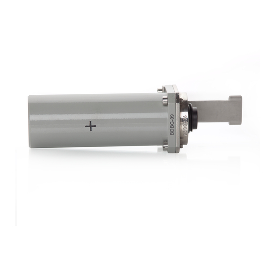
- Page 7 Operating manual ВІСТ.418266.006-03 НЕ 1.4 Design and operation principle of the detecting unit 1.4.1 Design description Appearance of the detecting unit with the connected cable is shown in Figure 1 (a): - detecting unit (1), - connecting cable (2), - detent (3) and corbel (4) to attach to the wall. Figure 1 (a) Alternatively, the detecting unit can be fastened to the surface where it will be directly installed is shown in Figure 1 (b).
- Page 8 Operating manual ВІСТ.418266.006-03 НЕ The case of the detecting unit (according to Figure 2) consists of two parts: a base (1) and a barrel (2). A printed-circuit board (3), with electric circuit elements placed on it, is attached with its bottom part to the base (1).
- Page 9 Operating manual ВІСТ.418266.006-03 НЕ 1.5 Measuring instruments, tools and equipment 1.5.1 A list of measuring instruments, tools and equipment necessary for control, setting and current repair of the detecting unit is presented in the Table 1.2. Table 1.2 – List of measuring instruments, tools and equipment Standardized document or main technical Name requirements...
-
Page 10: Proper Use
No.1 “Fragile – Handle with care”, No.3 “Protect from humidity”, No.11 “This side up”. The type of the detecting unit (BDBG-09) and the number of the detecting units in packing box is labeled under the main letterings. - Page 11 Operating manual ВІСТ.418266.006-03 НЕ 2.2.2.2 Before using the detecting unit that was on temporary closing-down, re-activate it and check its operability. 2.2.2.3 Register the re-activation and putting the detecting unit in operation in the logbook. 2.2.3 Guidelines on switching on and testing the detecting unit with description of testing procedure of the detecting unit in operation 2.2.3.1 Prepare the PC-based data display system for operation.
- Page 12 Operating manual ВІСТ.418266.006-03 НЕ Table 2.1 (continued) Trouble Probable cause Troubleshooting 2 Information evidence of the 2 Failure of the high 2 Send the detecting unit for high sensitivity detector failure sensitivity detector, which is repair to the repair services or (D0 bit is set in the byte of the a part of the detecting unit to the producer enterprise...
-
Page 13: Maintenance
Operating manual ВІСТ.418266.006-03 НЕ 3 MAINTENANCE 3.1 Technical maintenance of the detecting unit 3.1.1 General instructions The list of operations during technical maintenance (hereinafter the TM) of the detecting unit, order and peculiarities of operational phases are given in the Table 3.1. Table 3.1 –... - Page 14 Operating manual ВІСТ.418266.006-03 НЕ To deactivate, wipe thoroughly the contaminated areas with a cloth moistened with decontamination solution, then with a cloth moistened with warm water and wipe dry. Notes 1 Before deactivating the detecting unit, put on cotton gloves and rubber (surgical) gloves, observing safety requirements for operation with chemical solutions.
- Page 15 Operating manual ВІСТ.418266.006-03 НЕ Table 3.2 – Testing operations Operation name Testing procedure No. 1 External examination 3.2. 4.1 2 Testing 3.2. 4.2 3 Calculation of basic relative permissible error limits at gamma 3.2.4.3 radiation DЕR measurement 3.2.2 Testing facilities The following measuring instruments and equipment should be used during testing: - УПГД-3В...
- Page 16 Operating manual ВІСТ.418266.006-03 НЕ 3.2.4.2 Testing The detecting unit should be tested according to 2.2.3. 3.2.4.3 Calculation of basic relative error at gamma radiation DER measurement 3.2.4.3.1 Prepare the УПГД-3В standard equipment of gamma radiation for operation. 3.2.4.3.2 Fix the detecting unit in the УПГД-3В carriage holder, so that the mechanical center of gamma quanta beam coincides with the center of detectors.
- Page 17 Operating manual ВІСТ.418266.006-03 НЕ 3.2.4.3.11 Calculate the limit of relative residual bias of measurement results by the formula: − (3.5) ...
- Page 18 Operating manual ВІСТ.418266.006-03 НЕ 3.2.4.3.19 Perform operations 3.2.4.3.16 of the OM for gamma radiation DER from H source with the value of = (8010) mSv/h. 3.2.4.3.20 Perform operations 3.2.4.3.16 of the OM for gamma radiation DER from H source with the value of = (800100) mSv/h.
- Page 19 Operating manual ВІСТ.418266.006-03 НЕ 3.2.4.3.22.7 Set the CHANNEL switch of the switching desk to position "2" and repeat operation 3.2.4.3.22.6 with the difference that the value of ambient dose equivalent rate of gamma radiation of the measured frequency should be calculated by the formula: H ...
-
Page 20: Repair
4.1 The manufacturer performs repair of the detecting unit: PE “SPPE “Sparing-Vist Center” Tel.: (+38032) 242 15 15, fax: (+38032) 242 20 15 E-mail: sales@ecotest.ua. 5 STORAGE AND PUTTING IN PROLONGED STORAGE 5.1 Before putting in operation, the detecting unit should be stored in the packing of the producer enterprise in storehouses under conditions 1 (Л) according to ГОСТ... - Page 21 3 The technology software can operate on the IBM-compatible personal computer (PC) with installed Windows 98 and further versions of the operating system. 4 Connection of the BDBG-09 detecting unit to the PC, and power supply of the BDBG-09 is done with the help of USB <--> RS-485 interface adapter.
- Page 22 Operating manual ВІСТ.418266.006-03 НЕ For proper functioning of the bdbg.exe program set the minimum value of 1mS in the property of Latency Timer of the USB serial port. Do the following: open the Properties window: USB Serial Port (COM__);...
- Page 23 Operating manual ВІСТ.418266.006-03 НЕ - select the Port Settings tab. - click Advanced - change the value of Latency Timer (ms); - complete the input by clicking ОК.
- Page 24 Operating manual ВІСТ.418266.006-03 НЕ 6.2 Installing bdbg.exe program To install bdbg.exe, run the Setup.exe file from the installation disk's BDBG-09 folder and, in response to the setup program’s question, wait for the installation to complete. All the program files are copied to the directory <bootdrive>: \ Program Files \ SVC \ bdbg...
- Page 25 Notepad). The example of measurement results, saved with the help of the bdbg.exe program, is given in the Appendix C. The Light version indicator is used for operation with the BDBG-09 detecting unit version for everyday use without the low sensitivity detector.
- Page 26 BDBG-09 detecting units. In the event of operation with the current version of the BDBG-09 detecting unit, unselecting the checkbox will make it impossible to receive and send the calibration factors.
- Page 27 Operating manual ВІСТ.418266.006-03 НЕ - Measurement – clicking this button enables a user to start a continuous process of querying the detecting unit, receiving and displaying DER measurement results. Queries are sent to the detecting unit with one second interval. - Stop –...
- Page 28 Operating manual ВІСТ.418266.006-03 НЕ APPENDIX B COMMUNICATIONS PROTOCOL OF THE DATA DISPLAY SYSTEM AND THE DETECTING UNIT B.1 Data frames exchange between the detecting unit and the data display system is done via RS-485 interface in a half-duplex mode. Exchange parameters: - rate: 19,200 bps;...
- Page 29 Operating manual ВІСТ.418266.006-03 НЕ “DER query” frame format – the data display system to the detecting unit Byte 55h – start-of-frame character Byte AAh D7...D4 – “DER query” frame code А3 А2 А1 А0 D3...D0 – detecting unit address * * - 0Fh address –...
- Page 30 Operating manual ВІСТ.418266.006-03 НЕ “Temperature query” frame format – the data display system to the detecting unit (for the detecting units with embedded temperature detector) Byte 55h – start-of-frame character Byte AAh D7…D4 – “Temperature query” frame code А3 А2 А1 А0 D3…D0 –...
- Page 31 Operating manual ВІСТ.418266.006-03 НЕ “New factors” frame format –the data display system to the detecting unit Byte 55h – start-of-frame character Byte AAh D7…D4 – “New factors” frame code А3 А2 А1 А0 D3…D0 – detecting unit address mantissa high byte Multiplication factor of the high exponent sensitivity detector...
- Page 32 Operating manual ВІСТ.418266.006-03 НЕ “Current factors query” frame format –the data display system to the detecting unit Byte 55h – start-of-frame character Byte AAh D7…D4 – “Current factors query” frame code А3 А2 А1 А0 D3…D0 – detecting unit address “Factors”...
- Page 33 Operating manual ВІСТ.418266.006-03 НЕ “Serial # query” frame format – the data display system to the detecting unit Byte 55h – start-of-frame character Byte AAh D7…D4 – “Serial # query” frame code А3 А2 А1 А0 D3…D0 – detecting unit address * * - 0Fh address –...
- Page 34 Operating manual ВІСТ.418266.006-03 НЕ B.3.2 Communications protocol with the 8-digit address field (v1.3). To receive the measured value of DER from the detecting unit, the data display system should transmit the “DER1 query” frame to the detecting unit. The detecting unit will respond in 5 ms to 15 ms with the “Current DER1”...
- Page 35 Operating manual ВІСТ.418266.006-03 НЕ “DER1 query” frame format –the data display system to the detecting unit Byte 55h - start-of-frame character Byte AAh D7…D4–protocol v1.3 character address D7…D0– detecting unit address * D7…D0–“DER1 query” frame code control arithmetical checksum with a carry * - 0FFh address –...
- Page 36 Operating manual ВІСТ.418266.006-03 НЕ “Temperature1 query” frame format – the data display system to the detecting unit (for the detecting units with embedded temperature detector) Byte 55h – start-of-frame character Byte AAh D7…D4– protocol v1.3 character address D7…D0– detecting unit address* D7…D0–“Temperature1 query”...
- Page 37 Operating manual ВІСТ.418266.006-03 НЕ “New factors1” frame format –the data display system to the detecting unit Byte 55h – start-of-frame character Byte AAh D7…D4– protocol v1.3 character address D7…D0– detecting unit address D7…D0–“New factors1” frame code mantissa high byte Multiplication factor of the high exponent sensitivity detector mantissa low byte...
- Page 38 Operating manual ВІСТ.418266.006-03 НЕ “Confirmation1” frame format –the detecting unit to the data display system Byte 55h – start-of-frame character Byte AAh D7…D4– protocol v1.3 character address D7…D0– detecting unit address D6…D0–“Confirmation1” frame code D7 = 0 - normal operation D7 = 1 - error control arithmetical checksum with a carry...
- Page 39 Operating manual ВІСТ.418266.006-03 НЕ “Factors1” frame format – the data display system to the detecting unit Byte 55h - start-of-frame character Byte AAh D7…D4– protocol v1.3 character address D7…D0– detecting unit address D7…D0–“Factors1” frame code mantissa high byte Multiplication factor of the high exponent sensitivity detector mantissa low byte...
- Page 40 Operating manual ВІСТ.418266.006-03 НЕ “Serial #_1 query” frame format – the data display system to the detecting unit Byte 55h – start-of-frame character Byte AAh D7…D4– protocol v1.3 character address D7…D0– detecting unit address* D7…D0–“Serial#_1 query” frame code control arithmetical checksum with a carry * - 0FFh address –...
- Page 41 Operating manual ВІСТ.418266.006-03 НЕ “Address1 change” frame format – the data display system to the detecting unit Byte 55h – start-of-frame character Byte AAh D7…D4– protocol v1.3 character D7…D0– current address of the detecting current address unit D7…D0–“Address1 change” frame code new address D7…D0–...
- Page 42 Operating manual ВІСТ.418266.006-03 НЕ B.4 Checksum for data communications using both v1.2 protocol, and v1.3 protocol is calculated according to Figure B.1. byte arithmetical summation checksum partial result carry arithmetical summation carry checksum Figure B.1 – Checksum calculation algorithm...
- Page 43 Operating manual ВІСТ.418266.006-03 НЕ B.5 CA6GS 932326-100 HIRSCHMANN interface connection serves to connect the data display system to the detecting unit. The interface connection contains the following signals: Signal contact (RS-485) Circuit A (RS-485) Circuit B Reserve Supply voltage Total Shield Shield...
- Page 44 ---------------------------------------------------------------------------------------------------- Date Time Measured Dose Rate Max. stat. error Tests results Temperature ---------------------------------------------------------------------------------------------------- BDBG-09 #0308123 Response delay factor to broadcast query:1 06.04.2009 15:14:27 Factors received from detecting unit HIGH SENSITIVE DETECTOR: Multiplication factor: 0,33 Dead time (formula): Dead time (physical):...
- Page 45 UNIT TO DATA DISPLAY SYSTEM To provide stable operation of the BDBG-09 detecting unit, and stable data communications between the BDBG-09 detecting unit and the data display system, you should use the cable with the following parameters: - number of twisted pairs: not less than 2 (pairs not in use should be connected to minus of power supply from the side, where power is supplied to the cable);...
- Page 46 Operating manual ВІСТ.418266.006-03 НЕ APPENDIX E Anisotropy of the BDBG-09 (vertical plane) Cs-137 СО-60 Ам-241 Cs - 137 Ам -241 Co- 60 -100 Anisotropy of Cs-137 the BDBG-09 СО-60 (horizontal plane) Ам-241 Ам -241 Co- 60 -100 Cs - 137...
Need help?
Do you have a question about the BDBG-09 and is the answer not in the manual?
Questions and answers