Table of Contents
Advertisement
Quick Links
Advertisement
Table of Contents

Related Manuals for ECOTEST MKS-05 TERRA


Summary of Contents for ECOTEST MKS-05 TERRA
- Page 1 MKS-05 “TERRA” DOSIMETER-RADIOMETER Operating manual...
-
Page 2: Table Of Contents
CONTENTS 1 DESCRIPTION AND OPERATION............4 1.1 P ................4 URPOSE OF USE 1.2 T ............5 ECHNICAL SPECIFICATIONS 1.3 D ................18 ELIVERY KIT 1.4 D .......... 20 ESIGN AND PRINCIPLE OF OPERATION 1.5 L ............... 25 ABELING AND SEALING 1.6 P .................. - Page 3 5 PACKING CERTIFICATE ..............128 6 WARRANTY ..................129 7 REPAIR..................... 130 8 STORAGE..................132 9 SHIPPING ..................133 10 DISPOSAL ..................134 APPENDIX А..................135 APPENDIX B..................137 APPENDIX C..................139 APPENDIX D..................140 APPENDIX E ..................141 APPENDIX F ..................142 APPENDIX G..................
- Page 4 This operating manual (hereinafter called the OM) is intended to inform the user about the principles of operation and rules of application of the MKS-05 “TERRA” dosimeter-radiometer. The manual contains all information necessary for proper use of the dosimeter and full realization of its technical possibilities.
-
Page 5: Description And Operation
1 DESCRIPTION AND OPERATION 1.1 Purpose of use The MKS-05 “TERRA” dosimeter-radiometer (hereinafter called the dosimeter) is designed to measure ambient dose equivalent (DE) and ambient dose equivalent rate (DER) of gamma and X-ray radiation (hereinafter called photon-ionizing radiation), and surface beta-particles flux density. -
Page 6: Technical Specifications
1.2 Technical specifications 1.2.1 Key specifications are presented in Table 1.1. Table 1.1 – Key specifications Standardized values Unit of Name according to technical measurement specifications 1 Measurement range of photon- μSv/h 0.1 – 9999 ionizing radiation DER 2 Main relative permissible error ... - Page 7 Table 1.1 (continued) Standardized values Unit of Name according to technical measurement specifications 4 Main relative permissible error limit of photon-ionizing radiation ±15 DE measurement with confidence probability of 0.95 5 Energy range of registered 0.05 – 3.00 photon-ionizing radiation 6 Energy dependence of the dosimeter readings at photon- ionizing radiation DER and DE...
- Page 8 Table 1.1 (continued) Standardized values Unit of Name according to measurement technical specifications 7 Anisotropy of the dosimeter at gamma quantum incidence at solid angle of 30 relative to the main axis of the detector and from the side of the main measurement direction for: 25 - 137...
- Page 9 Table 1.1 (continued) Unit of Standardized values according to Name measurement technical specifications 9 Main relative permissible error 20 limit of beta- where is a numeric value of the φ particles flux density β measurement with measured surface flux density in confidence part./(cm ·min)
- Page 10 Table 1.1 (continued) Standardized values Unit of according to Name measurement technical specifications 12 Resolution of DE accumulation time display in the range 1 min of 0 h to 100 hrs of 100 hrs to 9999 hrs 13 Absolute permissible error limit at DE accumulation time ±1 measurement during 24 hrs...
- Page 11 Table 1.1 (continued) Standardized values Unit of Name according to measurement technical specifications 15 Battery life (AAAx2 of 1280 mA·h о capacity) under + 20 С temperature, natural 1500 background radiation and switched off display backlight, not more than 16 Unstable readings of the dosimeter for 6 hours of continuous operation, not more than 17 Operating supply voltage of the dosimeter 18 Additional permissible error limit at...
- Page 12 Table 1.1 (continued) Standardized Unit of values according Name measur to technical ement specifications 19 Additional permissible error limit at measurement of photon-ionizing radiation DE and DER and surface beta-particles flux ±5 density in the ambient air temperature range of о...
- Page 13 Table 1.1 (continued) Standardized Unit of values according Name measureme to technical specifications 24 Average shelf life of the dosimeter, not year less than 25 Dimensions, not more than 5526120 26 Weight, not more than 1.2.2 The dosimeter displays the statistical error value of measurement result of photon-ionizing radiation DER and surface beta-particles flux density.
- Page 14 1.2.4 For fast evaluation of photon-ionizing radiation DER and surface beta-particles flux density the dosimeter provides a ten-segment indicator of instantaneous value. The information is updated on the indicator of instantaneous value each 500 ms. 1.2.5 Threshold alarm system with three independent threshold levels is realized in the dosimeter: - photon-ionizing radiation DER;...
- Page 15 1.2.5.3 Threshold level values of surface beta-particles flux density in the range of 0 to 9999·10 part./(cm ·min) with discreteness of 0.0110 part./(cm ·min) are programmed in the dosimeter. 1.2.5.4 The programmed values of the threshold levels are saved in the nonvolatile memory of the dosimeter, and are not changed when the dosimeter is turned on/off or the batteries are replaced.
- Page 16 1.2.8 The dosimeter stores up to 1200 measurement results of photon- ionizing radiation DER or surface beta-particles flux density in its nonvolatile memory. For more convenient identification every measurement result is stored along with a three-digit number of measurement object, as well as with time and date of measurement.
- Page 17 1.2.12 The dosimeter provides the possibility to work in the mode of intelligent detecting unit (hereinafter called the IDU). In this mode the dosimeter sends to the PC via the Bluetooth radio channel: - current measurement results of photon-ionizing radiation DER or surface beta-particles flux density;...
- Page 18 1.2.15 The dosimeter is resistant to the following external factors: - high frequency sinusoidal vibrations (with crossover frequency from 57 to 62 Hz) in the range of 10 to 55 Hz, 0.15 mm bias for frequency lower than the crossover frequency; - shocks with a shock pulse duration of 5 ms, a total number of shocks 1000±10 and maximum acceleration of 100 m/s - shocks in shipping container with an acceleration of 98 m/s...
-
Page 19: Delivery Kit
1.3 Delivery kit 1.3.1 The delivery kit of the dosimeter consists of the items and the maintenance documentation presented in Table 1.2. Table 1.2 - Delivery kit of the dosimeter Type Item Quantity Note Bluetooth MKS-05 “TERRA” radio ВІСТ.412129.006-09 dosimeter- channel radiometer included... - Page 20 Table 1.2 (continued) Type Item Quantity Note Art. 80311 ТУ У Leather case 1 pc. 31111166.001- 2001 Custom-made software “Computer- Supplied with the aided programming devices equipped and operation logging with Bluetooth of the dosimeter ” channel (“Cadmium- ECOMONITOR”)
-
Page 21: Design And Principle Of Operation
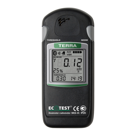
1.4 Design and principle of operation 1.4.1 Design of the dosimeter The dosimeter is designed as a flat square plastic body with rounded corners. The body (Figure 1) consists of the upper (1) and the lower (2) covers. The LCD (3) is located in the middle of the upper cover (2); two keys of control –... - Page 22 Figure 1 – External view of the dosimeter (top view)
- Page 23 Figure 2 - External view of the dosimeter (bottom view)
- Page 24 The battery compartment (1) and the window (3) for surface beta- particles flux density measurement are located in the lower cover (7) (Figure 2). The battery compartment (1) is closed with the cover (2) whereas the window of the detector (3) is closed with the filter cover, both of which are fastened due to the elastic capacities of the material.
- Page 25 The gamma and beta radiation detector built on the basis of СБМ-20-1 Geiger-Muller counter, transforms radiation into the sequence of voltage pulses; the number of pulses per unit of time is proportional to the registered radiation intensity. The circuit of the anode voltage formation and the circuit of digital processing, control and indication provide: - generation and regulation of the detector anode voltage;...
-
Page 26: Labeling And Sealing
1.5 Labeling and sealing 1.5.1 The upper cover of the dosimeter is inscribed with the name, the symbol of the device, the trademark of the producer enterprise, the ingress protection rating of the dosimeter, and the pattern approval mark of measuring instruments A serial number and a manufacture date are inscribed on the lower cover. -
Page 27: Proper Use
2 PROPER USE 2.1 Operating limitations Operating limitations are presented in Table 2.1. Table 2.1 – Operating limitations Operating limitations Limitation parameters о 1 Ambient air temperature from - 25 to +55 С о up to 95 % at + 35 С... - Page 28 2.2.2 Rules and order of examination for operational readiness. 2.2.2.1 Study the operating manual before putting the dosimeter into operation. 2.2.2.2 Open the battery compartment and make sure the two batteries are inserted, connections are reliable, and there is no leakage of salts after durable storage of the dosimeter.
- Page 29 2.2.3.2 Press shortly the MODE button and make sure the dosimeter has entered the mode of indication of photon-ionizing radiation DE accumulated value. “γ” symbol and “mSv” dimension of the measured quantity show that the dosimeter is operating in this mode. 2.2.3.3 Press shortly the MODE button and make sure the dosimeter enters the mode of surface beta-particles flux density measurement.
- Page 30 Table 2.2 – Possible troubles and troubleshooting Trouble Probable cause Troubleshooting The dosimeter 1 The batteries are 1 Replace the batteries does not switch discharged on after the MODE button is 2 No contact between 2 Restore the contact pressed the batteries and the between the batteries and battery compartment...
- Page 31 Table 2.2 (continued) Trouble Probable cause Troubleshooting Low battery 1 Poor contact between 1 Clean out the indication is the batteries and the contacts on the clamps displayed on the battery compartment and the batteries LCD after the clamps batteries have been replaced 2 One of the batteries is 2 Replace the defected...
- Page 32 Table 2.2 (continued) Trouble Probable cause Troubleshooting No connection between 1 The distance 1 Make the distance the dosimeter and the between the between the PC, which is testified dosimeter and the PC dosimeter and the PC by the messages is too big smaller “Er03”, “Er04”,...
-
Page 33: Use Of The Dosimeter
2.3 Use of the dosimeter 2.3.1 Safety measures during use of the dosimeter 2.3.1.1 The dosimeter contains no external parts exposed to voltages hazardous for life. 2.3.1.2 Direct use of the device is not dangerous for the service personnel and is environmentally friendly. 2.3.1.3 A special protective jacket is used to prevent accidental contact with conductive parts. - Page 34 2.3.2 Operating modes of the dosimeter 2.3.2.1 Operating modes of the dosimeter The dosimeter operates within the following modes: - photon-ionizing radiation DER measurement; - indication of accumulated value of photon-ionizing radiation DE; - surface beta-particles flux density measurement; - clock; - alarm clock;...
- Page 35 - programming of new values of audio alarm threshold level and specified statistical error, and switching on/off audio signaling of registered gamma-quanta. The mode of accumulated value indication of photon-ionizing radiation DE consists of the following submodes: - programming of a new value of audio alarm threshold level; - resetting the values of DE and DE accumulation time.
- Page 36 The mode of clock has the submode of time and date correction. The mode of alarm clock has the submode of programming the time of alarm activation. The mode of measurement results viewing stored in the nonvolatile memory has the submode of measurement results clearing. 2.3.3 Operation procedure of the dosimeter 2.3.3.1 Dosimeter’s buttons The THRESHOLD (4) and the MODE (5) buttons are used to operate...
- Page 37 2.3.3.2 Switching the dosimeter on/off Press shortly the MODE button to switch the dosimeter on. A short vibration-audio signal and symbols displayed on the LCD show that the dosimeter is on. Press the MODE button once again and hold it pressed for circa six seconds to switch the dosimeter off.
- Page 38 - the mode of accumulated value indication of photon-ionizing radiation DE; - the mode surface beta-particles flux density measurement; - the mode of clock; - the mode of alarm clock; - the mode of data communications control with the PC; - the mode of measurement results viewing stored in the nonvolatile memory (if such results exist).
- Page 39 If the nonvolatile memory has no saved measurement results, a short press of the MODE button switches the dosimeter from the mode of data communications control with the PC directly to the mode of photon-ionizing radiation DER measurement. A short or a long press of the THRESHOLD button in any operating mode of the dosimeter changes the submodes of this operating mode.
- Page 40 Figure 3 – LCD of the dosimeter (the mode of photon-ionizing radiation DER measurement)
- Page 41 2.3.3.5 LCD backlight control Each press of any button of the dosimeter activates the LCD backlight for 6 seconds. Press the THRESHOLD button twice (time between presses should not exceed 0.5 s) to turn on a continuous LCD backlight. Press the THRESHOLD button twice once again to turn off a continuous LCD backlight.
- Page 42 2.3.3.7 The mode of photon-ionizing radiation DER measurement The mode of photon-ionizing radiation DER measurement is entered automatically after the dosimeter is switched on. With a short press on the MODE button you can proceed to this mode from any other operating mode. To measure photon-ionizing radiation DER, direct the dosimeter with its metrological mark “+”...
- Page 43 battery status symbol (7); measurement result (8); dimension of measurement result (9); current time (10); threshold level of alarm actuation (11). As soon as the measurement is started the measurement results of photon-ionizing radiation DER (8) and the statistical error values (1) that correspond to these results begin to be formed on the LCD.
- Page 44 The ten-segment indicator of instantaneous value (3) is used for fast evaluation of photon-ionizing radiation intensity. The integration time during measurement of the instantaneous intensity value and the time of information update on the instantaneous value indicator are equal to 500 ms. The instantaneous intensity value is displayed in pseudo-logarithmic scale.
- Page 45 Audio signaling of registered gamma quanta is switched on and off in the submode of alarm threshold level programming. Photon-ionizing radiation DER is measured in the following way. As soon as the measurement is started the LCD of the dosimeter begins to display the measurement results and the statistical error values that correspond to these results.
- Page 46 If the specified statistical error is determined automatically by the device, its value is blinking on the LCD until it remains greater than the value of main relative permissible error limit of photon-ionizing radiation DER measurement (Table 1.1). If the specified statistical error is determined by the user, its value is blinking on the LCD until it remains greater than the value of the specified statistical error.
- Page 47 Figure 4 – LCD of the dosimeter (viewing the value of specified statistical error)
- Page 48 If the THRESHOLD button is being held down for more than three seconds, the LCD displays the “Arch” symbols (Figure 5). Thus it becomes possible to proceed to the submode of measurement result saving in the nonvolatile memory. Figure 5 – LCD of the dosimeter (start of the submode of measurement result saving in the nonvolatile memory)
- Page 49 If you keep holding the THRESHOLD button, the “Arch” symbols will disappear from the LCD, and the measurement will be restarted during the next two seconds (Figure 6). Figure 6 – LCD of the dosimeter (measurement restart)
- Page 50 If you keep holding the THRESHOLD button, then during the next two seconds the dosimeter will proceed to the submode of programming of new values of alarm threshold level and specified statistical error, and switching on/off audio signaling of registered gamma-quanta (Figure 7). A stripe (1) “moving”...
- Page 51 Figure 7 – LCD of the dosimeter (the submode of alarm threshold level programming)
- Page 52 A short press of the MODE button fixes the value of the digit (it stops blinking) and allows presetting the value of the next digit, which starts blinking at that. Other digits are programmed likewise. As soon as all digits of the new threshold level are programmed, the LCD of the dosimeter displays the specified statistical error (Figure 8).
- Page 53 Figure 8 – LCD of the dosimeter (the submode of alarm threshold level programming)
- Page 54 As soon as all digits of the new value of the specified statistical error are programmed, the sound symbol starts blinking on the LCD of the dosimeter. Thus it becomes possible to switch on/off audio and/or vibration signaling of every registered gamma quantum. Successive short presses of the THRESHOLD button switches the alarm on/off.
- Page 55 audio signaling of registered gamma-quanta is paused for more than 30 s (the user presses no buttons of the dosimeter), the dosimeter will automatically return to the mode of photon-ionizing radiation DER measurement. All changes made in the submode of new values programming will be cancelled.
- Page 56 Figure 9 – LCD of the dosimeter (start of the submode of measurement result saving – no free space in the nonvolatile memory)
- Page 57 To clear the space in the nonvolatile memory, delete its saved measurement results. Measurement results can be cleared during data communications with the PC (2.3.3.12 of the OM) or in the viewing mode (2.3.3.13 of the OM). The “Arch” symbols (1) on the LCD of the dosimeter are an indication of the submode of measurement result saving (Figure 10).
- Page 58 Figure 10 – LCD of the dosimeter (the submode of measurement result saving of photon-ionizing radiation DER)
- Page 59 The low-order digit of the object number is blinking and shows that its value can be programmed. Use the THRESHOLD button to set the required value of the blinking digit. Successive short presses and releases of the THRESHOLD button change this value per unit. A long press of the THRESHOLD button starts automatic change of this value, which is stopped after the button is released.
- Page 60 dosimeter will automatically return to the mode of photon-ionizing radiation DER measurement without saving the measurement result. 2.3.3.8 The mode of indication of photon-ionizing radiation DE accumulated value This mode can be entered from any other operating mode of the dosimeter with the help of a short press of the MODE button.
- Page 61 Figure 11 – LCD of the dosimeter (the mode of indication of photon-ionizing radiation DE accumulated value)
- Page 62 The accumulated value of photon-ionizing radiation DE, DE accumulation time and DE threshold level are displayed in this mode. The process of photon-ionizing radiation DE accumulation starts right after the dosimeter is switched on, and is performed in all operating modes, except for surface beta-particles flux density measurement.
- Page 63 As soon as DE accumulation time exceeds 100 hours, it is displayed in the “HHHH” format, where HHHH stands for the value of hours of DE accumulation time. The “:” symbol is absent. The dosimeter sends a two-tone audio signal and/or an intermittent vibration signal when the measured DE value of alarm threshold level is exceeded, depending on the chosen alarm type.
- Page 64 Figure 12 – LCD of the dosimeter (the submode of a new value programming of alarm threshold level)
- Page 65 When a digit is blinking, it means that its value can be programmed. Use the THRESHOLD button to set the required value of the blinking digit. Successive short presses and releases of the THRESHOLD button change this value per unit. A long press of the THRESHOLD button starts automatic change of this value, which is stopped after the button is released.
- Page 66 Caution! If the submode of a new value programming of alarm threshold level is paused for more than 30 s (the user presses no buttons of the dosimeter), the dosimeter will automatically return to the mode of indication of photon-ionizing radiation DE accumulated value. All changes made in the submode of a new value programming will be cancelled.
- Page 67 Figure 13 – LCD of the dosimeter (the sumbode of DE and DE accumulation time values resetting)
- Page 68 To cancel resetting, shortly press the THRESHOLD button once again or do not press the buttons during 30 s (the dosimeter will automatically enter the mode of indication of photon-ionizing radiation DE accumulated value and DE accumulation time). To confirm resetting of DE and DE accumulation time values, shortly press the MODE button.
- Page 69 2.3.3.9 The mode surface beta-particles flux density measurement This mode can be entered from any other operating mode of the dosimeter with the help of a short press of the MODE button. This mode follows the mode of measured value indication of photon-ionizing radiation DE and DE accumulation time.
- Page 70 To measure surface beta-particles flux density, remove the filter cover from the window, located opposite the detector, direct the dosimeter with the window in parallel to the examined surface and place it as close as possible. In the mode of surface beta-particles flux density measurement the dosimeter’s LCD displays the following information (Figure 14): - statistical error (1) of the measurement result (8);...
- Page 71 Figure 14 – LCD of the dosimeter (the mode of surface beta-particles flux density measurement)
- Page 72 As soon as the measurement is started the surface beta-particles flux density measurement results (8) and the statistical error values (1) that correspond to these results begin to be formed on the LCD. If the flux density measurement results exceed the alarm threshold level (11), the dosimeter sends a two-tone audio signal and/or an intermittent vibration signal, which depends on the chosen alarm type.
- Page 73 The greater the intensity becomes the more scale segments start to be highlighted from left to right. The scale becomes fully highlighted when the intensity equals to 740 pulse/s pulse rate from the Geiger-Muller counter. Beta-particles flux density is about 4510 part./(cm min) in this case if gamma background is not increased.
- Page 74 If this error is reached, a part of statistical information starts to be rejected while the measurement process continues. Therefore, all following measurement results will have the statistical error, which is equal to or less than the specified one. The dosimeter can automatically determine the specified statistical error depending on the radiation intensity (Appendix C).
- Page 75 THRESHOLD button is being pressed and held down (but not longer than 3 s). A zero value display means that the dosimeter determined the specified statistical error automatically depending on the radiation intensity. Figure 15 – LCD of the dosimeter (viewing the value of specified statistical error)
- Page 76 If the THRESHOLD button is being held down for more than three seconds, the LCD displays the “Arch” symbols (Figure 16). Thus, it becomes possible to proceed to the submode of measurement result saving in the nonvolatile memory. Figure 16 – LCD of the dosimeter (start of the submode of measurement result saving in the nonvolatile memory)
- Page 77 If you keep holding the THRESHOLD button, the “Arch” symbols will disappear from the LCD, and the measurement will be restarted during the next two seconds (Figure 17). Figure 17 – LCD of the dosimeter (measurement restart)
- Page 78 If you keep holding the THRESHOLD button, then during the next two seconds the dosimeter will proceed to the submode of new values programming of alarm threshold level and specified statistical error, and switching on/off audio signaling of registered gamma-quanta and beta- particles (Figure 18).
- Page 79 Figure 18 – LCD of the dosimeter (the submode of alarm threshold level programming)
- Page 80 Proceeding to the submode of measurement result saving should be confirmed by a short press of the MODE button. Press shortly the THRESHOLD button to cancel the action. If the buttons are not pressed for 30 s, the dosimeter automatically returns to the mode of surface beta- particles flux density measurement.
- Page 81 Figure 19 – LCD of the dosimeter (start of the submode of measurement result saving – no free space in the nonvolatile memory)
- Page 82 The “Arch” symbols (2) on the LCD of the dosimeter are an indication of the submode of measurement result saving (Figure 20). In this submode the LCD displays the measurement result (1) and the measurement object number (3) that will be saved in the nonvolatile memory. The nonvolatile memory status is displayed on the instantaneous value indicator (4).
- Page 83 Figure 20 – LCD of the dosimeter (the submode of measurement result saving of surface beta-particles flux density)
- Page 84 2.3.3.10 The clock mode This mode can be entered from any other operating mode of the dosimeter with the help of a short press of the MODE button. This mode follows the mode of surface beta-particles flux density measurement. In the mode of clock the dosimeter’s LCD displays the following information (Figure 21): alarm clock symbol (1) (if the alarm clock is on);...
- Page 85 Figure 21 – LCD of the dosimeter (the clock mode)
- Page 86 To proceed to the submode of time and date correction, press and hold the THRESHOLD button until a stripe (1) “moving” across the instantaneous value indicator appears on the LCD, and the digits of minutes (2) start blinking (Figure 22). Figure 22 –...
- Page 87 When digits are blinking, it means that their values can be programmed. Use the THRESHOLD button to set the required value of the digit. Successive short presses and releases of the THRESHOLD button change this value per unit. A long press of the THRESHOLD button starts automatic change of this value, which is stopped after the THRESHOLD button is released.
- Page 88 Figure 23 – LCD of the dosimeter (the submode of time and date correction – year programming)
- Page 89 When the low-order digits of the year are blinking, it means that their values can be programmed. They are programmed with the help of the THRESHOLD button in a similar way to the minute digits programming. The year value can be set within the limits from 2010 to 2099. A short press of the MODE button fixes a new value of year in the dosimeter’s memory.
- Page 90 Figure 24 – LCD of the dosimeter (the submode of time and date correction – date programming)
- Page 91 A short press of the MODE button fixes the values of the month digits (they stop blinking) and allows presetting the values of the date digits, which start blinking at that. The date digits are programmed with the help of the THRESHOLD button in a similar way to the hour digits programming.
- Page 92 2.3.3.11 The mode of alarm clock This mode can be entered from any other operating mode of the dosimeter with the help of a short press of the MODE button. This mode follows the mode of clock. In the mode of alarm clock the dosimeter’s LCD displays the following information (Figure 25): - alarm clock symbol (1) (if the alarm clock is on);...
- Page 93 Figure 25 – LCD of the dosimeter (the alarm clock mode)
- Page 94 Figure 26 – LCD of the dosimeter (the submode of alarm clock activation time programming)
- Page 95 Minutes and hours of the alarm clock activation are programmed in a similar way to time correction in the clock mode. As soon as the alarm clock activation time is programmed, the alarm clock symbol (2) starts blinking on the LCD of the dosimeter. Thus it becomes possible to turn on/off the alarm clock ringing at a time set in advance.
- Page 96 If the alarm clock is on, and the current time coincides with the alarm clock activation time, the alarm clock will be activated and the dosimeter will start generating the alarm clock signal – typical audio and/or vibration signals, in all operating modes and submodes of the dosimeter, except for the submode of time and date correction.
- Page 97 2.3.3.12 The mode of data communications control with the PC 2.3.3.12.1 This mode can be entered from any other operating mode of the dosimeter with the help of a short press of the MODE button. This mode follows the alarm clock mode. In the mode of data communications control with the PC the dosimeter’s LCD displays the following information (Figure 27): - alarm clock symbol (1) (if the alarm clock is on);...
- Page 98 Figure 27 – LCD of the dosimeter (the mode of data communications control with the PC)
- Page 99 If the connection failed to be established or data communications failed to be performed with the PC (for instance, the PC is off, located beyond the reach of the Bluetooth radio channel of the dosimeter, or the custom-made software is not launched on this PC), the dosimeter is searching for the PC with a Bluetooth name starting with the “CHECKPOINT”...
- Page 100 Figure 28 – LCD of the dosimeter (the mode of data communications control with the PC)
- Page 101 During the data communications the dosimeter can operate in the mode of IDU. The dosimeter sends to the PC: - current measurement results of photon-ionizing radiation DER or surface beta-particles flux density; - current value of accumulated photon-ionizing radiation DE, and DE accumulation time;...
- Page 102 communications with the PC can be stopped only with the help of the controls of the custom-made software „Computer-aided programming and operation logging of the dosimeter” („Cadmium-ECOMONITOR”). 2.3.3.13 The mode of measurement results viewing stored in the nonvolatile memory 2.3.3.13.1 If the nonvolatile memory of the dosimeter contains measurement results, this mode can be entered from any other operating mode of the dosimeter with the help of a short press of the MODE button.
- Page 103 Figure 29 – LCD of the dosimeter (the mode of measurement results viewing stored in the nonvolatile memory)
- Page 104 Press shortly the THRESHOLD button to view the measurement results stored in the nonvolatile memory. The LCD of the dosimeter displays the following information (Figure 30): indicator of measurement results location in the nonvolatile memory (1); alarm clock symbol (2) (if the alarm clock is on); alarm type symbol (3);...
- Page 105 Figure 30 – LCD of the dosimeter (measurement results viewing)
- Page 106 The indicator of location (1) shows a place of the measurement result (5) in the nonvolatile memory. The leftmost position of the location indicator corresponds to the start of the nonvolatile memory, i.e. the oldest measurement result (the measurement result that was first saved). The rightmost position corresponds the end of the nonvolatile memory, i.e.
- Page 107 A short press on the THRESHOLD button makes it possible to view the previous measurement result that has been saved before the measurement result, which is displayed on the LCD now. The LCD of the dosimeter displays the measurement object number and the time of measurement performance along with each measurement result.
- Page 108 Figure 31 – LCD of the dosimeter (the submode of measurement results clearing stored in the nonvolatile memory)
- Page 109 To cancel clearing, shortly press the THRESHOLD button or do not press the buttons during 30 s (the dosimeter will automatically enter the mode of measurement results viewing stored in the nonvolatile memory). To confirm clearing of the measurement results stored in the nonvolatile memory, shortly press the MODE button.
-
Page 110: Technical Maintеnance
3 TECHNICAL MAINTЕNANCE 3.1 Technical maintenance of the dosimeter 3.1.1 General instructions The list of operations performed during technical maintenance (hereinafter called TM) of the dosimeter, the order and the peculiarities of operational phases are presented in Table 3.1. Table 3.1 – List of operations during technical maintenance TM type during OM item... - Page 111 Note. “+” means the operation is applicable for this type of TM; “-” means the operation is not applicable. 3.1.2 Safety measures TM safety measures fully comply with safety measures stated in item 2.3.1 of the present OM. 3.1.3 Maintenance procedure of the dosimeter 3.1.3.1 External examination External examination of the dosimeter should be performed in the...
- Page 112 3.1.3.3.2 Order of pre-repair fault detection and rejection Use the following criteria to evaluate the necessity of sending the dosimeter for repair and the type of repair: - for mid-life repair: а) deviation of parameters from reference values during the periodical verification of the dosimeter;...
-
Page 113: Erification Of The Dosimeter
3.1.3.4 Batteries switching off and their status control The batteries should be switched off each time before the long-term storage of the dosimeter. Do this as follows: - switch the dosimeter off; - open the lid of the battery compartment; - remove the batteries;... - Page 114 Table 3.2 – Verification operations Verification Operation name technique No. External examination 3.2.4.1 Testing 3.2.4.2 Calculation of main relative error of photon-ionizing 3.2.4.3 radiation DER measurement Calculation of main relative error of photon-ionizing 3.2.4.4 radiation DE measurement Calculation of main relative error of beta particles 3.2.4.5 flux density measurement 3.2.2 Verification facilities...
- Page 115 - low-active gamma radiation source - standard stop-watch All verification facilities should obtain valid Verification Certificates or State Metrological Certification Note. Use of other standard measuring equipment with the accuracy prescribed in 3.2.2 is allowed. 3.2.3 Verification conditions Verification should be performed in compliance with the following conditions: - ambient air temperature range within (20±5) °C;...
- Page 116 3.2.4 Verification procedure 3.2.4.1 External examination During external examination the dosimeter should meet the following requirements: - the delivery kit should be completed as stated in item 1.3.1 of the present OM; - labeling should be accurate; - Quality Control Department seals should not be violated; - the dosimeter should be free from mechanical damage that may affect its performance.
- Page 117 3.2.4.3 Calculation of main relative error of photon-ionizing radiation DER measurement Prepare the УПГД-3В testing equipment for operation according to its operating manual. Prepare the dosimeter for photon-ionizing radiation DER measurement (hereinafter called DER) and program 5 % value of the specified statistical error according to item 2.3.3.7 of the OM.
- Page 118 H Calculate the DER value , in µSv/h by the formula: Ф where H - is an average value of the dosimeter readings of source and external gamma background in µSv/h; H ...
- Page 119 Place the УПГД-3В carriage together with the dosimeter in the position, where DER from Cs source is 80.0 µSv/h, and wait until the statistical error of DER measurement results goes down to the value of not more than 10 %. Then register five DER measurement results in the protocol with 5 s interval.
- Page 120 more than 10 %. Then register five DER measurement results in the protocol with 5 s interval. Calculate the average DER value and the main relative error of measurement in percentage. The dosimeter is acknowledged to have passed the verification if the main relative error in percentage during measurement of each DER level H ...
- Page 121 Place the УПГД-3В carriage together with the dosimeter in the position, where DER from Cs source is 80 µSv/h. Record the initial DE value and simultaneously switch on the stop-watch. Read the DE measurement result after 60 minutes (according to the stop-watch) of irradiation, subtract the DE initial value, calculate the main relative error of measurement in percentage, and register these values in the protocol.
- Page 122 Record the initial DE value and simultaneously switch on the stop-watch. Read the DE measurement result after 10 minutes (according to the stop-watch) of irradiation, subtract the DE initial value, calculate the main relative error of measurement in percentage, and register these values in the protocol.
- Page 123 Then switch the dosimeter to the mode of surface beta-particles flux density measurement, and set 10 % value of the specified statistical error according to item 2.3.3.9 of the OM. Place the dosimeter with the open window above the 4CO source surface, providing surface beta-particles flux density from 50 to 150 part./(cm ·min), so that the work surface of the detector is placed...
- Page 124 Wait until the statistical error of surface beta-particles flux density measurement results goes down to the value of not more than 10 %. Then register five measurement results in the protocol with 5 s interval. Calculate the average value of surface beta-particles flux density and the main relative error of measurement.
- Page 125 The dosimeter is acknowledged to have passed the verification if the main relative error in percentage during measurement of each surface beta- particles flux density level does not exceed , where is a φ 20 β numeric value of the measured surface beta-particles flux density in part./(cm ·min).
- Page 126 3.3 – Primary verification of main specifications Table Tested specification Actual Standardized values according value Name to technical specifications Main relative error at measurement of photon- ionizing radiation DER, where is a numeric ...
- Page 127 Table 3.3 (continued) Tested specification Actual value Standardized values according to Name technical specifications Main relative error at δφ 20 measurement of beta β φ β particles flux density, φ where is a numeric value of with confidence β...
-
Page 128: Certificate Of Acceptance
4 CERTIFICATE OF ACCEPTANCE The MKS-05 “TERRA” dosimeter-radiometer of ВIСТ.412129.006-09 type with _______________________ serial number meets the ТУ У 33.2- 22362867-006-2001 ВІСТ.412129.006 ТУ technical requirements, is verified and accepted for use. Date of issue ______________________ Stamp here QCD representative: ______________ signature Verification Mark here State Verification Officer: __________... -
Page 129: Packing Certificate
5 PACKING CERTIFICATE The MKS-05 “TERRA” dosimeter-radiometer of ВIСТ.412129.006-09 type with _______________________ serial number is packed by the Private Enterprise “SPPE “Sparing-Vist Center” in accordance with the requirements specified ТУ У 33.2-22362867-006-2001 ВІСТ.412129.006 ТУ. Date of packing ______________________ Stamp here : _________________ Packed by signature... -
Page 130: Warranty
6 WARRANTY 6.1 The manufacturer guarantees the conformity of the dosimeter to the technical requirements provided that the customer observes the guidelines for its use, shipping and storage presented in the operating manual ВІСТ.412129.006-09 НЕ. 6.2 The warranty period of the dosimeter use shall terminate and be of no further effect in 24 months after the date of putting it into operation or after the warranty period of storage terminates. -
Page 131: Repair
7.1 In case of failure or troubles during the warranty period of the dosimeter, the user should contact the producer enterprise by e-mail (see below) to receive the address of the nearest service center: PE “SPPE “Sparing-Vist Center” Tel.: (+380 32) 242-15-15; Fax: (+380 32) 242-20-15; E-mail: sales@ecotest.ua. - Page 132 7.2 All claims are registered in Table 7.1. Table 7.1 Date of Claim summary Action taken Note failure 7.3 Information about repair of the dosimeter is recorded in the table of Appendix G of this OM.
-
Page 133: Storage
8 STORAGE 8.1 The dosimeters should be stored in a packing box in heated and ventilated storehouses with air-conditioning at the ambient temperature from + 5 to + 40 °C and relative humidity up to 80 % at + 25 °C temperature, non-condensing. -
Page 134: Shipping
9 SHIPPING 9.1 Packed dosimeters may be shipped by any kinds of closed transport vehicles under the conditions with temperature limitation in the range of - 25 to + 55 о С, and according to rules and standards effective for each means of transport. -
Page 135: Disposal
10 DISPOSAL Disposal of the dosimeter is performed in compliance with the general rules, i.e. metals are recycled or melted, and plastic parts are dumped. Disposal of the dosimeter is not dangerous for service personnel, and is environmentally friendly. -
Page 136: Appendix А
APPENDIX А Аnisotropy of the Cs-137 СО-60 dosimeter-radiometer Ам- 241 MKS-05 (vertical plane) Ам -241 Co- 60 -100 Cs - 137 П Figure А. 1... - Page 137 APPENDIX A Anisotropy of the Cs-137 dosimeter-radiometer СО-60 Ам-241 MKS-05 (horizontal plane) Ам -241 -100 Cs - 137 Co- 60 П Figure А.2...
-
Page 138: Appendix B
APPENDIX B Figure B.1 – Plot of specified statistical error versus photon-ionizing radiation DER... - Page 139 APPENDIX B Figure B.2 – Plot of specified statistical error versus surface beta-particles flux density...
-
Page 140: Appendix C
APPENDIX C PUTTING IN PROLOGED STORAGE AND REMOVAL FROM STORAGE Date of Date of Date, position removal Name of the enterprise in charge putting in Storage and signature of from of putting or removing from prolonged the responsible method prolonged prolonged storage storage person... -
Page 141: Appendix D
APPENDIX D STORAGE Date Position, name and Storage conditions signature of the of placing in of removing responsible person storage from storage... -
Page 142: Appendix E
APPENDIX E TROUBLE RECORD DURING USE Cause of Position, name Date and trouble, and signature of Type time of number of Action taken and the person failure. (manifestation) operation claim note responsible for of trouble Operating hours of the solving the mode failed element problem... -
Page 143: Appendix F
APPENDIX F PERIODIC VERIFICATION OF KEY SPECIFICATIONS Tested specification Date of measurement year 20 year 20 Value according to Measured by Measured by technical Name Actual Actual (position, (position, specifications value value signature) signature) 1 Main relative error of the dosimeter at ... - Page 144 APPENDIX F Date of measurement year 20 year 20 year 20 Measured by Measured by Measured by Actual value (position, Actual value (position, Actual value (position, signature) signature) signature)
- Page 145 APPENDIX F Tested specification Date of measurement year 20 year 20 Value according Measured by Measured by Name to technical Actual Actual (position, (position, specifications value value signature) signature) 2 Main relative error of the dosimeter at photon-ionizing radiation DE ±15 measurement with confidence probability...
- Page 146 APPENDIX F Date of measurement year 20 year 20 year 20 Measured by Measured by Measured by Actual value (position, Actual value (position, Actual value (position, signature) signature) signature)
- Page 147 APPENDIX F Tested specification Date of measurement year 20 year 20 Value according to Measured by Measured by Name technical Actual Actual (position, (position, specifications value value signature) signature) 3 3. Main relative error at surface , where 20 beta-particles flux ...
- Page 148 APPENDIX F Date of measurement year 20 year 20 year 20 Measured by Measured by Measured by Actual value Actual value Actual value (position, (position, (position, signature) signature) signature)
-
Page 149: Appendix G
APPENDIX G REPAIR Date Number of Name and type of the Name of the repair operation Reason for component part of the organiza- hours of arriving of repair repair device tion for repair completion before repair... - Page 150 APPENDIX G REPAIR Position, name and signature of the responsible person Type of repair (mid- Name life, major, etc.) of repair who accepted after who performed repair repair...
-
Page 151: Appendix H
APPENDIX H VERIFICATION AND INSPECTION RESULTS Position, name Verification or and signature Verification or inspection Date of the person Note inspection type result responsible for inspection...
Need help?
Do you have a question about the MKS-05 TERRA and is the answer not in the manual?
Questions and answers