
Related Manuals for ECOTEST DKG-21


Summary of Contents for ECOTEST DKG-21
- Page 1 DKG-21 PERSONAL GAMMA RADIATION DOSIMETER Operating manual ВІСТ.412118.031-02.02 НЕ...
-
Page 3: Table Of Contents
CONTENTS 1 GENERAL GUIDELINES ..............3 2 MAIN INFORMATION ABOUT THE DOSIMETER ......4 3 DESCRIPTION AND OPERATION ............. 5 4 PROPER USE OF THE DOSIMETER ..........27 5 TECHNICAL MAINTENANCE ............51 6 STORAGE .................... 67 7 SHIPPING .................... 67 8 DISPOSAL ................... - Page 4 13 CLAIMS ..................... 75 14 ACCEPTANCE AND WARRANTY ..........76 APPENDIX А ..................77 APPENDIX B ..................79 APPENDIX C ..................82 APPENDIX D ..................83 APPENDIX Е ..................84 APPENDIX F ..................85 APPENDIX G ..................86 APPENDIX H ..................90 APPENDIX I ...................
-
Page 5: General Guidelines
This operating manual of ВІСТ.412118.031-02.02 НЕ type contains all information necessary for studying, proper use of DKG-21 dosimeter of gamma radiation (hereinafter called the dosimeter) and full realization of its technical possibilities. Before operating the dosimeter, the user should be instructed on safety regulations and radiation safety, and should study this operating manual. -
Page 6: Main Information About The Dosimeter
State Register for Measuring Instruments, accepted for application in Ukraine under No. У1816-07. 2.3 The dosimeter contains no precious materials. Manufacturer: Private Enterprise “SPPE “Sparing-Vist Center” 33 Volodymyra Velykoho Str., Lviv 79026, Ukraine. tel.: (+38032) 242-15-15; fax: (+38032) 242-20-15. E-mail: sales@ ecotest.ua. -
Page 7: Description And Operation
3 DESCRIPTION AND OPERATION 3.1 Purpose of use 3.1.1 The dosimeter is designed to measure individual dose equivalent of gamma and X-ray radiation (hereinafter – DE) and individual dose H (hereinafter – DER) of gamma and X-ray radiation. equivalent rate 3.1.2 The dosimeter can be used at industrial enterprises and companies that deal with gamma and X-ray radiation sources. - Page 8 3.2.3 Measurement range of DE in the DER range of 0.1 µSv/h to 1.0 Sv/h varies from 0.001 to 9999 mSv. 3.2.4 Main relative permissible error limit of DE measurement in the DER range of 1.0 µSv/h to 1.0 Sv/h in the DE range of 0.01 to 9999 mSv at 0.95 confidence probability is 15 %.
- Page 9 3.2.9 Time of operating mode setting at DER measurement, not more than: - from 1∙10 Sv/h to 5∙10 Sv/h (inclusive), maximum 30 minutes; - from 5∙10 Sv/h to 2∙10 Sv/h (inclusive), maximum 5 minutes; - from 2∙10 Sv/h to 1.0 Sv/h, maximum 3 min. 3.2.10 Time of DER measurement, not more than: - 10 s –...
- Page 10 3.2.11.1 The minimum time of DE measurement expressed in seconds, when the main relative permissible error limit of measurement complies with the requirements of 3.2.4, does not exceed the value, calculated by the formula: 36000 (1.2) ...
- Page 11 3.2.15 Dimensions, not more than: - length - 90 mm; - height - 55 mm; - width - 10 mm. 3.2.16 Weight, not more than 0.08 kg. 3.2.17 The dosimeter performs measurements under the following conditions: - temperature – from - 20 to + 50 С;...
- Page 12 3.2.19 The dosimeter resistant shocks according recommendations of GOST 12997-84 with the following parameters: - shock pulse duration – 9.5 ms; - number of shocks - 1000±10; - maximum shock acceleration - 100 m/s 3.2.20 The dosimeter in shipping container endures: - ambient air temperature –...
- Page 13 3.2.23 The dosimeter features “Clock” and “Alarm clock” operating modes. 3.2.23.1 The alarm clock rings during one minute or until a button is pressed. 3.2.24 The dosimeter has a threshold alarm system with two independent threshold levels: - DER; - DE. 3.2.24.1 The values of DER threshold levels are programmed within the range from 0 to 999 999 μSv/h with a discreteness of 0.01 μSv/h.
- Page 14 3.2.25 The dosimeter sends audio and light signals if the programmed DER or DE threshold level is exceeded. 3.2.25.1 The dosimeter sends an interrupted audio signal when 90 % of the programmed threshold level of DE is reached. Press any button to switch this audio signaling off.
- Page 15 3.2.28 The dosimeter constantly monitors and displays the storage battery discharge level on the dLCD. It is displayed with the help of the battery symbol. 3.2.29 The dosimeter ensures self-testing of the dLCD and the loudspeaker, which is done when the dosimeter is switched on. 3.2.30 The dosimeter records and displays on the dLCD a sign of DER outranging the upper limit of the measurement range during the device operation.
- Page 16 Limit state criterion is deviation of parameters from the values stated in 3.2.2 that cannot be eliminated. 3.2.32.4 Average shelf life (with the storage battery replacement) - not less than 10 years. 3.2.33 Service capabilities of the dosimeter being functionally compatible with the personal computer (the PC) with the installed ASIDC SW.
- Page 17 3.2.33.3 Coupled with the ASIDC SW, the dosimeter enables: - blocking the option to turn the dosimeter off until its accumulated data is read; - blocking the modes of indication (DER, DER threshold, DE, DE threshold, clock and alarm clock); change (DER threshold, DE threshold) and adjustment of clock and alarm clock settings.
- Page 18 3.3 Delivery kit of the dosimeter 3.3.1 The delivery kit is presented in Table 3.1. Table 3.1 – Delivery kit of the DKG-21 dosimeter Item Type Quantity Personal gamma radia- ВІСТ.412118.030-02.02 tion dosimeter DKG-21 Storage battery** LIR2450 (EEMB Battery) Charging device *...
- Page 19 3.4 Design and principle of operation 3.4.1 General information The dosimeter is presented as a mono block including a built-in detector of gamma and X-ray radiation, a printed circuit board equipped with a circuit of anode voltage formation, digital processing, control and indication, an infrared port of data exchange, and a Li-Ion battery.
- Page 20 - measurement of real time; - formation and stabilization of the anode voltage of the detector; - formation of supply voltage and control of the storage battery charging process; - control of operating modes of the dosimeter; - indication of measurement results. Power for operation is supplied by a disk-shaped lithium-ion battery of LIR2450 type (EEMB Battery).
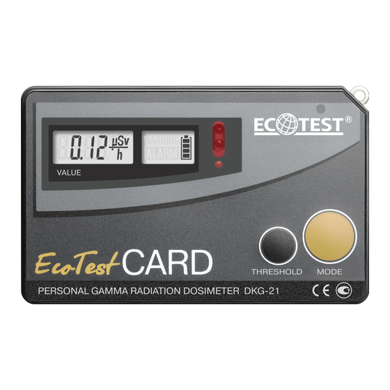
- Page 21 A transparent window, with the dLCD (6) located behind it, is in the left upper corner of the front panel. Two smaller windows for the optical system of the infrared port (7) and the light-emitting diode indicator (8) are located next to this window.
- Page 22 The components of the device and the printed circuit board are fastened with five screws. The storage battery (12) is inserted into the battery compartment (13), and connected to the circuit by two spring contacts. The inscriptions that specify polarity of the storage battery insertion are applied at the bottom of the battery compartment.
- Page 23 Buttons MODE and THRESHOLD serve to switch on the dosimeter, set the required mode of operation and program threshold levels of audible alarm. CCS is implemented on an application-specific integrated circuit and provides SB charging and indication of charging process and its completion. Additional radioelements protect CCS from power surges and impulse noise.
- Page 24 AVF is built under the waiting multivibrator circuit with transformer voltage multiplication and subsequent asymmetric diode capacitive voltage multiplier, and is used to form the anode voltage, required for operation of the ionizing radiation detector. DCC is realized on the basis of a number of switching and normalizing elements and is used for normalization of the detector’s "dead time".
- Page 25 dLCD is a sign-character liquid crystal display with LED illumination, and is used to visualize measurement results in different modes of operation of the dosimeter. 3.4.3.2 The dosimeter operates as follows. If switched off, the dosimeter’s circuit is in a micro-consuming mode of operation (µA units), the circuit is powered from LVS.
- Page 26 Using the DCC the processor normalizes the duration of "dead time" at each actuation of the counter with high accuracy, which allows considering it in the applied algorithm of pulse flow processing for linearization of counting response and expansion of the dynamic range of the counter. Choose the respective operating modes of the dosimeter by successive short presses of the MODE button.
- Page 27 3.5 Labeling and sealing 3.5.1 Labeling complies with Design Documentation ВІСТ.412118.031-02.02. 3.5.2 The front panel of the dosimeter is inscribed with the: - full name of the dosimeter; - trademark of the manufacturer; - a sign of a legally regulated Measurement Instrument in accordance with the Technical Regulations.
- Page 28 3.5.4 Labeling quality complies with the recommendations of GOST 26828-86 and is maintained during service life under all conditions and modes, except for labeling done on the individual package. 3.5.5 The dosimeter accepted by the Quality Control Department (QCD) and prepared for packing is sealed with a special film seal, covering the screw heads, which fasten together...
-
Page 29: Proper Use Of The Dosimeter
- handling marks (No.1 "Fragile-Handle with care", No.3 "Keep dry", No.11 "Top"). 3.5.7 Transport container with the packed dosimeter shall be sealed by the QCD representative of the manufacturer in accordance with GOST 18680-73. 3.6 Packing 3.6.1 Packing is performed in accordance with the requirements specified in Design Documentation ВІСТ.412118.031-02.02. - Page 30 4.2 Preparation of the dosimeter for operation 4.2.1 The scope and order of external examination 4.2.1.1 Before using the dosimeter, unpack it and check if the delivery kit is complete. Examine for mechanical damages. 4.2.2 Rules and order of examination for operational readiness 4.2.2.1 Examine the control buttons before switching the dosimeter on.
- Page 31 Charging should be carried out at ambient temperature ranging from 0 to 45 The lithium-ion battery of the dosimeter has no memory effect, so you can charge the battery regardless of its state of discharge. 4.2.3.2 To charge the storage battery, unpack the charger and connect it to the industrial network of 100-240 V, 50-60 Hz.
- Page 32 - open the battery compartment and insert the storage battery of LIR2450 type observing the polarity. The dosimeter should turn on and conduct a 2- second self-testing of the dLCD and the loudspeaker. During the self-test, the dLCD illumination should be switched on and all its segments should be highlighted, a single-tone sound signal should be generated, and a red LED should be illuminated.
- Page 33 4.2.4.4 Press shortly the MODE button and make sure the dosimeter has entered the mode of the alarm clock setting, which is indicated by a non- blinking colon between the two pairs of digits on the dLCD. 4.2.4.5 Switch off the dosimeter by holding the MODE button pressed for 4 s.
- Page 34 Table 4.1 - Possible troubles and troubleshooting Trouble Probable cause Solution 1 The dosimeter does 1 Storage battery is low 1 Charge the storage not switch on after the 2 Poor contact between the battery MODE button is storage battery and the 2 Restore the contact pressed battery compartment...
- Page 35 Table 4.1 (continued) Trouble Probable cause Solution 3 The “Err1” symbol is Failure of the anode Send the dosimeter displayed on the dLCD voltage former or the for repair to the during operation of the ionizing radiation manufacturer dosimeter detector 4 The storage battery of 1 Disconnect and 1 Poor contact between...
- Page 36 4.3 Use of the dosimeter 4.3.1 Safety measures during use 4.3.1.1 The dosimeter meets the safety requirements in accordance with DSTU EN 61010-1:2014. 4.3.1.2 The dosimeter contains electric circuits of voltage up to 500 V; dismantle the dosimeter when the power supply is switched off. 4.3.1.3 The dosimeter’s design excludes any electric voltages exceeding 42 V on the outside of the dosimeter.
- Page 37 Note. If the dosimeter is contaminated by any liquid or dry radionuclides and it is impossible to completely decontaminate the device, the dosimeter should be buried as solid radioactive waste. 4.3.2 Operating modes of the dosimeter 4.3.2.1 The dosimeter operates within the following modes: - switching the dosimeter on/off;...
- Page 38 4.3.3 Operation procedure of the dosimeter 4.3.3.1 Switching the dosimeter on/off Press shortly the MODE button to switch the dosimeter on. When switched on the dosimeter is testing the dLCD and the loudspeaker for 2 s. All dLCD segments are highlighted and a one-tone sound signal is generated.
- Page 39 The blinking digits on the dLCD indicate that the infrared port is active. As soon as data exchange with the PC is finished, the dosimeter starts accumulating the dose history with the preset interval. Otherwise, the dosimeter starts operating in a stand-alone mode with integral dose accumulation without dose history accumulation.
- Page 40 4.3.3.3 Measurement of DER After dLCD self-testing is finished, the dosimeter enters the mode of DER measurement. This mode can be entered from any other operating mode by shortly pressing the MODE button. The units of measurement are expressed in µSv/h. The process of DER measurement accumulation and averaging will start after the dosimeter is switched on.
- Page 41 Hence, the measurement result can be used only for rough evaluation of DER. The steady point informs that the statistical error of the DER measurement result is within the permissible range. The main direction of the dosimeter during DER measurement is the direction perpendicular to the front (rear) panel of the dosimeter.
- Page 42 4.3.3.4 Programming of audio and light DER alarm threshold level Audio and light alarm threshold levels of DER are programmed in the mode of DER measurement. Press the THRESHOLD button and hold it down for about 5 s until the low-order digit starts blinking on the dLCD to start programming.
- Page 43 The threshold level is stored in the nonvolatile memory of the dosimeter. Switching the dosimeter on and off and replacing its battery does not change the threshold level. Press the THRESHOLD button and hold it down not more than 2 s after a threshold level value and the ALARM transparency appear to check the value of the DER threshold level.
- Page 44 4.3.3.5 Indication of DE measured value Press shortly the MODE button to enter the mode of DE measurement indication. This mode follows the mode of DER measurement. The “mSv” symbol that appears on the dLCD indicates you have entered the appropriate mode.
- Page 45 Set an appropriate value of the low-order digit by successively pressing and releasing the THRESHOLD button. Press shortly the MODE button to proceed to programming of another digit, the latter will start blinking. Set the required value of the digit by pressing and releasing the THRESHOLD button.
- Page 46 Hold the THRESHOLD button down for more than 4 s to set the threshold value to zero. The low-order digit will start blinking at that indicating that a new threshold level value can be programmed. A blinking red light-emitting diode and the ALARM transparency, as well as a two-tone audio alarm indicate that the programmed DE threshold level has been exceeded.
- Page 47 4.3.3.7 Setting the measure DE value to zero Setting DE measured value to zero is performed in the mode of DE measurement indication. To reset the DE, simultaneously press and hold MODE and THRESHOLD buttons until “CLr” symbols appear on the dLCD of the dosimeter.
- Page 48 4.3.3.8 Indication and correction of real time Press shortly the MODE button to enter this mode from any other mode of operation. This mode follows the mode of DE measurement indication. It is indicated by a one-second blinking “:” symbol between the two pairs of the dLCD digits.
- Page 49 Each pressing will change the value per unit. Press shortly the MODE button to correct the value of hours. The two digits to the left from the “:” symbol start blinking at that. The hour value correction is performed likewise. Press shortly the MODE button once again to exit the mode of real time correction.
- Page 50 Press the THRESHOLD button and hold it down until the two digits to the right from the “:” symbol start blinking to correct the alarm clock settings. Release the button afterwards. Set the proper values of units and tens of minutes by further pressing and holding the THRESHOLD button.
- Page 51 Press shortly the THRESHOLD button to switch the alarm clock off. The "WARNING" transparency should extinct. Memorize the alarm clock settings by further short pressing of the MODE button. This is evidenced by a four-time blinking of the dLCD of the dosimeter. If the alarm is on, the "WARNING"...
- Page 52 4.3.3.10 Storage battery status control When switched on, the dosimeter continuously controls and displays a storage battery status on the dLCD. It is indicated by a battery symbol consisting of four segments. When the battery is fully charged, all segments of the battery symbol are highlighted.
-
Page 53: Technical Maintenance
5 TECHNICAL MAINTENANCE 5.1 Technical maintenance of the dosimeter 5.1.1 General instructions The list of operations performed during technical maintenance (hereinafter called TM) of the dosimeter, the order and the peculiarities of operational phases are presented in Table 5.1. Table 5.1 - List of operations during technical maintenance TM type during During... - Page 54 5.1.2 Safety measures 5.1.2.1 TM safety measures fully comply with safety measures stated in item 4.3.1 of the present OM. 5.1.3 Maintenance procedure of the dosimeter 5.1.3.1 External examination External examination of the dosimeter should be performed in the following order: - check the technical condition of surface, inspect for integrity of seals, absence of scratches, traces of corrosion, surface damage of the dosimeter;...
- Page 55 5.1.3.3.2 Procedure for pre-repair fault detection and rejection The need to transfer the dosimeter for repair and the type of repair is determined by the following criteria: - for mid-life repair: a) deviation of parameters from control values during periodic verification of the dosimeter;...
- Page 56 5.1.3.4 Power supply switch off Storage battery should be removed before the long-term storage of the dosimeter. Do this as follows: - fully charge the storage battery; - switch the dosimeter off; - open the lid of the battery compartment; - remove the storage battery;...
- Page 57 5.2 Verification 5.2.1 The DKG-21 dosimeter should be verified during use and after repair. IMPORTANT! Devices used in the automated dosimetry control system and are handed over for verification must be unlocked as regards the prohibition of access to all their modes of operation (indication of individual dose equivalent, individual dose equivalent rate, programming of alarms triggering by threshold levels of individual dose equivalent and its rate).
- Page 58 Table 5.2 (continued) Verification Operation name technique No. Calculation of main relative permissible error limit of DER 5.2.7.3, measurement in the DER range of 1.0 μSv/h to 1.0 Sv/h 5.2.7.4 Calculation of main relative permissible error limit of DE 5.2.7.3, measurement in the DER range of 1.0 μSv/h to 1.0 Sv/h in 5.2.7.5 the DE range of 0.01 to 9999 mSv...
- Page 59 Table 5.3 (continued) Name Regulatory Document or Main Technical Specifications Dimensions: 30 × 30 × 15 cm; PMMA walls Phantom (polymethylmethacrylate, front wall thickness – 2.5 mm, other walls thickness – 10 mm); phantom is filled with distilled water МВ-4М Л82.844.000 ПС.
- Page 60 5.2.5 Verification should be performed in accordance with safety measures presented in item 4.3.1 of the OM. 5.2.6 Verification conditions Verification should be performed under the following conditions: - ambient air temperature range within (20±5) °C; - relative air humidity from 30 to 80 %; - atmospheric pressure from 86 kPa to 106.7 kPa;...
- Page 61 - the delivery kit should be completed as stated in Table 3.1; - labeling should be accurate; - QCD seals should not be violated; - the dosimeter should be free from mechanical damage that may affect its performance. 5.2.7.1.2 If the requirements in 5.2.7.1.1 are satisfied, proceed to the next verification operation.
- Page 62 5.2.7.2.1.2 Even if a single operation stated in 4.2.4 cannot be performed, the dosimeter should not be verified and should be sent for repair. 5.2.7.3 DER and DE measurement should be performed on the phantom with 30x30x15 cm dimensions, with PMMA walls (polymethylmethacrylate, front wall thickness - 2.5 mm, other walls...
- Page 63 H ) in УПГД-3Б Take five measurements of background DER ( рфі with 10 s interval in thirty minutes after the dosimeter is switched on. Calculate the average DER value in μSv/h by the formula рфі (5.1) pф...
- Page 64 Note. The distance between the mechanical center of the source and the mechanical center of the dosimeter’s detector is considered to be the distance between the mechanical center of the source and the plane, which is perpendicular to the direction of gamma-quanta beam spreading, and passes through the mechanical center of the dosimeter in this plane.
- Page 65 5.2.7.4.7 Maximum value of all received errors is the limit of main relative permissible error of DER measurement. 5.2.7.4.8 If the main relative permissible error limit of DER measurement at 0.95 confidence probability does not exceed: - 20 % in the DER range of 1.0 to 10 μSv/h; - 15 % in the DER range of 10 μSv/h to 1.0 Sv/h, proceed to the next verification operation.
- Page 66 5.2.7.5.2 Fix the dosimeter on the phantom as stated in 5.2.7.3 in the УПГД-3Б carriage so that the mechanical center of the УПГД-3Б collimator coincides with the mechanical center of the dosimeter’s detector. 5.2.7.5.3 Prepare the dosimeter for DE measurement and place the УПГД-3Б...
- Page 67 − (5.3) - DE of УПГД-3Б equipment; where - main relative permissible error limit of DE of УПГД-3Б equipment; ...
- Page 68 5.2.7.5.6 The result of the dosimeter verification is considered positive if the main relative permissible error limit of DE measurement at 0.95 confidence probability does not exceed 15 %. 5.2.7.5.7 If the limit of main relative permissible error of DE measurement does not meet the requirements stated in 5.2.7.5.6, the dosimeter cannot be verified and should be sent for repair.
-
Page 69: Storage
6 STORAGE 6.1 The dosimeters should be stored packed under conditions according to category 1 (Л) GOST 15150-69, safe from mechanical damage in dry, ventilated and clean storehouses at the ambient temperature from +5 to +40 °C and relative humidity up to 80 % at + 25 °C temperature. The storehouse should be free of dust, vapors of acids, alkali and gas that may cause corrosion. - Page 70 - by railway transport – in a clean box car; - by air transport – in pressurized compartments; - by water transport – in a dry hold; - by motor transport – in a closed car. 7.3 The dosimeters in shipping container should be placed and fixed in the vehicle to ensure their stable position throughout the way without displacement, and to avoid shocks.
-
Page 71: Disposal
8 DISPOSAL Disposal of the dosimeter is performed in compliance with DSTU 4462.3.01, DSTU 4462.3.02, the Laws of Ukraine "On Environmental Protection" and "On Waste, i.e. metals are recycled or melted, and plastic parts are dumped. Note. If the dosimeter is soiled by liquids or dry radionuclides, and it is impossible to completely decontaminate it, it should be buried as solid radioactive waste at the enterprises of UkrDO Radon, or other applicable facilities. -
Page 72: Warranty
9 WARRANTY 9.1 The manufacturer guarantees the conformity of the dosimeter to the technical requirements ТУ У 33.2-22362867-010:2007 provided that the customer observes the guidelines for its use, shipping and storage presented in the operating manual ВІСТ.412118.031-02.02 НЕ. 9.2 The warranty period of the dosimeter shall terminate and be of no further effect in 24 months after the date of putting it into operation or after the warranty period of storage terminates according to GOST 27451-87. - Page 73 9.5 Warranty is invalid in case of use, shipping and storage violations, any mechanical damages, or if the warranty seals are violated. In this case the repair is performed at the user’s expense. 9.6 After the warranty period terminates, the repair of the dosimeter is performed under separate contracts.
-
Page 74: Packing Certificate
10 PACKING CERTIFICATE DKG-21 personal gamma radiation dosimeter ВІСТ.412118.031-02.02 type with ________________________________ serial number is packed by the Private Enterprise “SPPE “Sparing-Vist Center” in accordance with the requirements specified in ТУ У 33.2- 22362867-010:2007. _____________________ ______________________________ (position) (signature / print full name) -
Page 75: Certificate Of Acceptance
11 CERTIFICATE OF ACCEPTANCE DKG-21 personal gamma radiation dosimeter ВІСТ.412118.031-02.02 type with _________________________serial number is manufactured to meet the technical requirements specified in ТУ У 33.2-22362867-010:2007, and is accepted for use. QCD head _______________________ (signature / print full name) Stamp here... -
Page 76: Performance Records Of The Device
12 PERFORMANCE RECORDS OF THE DEVICE 12.1 Performance records of the dosimeter are provided in Table 12.1. Table 12.1 Operation duration performed Date Purpose Duration Note Start operation... - Page 77 13 CLAIMS 13.1 In case of failure or troubles during the warranty period of the dosimeter, the user should draw up a statement of claim and send the dosimeter to the producer-enterprise. 13.2 All claims are registered in the Table 13.1. Table 13.1 Date of Claim summary...
- Page 78 14 ACCEPTANCE AND WARRANTY The DKG-21 personal gamma radiation dosimeter of ВІСТ.412118.031- 02.02 type with ___________________________________ serial number, repair type ______________________________________ made by the manufacturer PE “SPPE “Sparing-Vist Center” is accepted in accordance with the requirements specified in ТУ У 33.2-22362867- 010:2007 and acknowledged fit for use.
- Page 79 APPENDIX А Anisotropy Cs-137 of DKG-21 СО-60 Ам-241 (vertical plane) Ам -241 Co- 60 -100 Cs - 137 П Figure А.1...
- Page 80 Anisotropy Cs-137 of the dosimeter СО-60 Ам-241 DKG - 21 (horizontal plane) Ам -241 -100 Cs - 137 Co- 60 П Figure А.2...
- Page 81 APPENDIX B Figure B.1 – Front view of the dosimeter...
- Page 82 Figure B.2 - Rear view of the dosimeter...
- Page 83 Figure B.3 – Connecting the charger...
- Page 84 APPENDIX C Figure C.1 - Block diagram of the dosimeter...
- Page 85 APPENDIX D PUTTING IN PROLONGED STORAGE AND REMOVAL FROM STORAGE Date, position, Date of Date of Name of the enterprise in and signature putting in removal charge of putting the unit in Method of the prolonged from prolonged storage or responsible storage storage...
- Page 86 APPENDIX Е STORAGE Date Position, name and Storage conditions signature of the of placing in of removing responsible official storage from storage...
- Page 87 APPENDIX F TROUBLE RECORD DURING USЕ Date Cause of Position, name Type trouble, and signature of (external time of number of Action taken the person manifestat trouble. operation and claim note responsible for ion) of Operatin hours of the solving the trouble g mode failed element...
- Page 88 APPENDIX G VERIFICATION OF KEY SPECIFICATIONS Verified specification Date of measurement Value year 20 year 20 according Measured by Measured by Name Actual value (position, Actual value (position, specifica- signature) signature) tion 1 Main relative error limit of the dosimeter of DER measurement with confidence probability of 0.95, % in the DER...
- Page 89 APPENDIX G Date of measurement year 20 year 20 year 20 Measured by Measured by Measured by Actual value (position, Actual value (position, Actual value (position, signature) signature) signature)
- Page 90 APPENDIX G VERIFICATION OF KEY SPECIFICATIONS Verified specification Date of measurement year 20 year 20 Value Measured by Measured by Name according to Actual value (position, Actual value (position, specification signature) signature) 2 Main relative error limit of the dosimeter of DE measurement in the DER range from 1.0 μSv/h to1 Sv/h...
- Page 91 APPENDIX G Date of measurement year 20 year 20 year 20 Measured by Measured by Measured by Actual value (position, Actual value (position, Actual value (position, signature) signature) signature)
- Page 92 APPENDIX H REPAIR Date Name and symbol of the Reason for Name of the repair admission withdra- component part repair body to repair wal from repair...
- Page 93 APPENDIX H REPAIR Position, name and signature of Number of Type of repair the responsible official hours (middle-life, Name of repair work worked who performed accepted after major) before repair repair repair...
- Page 94 APPENDIX I VERIFICATION AND INSPECTION RESULTS Verification or Verification or Position, name and Date Note inspection type inspection result signature of the inspector...
- Page 95 LIST OF ABBREVIAITONS ASPIC - automated system of individual dosimetry control IRPA - infrared port adapter - storage battery - loudspeaker - detector of ionizing radiation - individual dose equivalent - nonvolatile memory - linear voltage stabilizer - operating manual - individual dose equivalent rate...
- Page 96 - software - personal computer IrPC - infrared port circuit - charging control circuit - voltage stabilization circuit - detector control circuit DPCC - digital processing and control circuit - anode voltage former dLCD - digital liquid crystal display...
Need help?
Do you have a question about the DKG-21 and is the answer not in the manual?
Questions and answers