Advertisement
Quick Links
Advertisement

Related Manuals for ECOTEST BDBG-09S


Summary of Contents for ECOTEST BDBG-09S
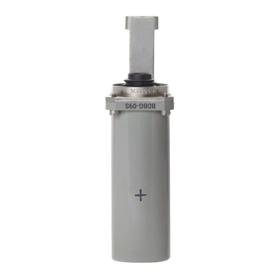
- Page 1 BDBG-09S DETECTING UNIT OF GAMMA RADIATION Operating manual BICT.418266.032-02 НЕ...
-
Page 3: Table Of Contents
CONTENTS 1 DESCRIPTION AND OPERATION ....................3 2 PROPER USE ........................... 8 3 MAINTENANCE ........................... 11 4 REPAIR ............................17 5 STORAGE AND PUTTING IN PROLONGED STORAGE............17 6 SHIPPING ............................17 7 DISPOSAL............................17 APPENDIX А ............................ 18 APPENDIX B ............................ 26 APPENDIX C ............................ -
Page 4: Description And Operation
This operating manual (the OM) is intended to inform the user about principles of operation, rules of application, maintenance, storage and shipping of the BDBG-09S detecting unit of gamma radiation. The OM contains the following abbreviations: H - ambient dose equivalent rate of gamma radiation;... - Page 5 Table 1.1 (continued) Standardized Unit of value according Name measurement to the specifications 7 Operating supply voltage range of the detecting 7 - 32 unit from external regulated power supply 8 Consumption current of the detecting unit for overall range of measured gamma radiation DER, not more than 9 Setup time of operating mode and measurement time of the detecting unit, not more than...
- Page 6 1.3 Delivery kit of the detecting unit The delivery kit of the detecting unit consists of units and maintenance documentation, given below. 1.3.1 ВІСТ.418266.023-02 BDBG-09S detecting unit ......1 pc. 1.3.2 ВІСТ.745265.001Corbel ..............1 pc. 1.3.3 ВІСТ.418266.032-02 НЕ Operating manual ........1 copy.
- Page 7 Alternatively, the detecting unit can be fastened to the surface where it will be directly installed is shown in Figure 1 (b). The Figure 1 (b) shows that the barrel of the detecting unit with a reference point (5), indicating the direction towards the radioactive source, is attached with its base (2) to the surface using a plank (3).
- Page 8 1.5 Measuring instruments, tools and equipment 1.5.1 A list of measuring instruments, tools and equipment necessary for control, setting and current repair of the detecting unit is presented in the Table 1.2. Table 1.2 – List of measuring instruments, tools and equipment Standardized document or main technical Name requirements...
-
Page 9: Proper Use
1.6.2 Sealing of the device is performed by the producer enterprise. 1.6.3 Removal of seals and repeated sealing is performed by the organization in charge of repair of the units. 1.6.4 Labeling of the shipping container contains main (consignee and destination), additional (consigner of goods and origin), and informational (gross and net weight in kg) letterings, as well as handling marks No.1 “Fragile –... - Page 10 2.2.2.2 Before using the detecting unit that was on temporary closing-down, re-activate it and check its operability. 2.2.2.3 Register the re-activation and putting the detecting unit in operation in the logbook. 2.2.3 Guidelines on switching on and testing the detecting unit with description of testing procedure of the detecting unit in operation 2.2.3.1 Prepare the PC-based data display system for operation.
- Page 11 Table 2.1 (continued) Trouble Probable cause Troubleshooting 2 Information evidence of the 2 Failure of the high 2 Send the detecting unit for high sensitivity detector failure sensitivity detector, which is repair to the repair services or (D0 bit is set in the byte of the a part of the detecting unit to the producer enterprise self-testing results of the...
-
Page 12: Maintenance
3 MAINTENANCE 3.1 Technical maintenance of the detecting unit 3.1.1 General instructions The list of operations during technical maintenance (hereinafter the TM) of the detecting unit, order and peculiarities of operational phases are given in the Table 3.1. Table 3.1 – List of operations during maintenance Maintenance type during during... - Page 13 To deactivate, wipe thoroughly the contaminated areas with a cloth moistened with decontamination solution, then with a cloth moistened with warm water and wipe dry. Notes 1 Before deactivating the detecting unit, put on cotton gloves and rubber (surgical) gloves, observing safety requirements for operation with chemical solutions.
- Page 14 Table 3.2 – Verification operations Verification procedure Operation name 1 External examination 3.2. 4.1 2 Testing 3.2. 4.2 3 Calculation of main relative permissible error limits of gamma 3.2.4.3 radiation DЕR measurement 3.2.2 Testing facilities The following measuring instruments and equipment should be used during testing: - УПГД-3В...
- Page 15 3.2.4.2 Testing The detecting unit should be tested according to 2.2.3. 3.2.4.3 Calculation of main relative error at gamma radiation DER measurement 3.2.4.3.1 Prepare the УПГД-3В standard equipment of gamma radiation for operation. 3.2.4.3.2 Fix the detecting unit in the УПГД-3В carriage holder, so that the mechanical center of gamma quanta beam coincides with the center of detectors.
- Page 16 3.2.4.3.11 Calculate the limit of relative residual bias of measurement results by the formula: − (3.5) H where - is a limit of main relative permissible error of gamma radiation DER of УПГД-3В.
- Page 17 3.2.4.3.17 Perform operations 3.2.4.3.16 of the OM for gamma radiation DER from Cs source H = (800100) µSv/h. with the value of 3.2.4.3.18 Perform operations 3.2.4.3.16 of the OM for gamma radiation DER from Cs source H with the value of = (80.1) mSv/h.
-
Page 18: Repair
PE “SPPE “Sparing-Vist Center” Tel.: (+38032) 242 15 15, fax: (+38032) 242 20 15 E-mail: sales@ecotest.ua. 5 STORAGE AND PUTTING IN PROLONGED STORAGE 5.1 Before putting in operation, the detecting unit should be stored in the packing of the producer enterprise in storehouses under special conditions. - Page 19 3 The technological software can operate on the IBM-compatible personal computer (PC) with installed Windows 98 and further versions of the operating system. 4 Connection of the BDBG-09S detecting unit to the PC, and power supply of the BDBG-09S is done with the help of the USB <--> RS-485 interface adapter.
- Page 20 If the new USB Serial Port does not appear, repeat the steps above and restart the PC. You can download the latest version of the drivers from www.ftdichip.com. For proper functioning of the bdbg_s.exe program set the minimum value of 1mS in the Latency Timer option of the USB serial port.
- Page 21 - click Advanced - change the value of Latency Timer for 1 mS; - finish input by clicking ОК.
- Page 22 (*.txt) (for instance, Notepad). The example of measurement results, saved with the help of the bdbg_s.exe program, is given in the Appendix C. The Light version indicator is used for operation with the BDBG-09S detecting unit version for everyday use without the low sensitivity detector.
- Page 23 Next, select the Base mode tab (Figure A.2). Figure А.2 – Bdbg_s.exe program window with the active Base mode tab The following grouped data will be displayed on the monitor: - Serial # – indicates a serial number of the detecting unit. - MEASURED DOSE RATE –...
- Page 24 Caution! After clicking the Change button, values from the input fields New block address and New delay factor are simultaneously sent to the detecting unit. Therefore, before clicking Change make sure all values of the input fields are correct. If the detecting unit is operated using the v1.2 protocol, the Current delay factor and the New delay factor fields are unavailable and data is not transferred to the detecting unit.
- Page 25 Start date – shows a start date of the spectrum accumulation. Temperature – shows temperature results received from the detecting unit. There is a group below, displaying a spectrum accumulated by the SDUGR of BDBG-09S. The spectrum channels are plotted horizontally whereas the values corresponding to the number of pulses for this channel are distributed vertically.
- Page 26 To return to a previous zoom level, make selection of any fragment of the spectrum from left to right so that the mouse cursor be positioned beyond the boundaries of a field, displaying the spectrum, and then release a button. In the bottom right corner, there are two buttons to start a new spectrum accumulation (Restart) and stop/continue it (Pause/Continue).
- Page 27 APPENDIX B COMMUNICATIONS PROTOCOL OF THE DATA DISPLAY SYSTEM AND THE DETECTING UNIT B.1 Data frames exchange between the detecting unit and the data display system is done via the RS-485 interface in a half-duplex mode. Exchange parameters: - rate: 19200 bps; - data word length: 8 bit;...
- Page 28 “DER query” frame format –the data display system to the detecting unit Byte 55h – start-of-frame character Byte AAh D7...D4 – “DER query” frame code А3 А2 А1 А0 D3...D0 – detecting unit address * * - 0Fh address – broadcast address. All detecting units respond to the query with such address. “Current DER”...
- Page 29 “Temperature query” frame format – the data display system to the detecting unit (for the detecting units with embedded temperature detector) Byte 55h – start-of-frame character Byte AAh D7…D4 – “Temperature query” frame code А3 А2 А1 А0 D3…D0 – detecting unit address * * - 0Fh address –...
- Page 30 “Serial # query” frame format – the data display system to the detecting unit Byte 55h – start-of-frame character Byte AAh D7…D4 – “Serial # query” frame code А3 А2 А1 А0 D3…D0 – detecting unit address * * - 0Fh address – broadcast address. All detecting units respond to the query with such address. “Serial #”...
- Page 31 B.3.2 Communications protocol with the 8-digit field address (v1.3). To receive the measured value of DER from the detecting unit, the data display system should transmit the “DER1 query” frame to the detecting unit. The detecting unit will respond in 5 ms to 15 ms with the “Current DER1”...
- Page 32 To receive gamma radiation spectrum from the detecting unit there are two frames «Expert» and «Expert1». Frame «Expert». The information display system should transmit the following sequence BLOCK in "Expert" frame: 1. Frame "Expert" BLOCK = 9 in BDBG (query for the new spectrum accumulation) 2.
- Page 33 “DER1 query” frame format –the data display system to the detecting unit Byte 55h - start-of-frame character Byte AAh D7…D4–protocol v1.3 character address D7…D0– detecting unit address * D7…D0–“DER1 query” frame code control arithmetical checksum with a carry * - 0FFh address – broadcast address. All detecting units respond to the query with such address. “Current DER1”...
- Page 34 "Intensity query for 100msec" frame format - data display system to detecting unit: D7 D6 D5 D4 D3 D2 D1 D0 1 Byte 55h - start-of-frame character Byte AAh 0 D7…D4– protocol v1.3 character address D7…D0– detecting unit’s address* 0 D7…D0–“Intensity for 100msec” frame code control arithmetical checksum with a carry * - 0FFh address –...
- Page 35 “Temperature1 query” frame format – the data display system to the detecting unit (for the detecting units with embedded temperature detector) Byte 55h – start-of-frame character Byte AAh D7…D4– protocol v1.3 character address D7…D0– detecting unit address* D7…D0–“Temperature1 query” frame code control arithmetical checksum with a carry * - 0FFh address –...
- Page 36 “Serial #_1 query” frame format – the data display system to the detecting unit Byte 55h – start-of-frame character Byte AAh D7…D4– protocol v1.3 character address D7…D0– detecting unit address* D7…D0–“Serial#_1 query” frame code control arithmetical checksum with a carry * - 0FFh address –...
- Page 37 “Address1 change” frame format – the data display system to the detecting unit Byte 55h – start-of-frame character Byte AAh D7…D4– protocol v1.3 character D7…D0– current address of the detecting current address unit D7…D0–“Address1 change” frame code new address D7…D0– new address of the detecting unit D7…D0–...
- Page 38 “Expert” frame format – data display system to the detecting unit 0x0B – Expert (spectrum, DER, temperature, error); 0x0E – Firmware; Byte 55h - start-of-frame character Byte AAh D7…D4– protocol v1.3 character address D7…D0– address of the detecting unit* Експерт D7…D0–...
- Page 39 “Expert” frame format – data display system to the detecting unit Byte 55h - start-of-frame character Byte AAh D7…D4– protocol v1.3 character address D7…D0– address of the detecting unit* D7…D0– “ ” frame code Expert Number of spectrum block BLOCK byte The structure of the following data is defined by the spectrum block number BLOCK.
- Page 40 D7=1- failure of temperature detector Low byte Pulses per second (integrated) High byte Byte Model of the device 0хCC – BDBG-09S Serial №_0 (low byte) Serial №_1 Serial No. of the detecting unit Serial №_2 Serial №_3 (high byte)
- Page 41 “Expert1” frame format –data display system to detecting unit 0x8B – Expert1 (spectrum, DER, temperature, error) D7 D6 D5 D4 D3 D2 D1 D0 1 Byte 55h - start-of-frame character Byte AAh D7…D4–protocol v1.3 character address D7...D0 – detecting unit’s address D7…D0–“Expert1”...
- Page 42 D7=0- normal operation of heat sensor D7=1-failure of heat sensor Low byte Pulses per second (integrated) High byte Byte Device model. 0хDD – BDBG-09S Serial #_0 (Low byte) Serial #_1 Serial # of the detecting unit Serial #_2 Serial #_3 (High byte)
- Page 43 D7…D0– address of the detecting unit* D7…D0– “Firmware” frame code Year Byte Month Byte Release version Byte Debug version Byte Device model. 0хCC – BDBG-09S Byte Reserved byte Byte Byte Reserved byte Reserved byte Byte Reserved byte Byte Reserved byte...
- Page 44 B.4 Checksum for data communications using both v1.2 protocol, and v1.3 protocol is calculated according to Figure B.1. byte arithmetical summation checksum partial result carry arithmetical summation carry checksum Figure B.1 – Checksum calculation algorithm B.5 CA6GS 932326-100 HIRSCHMANN interface connection serves to connect the data display system to the detecting unit.
- Page 45 APPENDIX C EXAMPLE OF MEASUREMENT RESULTS SAVED WITH THE HELP OF BDBG_S.EXE PROGRAM ---------------------------------------------------------------------------------------------------- Date Time Max. stat. error Tests results Temperature ---------------------------------------------------------------------------------------------------- BDBG-09S/15S-09/15S-23 #1800020 Response delay factor to broadcast query:1 22.10.2018 11:29:00 0.07 µSv/h 22.10.2018 11:29:06 0.07 µSv/h 23.8 22.10.2018 11:29:11 0.07 µSv/h...
- Page 46 UNIT TO DATA DISPLAY SYSTEM To provide stable operation of the BDBG-09S detecting unit, and stable data communications between the BDBG-09S detecting unit and the data display system, you should use the cable with the following parameters: - number of twisted pairs: not less than 2 (pairs not in use should be connected to minus of power supply from the side, where power is supplied to the cable);...
Need help?
Do you have a question about the BDBG-09S and is the answer not in the manual?
Questions and answers