Table of Contents
Advertisement
Quick Links
Advertisement
Table of Contents

Related Manuals for ECOTEST MKS-05 TERRA


Summary of Contents for ECOTEST MKS-05 TERRA
- Page 1 MKS-05 “TERRA” DOSIMETER-RADIOMETER OPERATING MANUAL ВІСТ.412129.006-04 НЕ...
-
Page 2: Table Of Contents
CONTENTS 1 DESCRIPTION AND OPERATION OF THE DOSIMETER..........4 1.1 Purpose of use.......................4 1.2 Technical specifications..................5 1.3 Delivery kit......................14 1.4 Design and theory of operation ................15 1.5 Labeling and sealing....................18 1.6 Packing.......................18 2 PROPER USE OF THE DOSIMETER.................19 2.1 Operating limitations...................19 2.2 Preparation of the dosimeter for operation............20 2.3 Use of the dosimeter....................25 3 TECHNICAL MAINTЕNANCE..................38... - Page 3 4 CERTIFICATE OF ACCEPTANCE ................56 5 PACKING CERTIFICATE ..................57 6 WARRANTY......................58 7 REPAIR ........................59 8 STORAGE ........................61 9 SHIPPING........................62 10 DISPOSAL........................63 APPENDIX A .......................64 APPENDIX B .......................66...
- Page 4 This operating manual (hereinafter called the OM) is intended to inform the user about the theory of operation and rules of application of the MKS-05 “TERRA” dosimeter- radiometer. The manual contains all information necessary for proper use of the dosimeter and full realization of its technical possibilities.
-
Page 5: Description And Operation Of The Dosimeter
1 DESCRIPTION AND OPERATION OF THE DOSIMETER 1.1 Purpose of use The MKS-05 “TERRA” dosimeter-radiometer (hereinafter called the dosimeter) is designed to measure ambient dose equivalent (DE) and ambient dose equivalent rate (DER) of gamma and X-ray radiation (hereinafter called photon-ionizing radiation), and surface beta- particles flux density. -
Page 6: Technical Specifications
1.2 Technical specifications 1.2.1 Key specifications are presented in Table 1.1. Table 1.1 – Key specifications Unit of Standardized values according to the Name measurement technical specifications Measurement range of photon-ionizing μSv/h 0.1 - 9999 radiation DER Main relative permissible error limit of ... - Page 7 Table 1.1 (continued) Measurement range of photon-ionizing radiation DE 0.001 - 9999 Main relative permissible error limit of photon- ionizing radiation DE measurement with 0.95 ± 15 confidence probability Energy range of registered photon-ionizing radiation 0.05 – 3.00 Energy dependence of the dosimeter readings at photon-ionizing radiation DER and DE measurement ±...
- Page 8 Table 1.1 (continued) Anisotropy of the dosimeter at gamma quantum incidence at solid angle of 30 relative to the main axis of the detector and from the side of the main measurement direction for: - 137 Cs and Co isotopes ±...
- Page 9 Table 1.1 (continued) Measurement range of surface beta- part./(cm ·min) 10 - 10 particles flux density Main relative permissible error limit of 20 beta-particles flux density measurement with 0.95 confidence probability φ is a numeric value of the β...
- Page 10 Table 1.1 (continued) Measurement range of DE accumulation time with measurement resolution of 1 min Absolute permissible error limit at operator’s DE accumulation ± 1 time measurement during 24 hrs Time of the dosimeter operating mode setting, not more than Battery life (AAAx2 of 1280 mA·h capacity) under natural background radiation and switched off display backlight, not more 2000...
- Page 11 Table 1.1 (continued) General operating supply voltage of the dosimeter from two batteries Useful current of the dosimeter at operating supply voltage of 3.0 V under natural background radiation and switched off display backlight, not more than Additional permissible error limit at measurement caused by supply voltage deviation from nominal value in the range of 3.2 to 2.4 V ±...
- Page 12 Table 1.1 (continued) Mean time to failure, not less than 6000 Average life of the dosimeter to the first major overhaul, not 10000 less than Average service life of the dosimeter, not less than year Average shelf life of the dosimeter, not less than year Dimensions, not more than 52x26x120...
- Page 13 1.2.4 Threshold level values of surface beta-particles flux density in the range of 0 to 9999·10 part./(cm ·min) with discreteness of 0.0110 part./(cm ·min) are programmed in the dosimeter. 1.2.5 The dosimeter sends a one-tone audio signal if gamma quantum or beta-particle gets to the detector, and a two-tone audio signal if the programmed DER, DE or surface beta- particles flux density threshold levels have been exceeded.
- Page 14 - temperature from - 20 to + 50 o C; - relative humidity up to (95±3) % at + 35 o C; - atmospheric pressure from 84 to 106.7 kPa. 1.2.9 The dosimeter is resistant to the following external factors: - high frequency sinusoidal vibration in the range of 10 - 55 Hz;...
-
Page 15: Delivery Kit
1.3 Delivery kit 1.3.1 The delivery kit consists of the dosimeter and the maintenance documentation presented in Table 1.2. Table 1.2 - Delivery kit of the dosimeter TYPE Item Quantity Notes MKS-05 “TERRA” BICT.412129.008 1 pc. dosimeter-radiometer Operating manual 1 pc. BICT.412129.006-04 HE BICT.412915.001 Package... -
Page 16: Design And Theory Of Operation
1.4 Design and theory of operation 1.4.1 General information The dosimeter is a mono-block construction with a built-in detector of gamma and beta radiation, a printed-circuit board equipped with a circuit of the anode voltage formation, digital processing, control, and indication, and batteries. Gamma and beta radiation detector transforms radiation into the sequence of voltage pulses;... - Page 17 - measurement of DE accumulation time and real time; - generation and stabilization of the detector’s anode voltage; - operating modes control; - measurement results indication. The power for operation is supplied by two batteries of AAA type. 1.4.2 Design description The dosimeter is designed as a flat square plastic body with rounded corners.
- Page 18 The circuit board (10) is located inside the unit, where all elements of the electric circuit, with an exception of a loudspeaker, are located (5). The loudspeaker is fixed to the upper cover (1) and electrically connected with the circuit board (10) by spring contacts. The latter (10) is screwed to the upper cover (1) of the housing.
-
Page 19: Labeling And Sealing
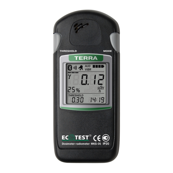
1.5 Labeling and sealing 1.5.1 The upper cover of the dosimeter is inscribed with the name, the symbol of the device, the trademark of the producer, the ingress protection rating of the dosimeter, and the approval pattern of measuring instruments. A factory number and a manufacture date are inscribed on the lower cover. -
Page 20: Proper Use Of The Dosimeter
2 PROPER USE OF THE DOSIMETER 2.1 Operating limitations Operating limitations are presented in Table 2.1. Table 2.1 - Operating limitations Operating limitations Limitation parameters Ambient air temperature from - 25 to + 50 Relative humidity up to 95 % at + 35 C, non-condensing Photon-ionizing radiation influence DER up to 1.0 Sv/h during 5 min... -
Page 21: Preparation Of The Dosimeter For Operation
2.2 Preparation of the dosimeter for operation 2.2.1 Scope and order of external examination 2.2.1.1 Before using the dosimeter, unpack it and check if the delivery kit is complete. Examine for mechanical damages. 2.2.2 Rules and order of examination for operational readiness 2.2.2.1 Examine the control buttons before switching the dosimeter on. - Page 22 2.2.3 Guidelines on switching on and testing the dosimeter 2.2.3.1 Prepare the dosimeter for operation by doing the following: - unpack the dosimeter; - open the battery compartment and insert two batteries of AAA type, observing the polarity. 2.2.3.2 Press shortly the MODE button to switch the dosimeter on. The dosimeter should enter the mode of photon-ionizing radiation DER measurement, which is shown by the blinking light-emitting diode opposite the appropriate mnemonic symbol below the LCD, and by audio signals following the detection of every gamma quantum.
- Page 23 2.2.3.4 Press shortly the MODE button and make sure the dosimeter has entered the mode of surface beta-particles flux density measurement, which is indicated by the blinking light- emitting diode opposite the appropriate mnemonic symbol below the LCD, and by audio signals following the detection of every beta-particle or gamma quantum.
- Page 24 2.2.3.7 Hold the MODE button pressed for six seconds to switch the dosimeter off. 2.2.4 List of possible troubles and troubleshooting 2.2.4.1 The list of possible troubles and troubleshooting is presented in Table 2.2. 2.2.4.2 At failure to eliminate the troubles presented in Table 2.2, or at detection of more complicated troubles, the dosimeter should be sent for repair to the repair services or to the manufacturer.
- Page 25 Table 2.2 - List of possible troubles and troubleshooting Trouble Probable cause Troubleshooting 1 The dosimeter is not 1 The battery is discharged 1 Replace the batteries switched on after the MODE 2 No contact between the 2 Restore the contact button is pressed batteries and the battery between the batteries...
-
Page 26: Use Of The Dosimeter
2.3 Use of the dosimeter 2.3.1 Safety measures during use of the dosimeter The dosimeter contains no external parts exposed to voltages hazardous for life. It is not dangerous for the service personnel, and is environmentally friendly. A special protection jacket is used to prevent accidental contact with conductive parts. Ingress protection rating is IP20. - Page 27 - programming of audio alarm threshold levels of photon-ionizing radiation DE; - surface beta-particles flux density measurement; - programming of audio alarm threshold levels of surface beta-particles flux density; - indication of operator’s DE accumulation time; - indication and correction of real time; - switching audio signaling of registered gamma quanta and beta-particles on/off;...
- Page 28 2.3.3.2 Measurement of photon-ionizing radiation DER The mode of photon-ionizing radiation DER measurement is entered automatically after the dosimeter is switched on. The mode is indicated by the blinking light-emitting diode opposite the appropriate mnemonic symbol below the LCD. The results of measurement will appear on the LCD during the first few seconds, enabling efficient evaluation of radiation level.
- Page 29 Consider the arithmetic mean of five last measurements after the LCD stops blinking as the DER measurement result. Every registered gamma quantum will be followed by an audio signal. Measurement intervals and subranges will be set automatically, depending on the measured radiation intensity.
- Page 30 To start programming, press the THRESHOLD button and hold it pressed (circa six seconds) until the low-order digit starts blinking on the LCD. Set the necessary value of the low-order digit by successive pressing and releasing the THRESHOLD button. Press shortly the MODE button to program the next digit, which will start blinking at that.
- Page 31 When the THRESHOLD button is pressed for more than four seconds, the low-order digit starts blinking, indicating that a new threshold level value can be programmed. A two-tone audio signal indicates that the programmed DER threshold level has been exceeded. Note.
- Page 32 A blinking light-emitting diode opposite the appropriate mnemonic symbol below the LCD indicates that the DE measurement indication mode has been entered. Measurement units are expressed in mSv. A comma after the first left digit will appear on the LCD when the dosimeter is switched on.
- Page 33 The value of the preset threshold level is fixed after all digits are programmed by short pressing of the MODE button. To fix a new value of the threshold level, set all digits on the LCD by pressing the MODE button, even if the values of the high-order digits are not changed.
- Page 34 by the blinking light-emitting diode opposite the appropriate mnemonic symbol below the LCD. Measurement units are expressed in part./(cm ·min). At first measure gamma background (for further automatic subtraction), and then measure surface beta-particles flux density. To do this, wait until the digital LCD stops blinking in the mode of DER measurement (filter cover covers the window of the detector).
- Page 35 2.3.3.7 Programming of audio alarm threshold level of surface beta-particles flux density Programming of audio alarm threshold level of surface beta-particles flux density is performed in the mode of surface beta-particles flux density measurement and indication. To start programming, press the THRESHOLD button and hold it pressed (circa six seconds) until the low-order digit starts blinking on the LCD.
- Page 36 Press and hold the THRESHOLD button to check the value of the fixed threshold level of surface beta-particles flux density. The threshold level value will appear on the digital LCD in two seconds. When the THRESHOLD button is pressed for more than four seconds, the low- order digit starts blinking, indicating that a new threshold level value can be programmed.
- Page 37 It is indicated by blinking of all digits and a non-blinking comma between the two pairs of digits. The digits from the right to the left will indicate the following: the first digit indicates minutes; the second one - tens of minutes; the third one - hours; the fourth one - tens of hours. 2.3.3.9 Indication and correction of real time Press shortly the MODE button to initiate the mode of real time indication.
- Page 38 value of hours. Two digits on the left of comma start blinking at that. The hour value correction is performed likewise. Press shortly the MODE button once again to exit the mode of real time correction. 2.3.3.10 Switching audio signaling of registered gamma quanta and beta-particles on/off Simultaneously press and release the MODE and THRESHOLD buttons to switch audio signaling off.
-
Page 39: Technical Maintеnance
2.3.3.11 Switching display backlight on/off At pressing any button of the dosimeter or changing the operating mode the display backlight is switched on for 5 seconds. Press shortly the THRESHOLD button to switch the dosimeter display backlight on without changing the operating mode. - Page 40 Table 3.1 - List of operations during technical maintenance TM type During During List of operations Periodical long-term Everyday storage (annually) External examination 3.1.3.1 Delivery kit completeness check 3.1.3.2 Operability check 3.1.3.3 Power supply switch off 3.1.3.4 Verification of the dosimeter Notes.
- Page 41 3.1.2 Safety measures Safety measures during TM fully comply with safety measures stated in item 2.3.1 of the present OM. 3.1.3 Maintenance procedure of the dosimeter 3.1.3.1 External examination External examination of the dosimeter should be performed in the following order: a) check the technical condition of surface, inspect for integrity of seals, absence of scratches, traces of corrosion, surface damages of the dosimeter;...
- Page 42 3.1.3.3.2 Order of pre-repair fault detection and rejection Use the following criteria to evaluate the necessity of sending the dosimeter for repair and type of repair: - for mid-life repair: a) deviation of parameters from reference values during the periodical verification of the dosimeter;...
- Page 43 c) serious mechanical damages of the component parts that affect the security access to the dosimeter circuits. 3.1.3.4 Power supply switch off Power supply should be switched off each time the dosimeter is not in use for a long time. Do the following: - switch the dosimeter off;...
-
Page 44: Verification Of The Dosimeter
3.2 Verification of the dosimeter The dosimeters should be tested after manufacture, repair or during maintenance (periodically, at least once a year). 3.2.1 Verification operations During verification, the operations presented in Table 3.2 should be performed. Table 3.2 – Verification operations Verification Name of operation procedure No. - Page 45 3.2.2 Verification facilities The following measuring instruments and equipment should be used for verification: - testing equipment with standard sources of gamma radiation - flat standard sources on a hard pad, containing Sr + Y radionuclides; - low-active gamma radiation source - standard stop-watch.
- Page 46 - relative air humidity from 30 to 80 %; - atmospheric pressure from 86 to 106.7 kPa; - natural background level of gamma radiation not more than 0.30 µSv/h; - power supply voltage of (3.0± 0.2) V. 3.2.4 Verification procedure 3.2.4.1 External examination During external examination the dosimeter should meet the following requirements: - the delivery kit should be completed as stated in item 1.3.1 of the present OM;...
- Page 47 3.2.4.2 Testing Switch the dosimeter on and program zero values of audio alarm threshold levels of each measuring channel. Afterwards switch on the mode of photon-ionizing radiation DER measurement and place the dosimeter near the Cs gamma radiation source. Observe an increase of DER readings on the LCD upon the background level and audio signaling at registration of every gamma-quantum by the detector.
- Page 48 Perform five measurements of external background EDR and register the received readings in the protocol. Place the holder together with the dosimeter in the position, where DER from Cs source is 0.8 µSv/h. Perform five measurements of DER. Register the received readings in the protocol. H ...
- Page 49 Calculate main relative error of measurement in percentage. Place the holder and the dosimeter in the position, where DER from the Cs source is 8.0 µSv/h. Perform five measurements of DER, and register the received readings in the protocol. Calculate the DER value in µSv/h according to the formula (1). Calculate main relative error of measurement in percentage.
- Page 50 Perform five measurements of DER. Register the received readings in the protocol, and calculate the average value of DER and main relative error of measurement in percentage. Place the holder and the dosimeter in the position, where DER from the Cs source is 8·10 µSv/h.
- Page 51 Prepare the verification equipment for operation according to its operating manual. Fix the dosimeter in the holder so that the mechanical center of gamma beam coincides with the center of the detector. Place the holder and the dosimeter in the position, where DER from Cs source is 80 µSv/h.
- Page 52 Place the holder and the dosimeter in the position, where ambient DER from Cs source is 8000 µSv/h. Fix the initial DE value and simultaneously switch on the stop-watch. Register the DE measurement results after 10 minutes (according to the stop-watch) of irradiation, calculate the main relative error of measurement in percentage, and register the values in the protocol.
- Page 53 Measure ambient gamma background with filter-covered window of the detector in the mode of photon-ionizing DER measurement. Gamma background measurement is completed when the LCD stops blinking. Place the dosimeter with the open window above the 4CO source surface, providing surface beta-particles flux density from 50 to 150 part./(cm ·min), so that the work surface of the detector is placed completely over the active surface of the source.
- Page 54 Calculate the average value of surface beta-particles flux density and the main relative error of measurement. Place the dosimeter with the open window above the 4CO source surface, providing surface beta-particles flux density from 50000 to 100000 part./(cm ·min), so that the work surface of the detector is placed completely over the active surface of the source.
- Page 55 where is a numeric value of the measured surface beta-particles flux density in φ β part./(cm ·min). 3.2.4.6 Presentation of verification results 3.2.4.6.1 Positive results of primary or periodic verification are registered as follows: 1) primary verification is registered in the “CERTIFICATE OF ACCEPTANCE” section; 2) periodic verification is registered in the issued Certificate of the established form.
- Page 56 Table 3.3 – Primary verification of main specifications Tested specification Actual value Standardized values according to the Name specifications Main relative error at measurement of H 10 15+2/ , where is a numeric H 10 photon-ionizing radiation dose equivalent value of the measured DER in µSv/h rate, with 0.95 confidence probability, % Main relative error at measurement of...
-
Page 57: Certificate Of Acceptance
4 CERTIFICATE OF ACCEPTANCE The MKS-05 “TERRA” dosimeter-radiometer of BICT.412129.008 type with _____________________________ serial number meets the ТУ У 33.2-22362867-006-2001 BICT.412129.006 ТУ technical requirements, is tested and accepted for use. Date of issue ___________________ Stamp here Representative of Quality Control Department: _______________ (signature) Verification Mark here State Verification Officer:... -
Page 58: Packing Certificate
5 PACKING CERTIFICATE The MKS-05 “TERRA” dosimeter-radiometer of BICT.412129.008 type with ___________________ serial number is packed by the PE “SPPE “Sparing-Vist Center” enterprise in accordance with the requirements specified in ТУ У 33.2-22362867-006-2001 BICT.412129.006 ТУ. Date of packing ________________ Stamp here Packed by __________________ (signature) Packed product accepted by _________________... -
Page 59: Warranty
6 WARRANTY 6.1 The warranty period of the dosimeter use shall terminate and be of no further effect not less than 18 months after the date of putting it into operation, and not more than 24 months after the manufacture date. 6.2 The warranty period of storage of the dosimeter is 6 months after its manufacture date. -
Page 60: Repair
7.1 In case of failure or troubles during the warranty period of the dosimeter, the user should contact the enterprise producer by e-mail (see below) to receive the address of the nearest service center: PE “SPPE “Sparing-Vist Center” Tel.: (+380 32) 242 15 15; Fax : (+380 32) 242 20 15; E-mail: sales@ecotest.ua. - Page 61 7.2 All claims are registered in Table 7.1. Table 7.1 Date of failure Claim summary Action taken Note...
-
Page 62: Storage
8 STORAGE 8.1 The dosimeters should be stored in a packing box in heated and ventilated storehouses with air-conditioning at the ambient temperature from + 5 to + 40 °C and relative humidity up to 80 % at + 25 °C temperature, non-condensing. The storehouse should be free of acids, gas, vapors of organic solvents, and alkali that may cause corrosion. -
Page 63: Shipping
9 SHIPPING 9.1 Packed dosimeters may be shipped by any kinds of closed transport vehicles under the conditions with temperature limitation in the range of - 25 to + 55 оС, and according to rules and standards effective for each means of transport. 9.2 The dosimeters in shipping container should be placed and fixed in the vehicle to ensure their stable position and to avoid shocks. -
Page 64: Disposal
10 DISPOSAL Disposal of the dosimeter is performed in compliance with the general rules, i.e. metals are recycled or melted, and plastic parts are dumped. Disposal of the dosimeter is not hazardous for service personnel, and is environmentally friendly. -
Page 65: Appendix A
APPENDIX A Аnisotropy of the C s -137 С О- 60 dosimeter-radiometer Ам-241 MKS-05 (vertical plane) Ам -241 Co- 60 -100 Cs - 137 П Figure A.1... - Page 66 APPENDIX A Anisotro py of the C s-137 С О- 60 dosimeter-radiometer Ам-24 1 MKS-05 (horisontal plane) Ам -241 -100 Cs - 137 Co- 60 П Figure A.2...
-
Page 67: Appendix B
APPENDIX B Figure B.1 – Front view of the dosimeter... - Page 68 APPENDIX B Figure B.2 – Rear panel with a removed lower cover...
- Page 69 NOTES...
Need help?
Do you have a question about the MKS-05 TERRA and is the answer not in the manual?
Questions and answers