
Subscribe to Our Youtube Channel
Related Manuals for ECOTEST PRD GUARDER DKG-24


Summary of Contents for ECOTEST PRD GUARDER DKG-24
- Page 1 “PRD GUARDER” PERSONAL RADIATION DOSIMETER DKG-24 ВIСТ.412139.009-02 НЕ Operating Manual...
-
Page 3: Table Of Contents
CONTENTS 1 DESCRIPTION AND OPERATION ........3 1.1 P ....... 3 URPOSE OF USE OF THE DOSIMETER 1.2 T ........... 4 ECHNICAL SPECIFICATIONS 1.3 D ........11 ELIVERY KIT OF THE DEVICE 1.4 D ......12 ESIGN AND PRINCIPLE OF OPERATION 1.5 L ..........14 ABELING AND SEALING 1.6 P... - Page 4 This operating manual (hereinafter referred to as the OM) is intended to inform the user about the principle of operation of the DKG-24 “PRD GUARDER” personal radiation dosimeter, the procedure for working with it, and contains all the information necessary for the full use of its technical capabilities and its correct operation.
-
Page 5: Description And Operation
1 DESCRIPTION AND OPERATION 1.1 Purpose of use of the dosimeter “PRD GUARDER” Personal DKG-24 Radiation Dosimeter (hereinafter referred to as the device) is intended for: • search for (detect and localize) radioactive and nuclear materials by their external gamma radiation; •... -
Page 6: Technical Specifications
1.2 Technical specifications 1.2.1 The main technical data and specifications are provided in Table 1.1. Table 1.1 Unit of Specification Standardized values measure The general range of indica- tion and measurements of photon ionizing radiation DER: μSv/h - indications from 0.01 to 10 - measurements from HSSDU from 0.01 to 50 - measurements from the... - Page 7 Table 1.1 (continued) Unit of Standardized Specification measure values Main relative permissible error limit when measuring photon ionizing radiation DE with a confidence probability of 0.95 ( Energy range of photon ionizing from 0.02 radiation being detected to 10.0 Energy dependence of the device readings when measuring photon ionizing radiation DER and DE in the ±25...
- Page 8 Table 1.1 (continued) Unit of Standardized Specification measure values Time of continuous operation of the device when powered under the conditions of gamma radiation background of no more than 0.5 μSv/h: - with the display backlight turned off, the alarm not activated, the navigation receiver and Bluetooth turned off, no less than:...
- Page 9 1.2.2 Sensitivity to photon ionizing radiation for Cs of the applied scintillation detector CsI(TI) with a volume of 9 cm not less than 200 (cps)/(μSv/h). 1.2.3 The threshold alarm system with three independent threshold levels is implemented in the device: - the threshold level of the pulse counting rate from the detector of photon ionizing radiation (search threshold level or sigma threshold);...
- Page 10 1.2.3.2 The safety threshold level is programmed in XXX,YY format in μSv/h or mSv/h. The minimum safety threshold level can be at least 0.3 μSv/h. When this threshold level is exceeded, the device signals with a light (red), vibration or sound signal “Safety threshold exceeding”. Any combination of alarms is possible, while turning off all types of alarms is impossible.
- Page 11 1.2.7 Information exchange between the device and a personal computer (hereinafter – PC) takes place via USB. It is possible to operate the device from an external power source via a USB cable. 1.2.8 Information exchange between the device and a mobile phone based on Android OS is carried out via a Bluetooth connection.
- Page 12 1.2.17.1 The device is immune to the effects of electrostatic discharges according to DSTU EN 61000-4-2:2008 standard under the impact of a contact discharge of 6 kV and an air discharge of 8 kV. 1.2.17.2 The device is immune to the influence of electromagnetic fields of the radio frequency range according to DSTU IEC 61000-4-3:2007 standard in the frequency range from 80 MHz to 1000 MHz at a voltage of 10 V/m (test level 3).
-
Page 13: Delivery Kit Of The Device
1.3 Delivery kit of the device 1.3.1 The device’s delivery kit includes products and operating documentation listed in Table 1.2. Table 1.2 – Delivery kit Quan- Item Type Note tity Personal Radiation Dosimeter ВІСТ.412139.009-02 DKG-24 “PRD GUARDER” Connecting Model is not cable (USB specified shielded) -
Page 14: Design And Principle Of Operation
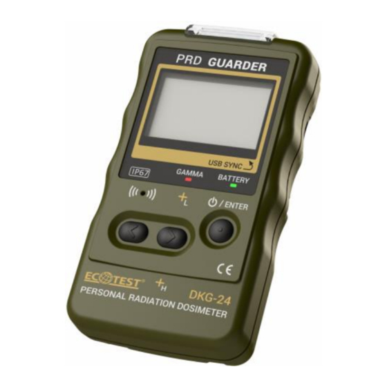
1.4 Design and principle of operation 1.4.1 General information, design description 1.4.1.1 Appearance of the device is shown in Figure 1. Figure 1 – Appearance of the device In terms of design, the device’s shape is a derivative of a rectangular parallelepiped with the replacement of planes by surfaces with large radii of curvature with rounded edges. - Page 15 The device is powered by two batteries (AA size). It is possible to operate it from lithium batteries – FR6 with a total nominal voltage of 3.0 V, from alkaline batteries with a total nominal voltage of 3.0 V and nickel-metal hydride batteries with a total nominal voltage of 2.4 V.
-
Page 16: Labeling And Sealing
the device, the GMD displays the readings of DER, flux intensity, intensity flow histogram, statistical error by gamma channels. If photon ionizing radiation DER exceeds the value of 50 μSv/h, the GSDUh automatically turns off, and the DER value is calculated from the GSDUl, which runs constantly. The photon ionizing radiation DE is also calculated from the GSDUl. -
Page 17: Proper Use Of The Device
2 PROPER USE OF THE DEVICE 2.1 Operating limitations Operating limitations are presented in Table 2.1. Table 2.1 – Operating limitations Operating limitation Limitation parameters Ambient air below minus 20 and above 50 °C temperature Effect of photon DER of photon ionizing radiation ionizing radiation is more than 100 Sv/h 2.2 Preparation for operation... -
Page 18: Use Of The Device
Table 2.2 - List of possible troubles and troubleshooting Trouble, its manifestation and Probable cause Troubleshooting additional features The device does The device batteries Change the not switch on got discharged batteries No communication USB cable damaged Replace the USB between the device cable and the personal... - Page 19 A special protective jacket is used to prevent accidental contact with conductive parts. Ingress protection rating is - IP67 according to DSTU EN 60529:2018. 2.3.1.4 Fire safety conditions are ensured by the fact that the device belongs to compact electronic devices with low energy consumption, and the absence of combustible materials used in the structure, and the critical temperature is insufficient for self-ignition.
- Page 20 You can use the navigation buttons to change the operating modes of the device, its settings, and navigate through the menu. The ENTER button serves to save settings, confirm entered data, recalibrate, switch on the device, as well as enter and exit the software update mode.
- Page 21 “Key tone” – sound and/or vibration signals generated when there was some manipulation with the device’s controls. These signals can be completely disabled. 2.3.2.4 Triggering of alarms when thresholds are exceeded When the set sigma threshold alarm level is exceeded, a flashing icon will appear in the icon display area.
- Page 22 Note 1. Calibration by the level of gamma background is done automatically when the device is switched on, or as required by the user. Calculation of the search sigma threshold level of the alarm is performed regardless of the device operating mode.
- Page 23 Regardless of the device’s operating mode, the following icons may be displayed in the upper two lines of the display: – displaying the current battery status; – displaying the current time; – displaying the navigation receiver status; – displaying the BLE module status; –...
- Page 24 2.3.3.1 Switching the device on and entering the measurement mode Hold down the ENTER button for at least 3 seconds to turn on the device. Backlight of the graphical monochrome display (hereinafter called the display) shows that the device is on, after which information about the device and the manufacturer’s trademark appears on it icon appears on the display when you try to turn on...
- Page 25 Figure 4 – Entering the administrator password Default password is “1111”. By pressing the “<”, “>” buttons, you must select the field for entering the password and press the ENTER button. By pressing the “<”, “>” buttons, you must select the desired number for each section of the password.
- Page 26 Figure 5 – Mode of DER measurement and indication This window displays the DER, the gamma radiation pulse count rate, and the estimated limits of the expected relative statistical deviations of the measurement result given the confidence probability of 0.95 (Figure 5). The resolution of the display of the gamma radiation pulse count rate is 1 cps.
- Page 27 This window displays DER, pulse count rate and gamma radiation intensity histogram, displaying pulses every 100 ms for the last 25.6 s. Resolution of gamma pulse count rate display is 1 cps. A unit of measurement is specified next to each value, according to which the data is currently displayed.
- Page 28 Rotate the device in the direction of the arrows on the display by 360º (Figure 8). Figure 8 – Gyroscope calibration: rotating the device in the direction of the arrows by 360º After rotating the device press the ENTER button. In this operating mode, the orientation of the display will change by 180º, the device must also be turned by 180º, respectively.
- Page 29 2.3.3.6 DE measurement mode Switching to the display mode of the accumulated dose is carried out by pressing the “<”, “>” buttons (depending on the current operating mode of the device) (Figure 10). Figure 10 - DE measurement mode The window displays the accumulated dose and the time since the device was turned on.
- Page 30 • Device info – information about the device and the manufacturer, • Device off – switching off the device, • Back – make the settings screen inactive. To proceed to the desired settings item, use the “<”, “>” buttons to move the cursor up or down until the cursor points to the desired item, then press the ENTER button to confirm switching to this item.
- Page 31 To change the settings in the “Display”, “Location” and “Additional settings” items, use the “<”, “>” buttons to move the cursor up or down until the desired parameter is selected, then press the ENTER button to confirm the selection. After that, use the “<”, “>”...
- Page 32 • Brightness – allows setting the display backlight intensity in the range from 0 % to 100 % in 10 % increments. • Backlight – allows setting the following display backlight time: 1 min, 2 min, 5 min or continuous backlight. •...
- Page 33 Figure 14 – Setup of vibration signals 2.3.3.7.4 Light “Light” item contains the following settings (Figure 15): Figure 15 – Setup of light signals • System light – allows enabling or disabling light signals when the device is turned on/off and when the batteries are discharged;...
- Page 34 2.3.3.7.6 Location “Location” item includes the following settings (Figure 17): Figure 17 – Setting the parameters of the navigation receiver • Receiver – allows turning on or off the power supply of the device’s navigation receiver; • Time logging – allows, in the presence of reliable coordinates, automatically recording events in the non-volatile memory at the following time intervals: 15 s, 30 s, 60 s, 120 s, 300 s;...
- Page 35 Figure 18 – Location information 2.3.3.7.7 Connectivity The “Connectivity” item contains the following settings (Figure 19): Figure 19 – Setting up connections with external devices • Bluetooth – allows connection with an peripheral device via the Bluetooth channel; • USB – allows connection with a PC via the USB bus. When USB sharing is disabled, the USB port can be used to power the device.
- Page 36 2.3.3.7.8 Measurement The “Measurement” item contains the following settings (Figure 20): Figure 20 – Measurement parameters setup • Gamma sigma threshold – allows you to set the threshold for alarm triggering based on the number of exceedances of the root mean square value of the gamma radiation pulse count rate;...
- Page 37 Up to 65,536 events can be stored in the device’s memory. If the device’s memory is full and further saving of events is impossible, when the device is turned on, an information window will appear, which will notify about memory overflow (Figure 21).
- Page 38 IMPORTANT! The option to configure “Current time” and “Current date” parameters is available only after entering the “Administrator” mode. 2.3.3.7.10 Additional settings The “Additional settings” item contains the following settings (Figure 23): Figure 23 –Additional parameters setup • Search window – allows you to choose one of the operating modes: displaying the intensity histogram by the gamma channel or displaying the search diagram.
- Page 39 2.3.3.8 Data communication with personal computer 2.3.3.8.1 Installation of software To read and review the events from the device and setting its parameters use the “Spectra Reader” software (hereinafter “Spectra Reader” SW), which is supplied by the device’s manufacturer. IMPORTANT! You need to know the password to log in as “Administrator”...
- Page 40 Note. You can find out the COM port number by right-clicking on the “Start” icon and selecting “Device Manager” in the pop-up window. After that, in the “Ports (COM and LPT)” tab, find “ST Microelectronics Virtual COM Port”. The COM port number (COM__) shown opposite this device is used to select the “Spectra Reader”...
- Page 41 2.3.3.8.3 Events reading After launching the “Spectra Reader” SW, the “Events” tab of the main window opens (Figure 26). Figure 26 – “Events” tab In the upper left corner of the “Events” tab, a serial number of the connected device appears in the format “Serial number XXXXXXXXX”, where XXXXXXXXX is a unique serial number of the currently connected device.
- Page 42 2.3.3.8.4 Working with the readout events After successfully reading the events from the device, they will be displayed in the “Events list” field of the “Events” tab (Figure 27). Figure 27 – Readout events Select the required event in the “Events list” field. The information it contains is displayed rightwards below the “Events filter”...
- Page 43 The upper right corner of the “Events” tab contains the following buttons of the events control: – saving all events to the PC’s hard drive in the .dat format (including those that are not displayed according to filters); – download the saved events from the PC’s hard drive; –...
- Page 44 2.3.3.8.5 Settings Go to the “Settings” tab of the main window of the “Spectra Reader” SW (Figure 29) and click the “Read Settings” button to read the current data from the device. Figure 29 – Settings tab The “Settings” tab has the following fields: •...
- Page 45 After entering the required data and checking the fields to be recorded with, click the “Save settings” button to save the updated data to the device’s memory. • Threshold by dose – in this field, you can set the alarm trigger threshold based on the accumulated dose.
- Page 46 • Repeat new PIN code – renter the new access PIN code in this field. Click “Apply” to save the new PIN code or “Cancel” to keep the current PIN code unchanged. 2.3.3.8.7 Map On the “Map” tab of the main window of the “Spectra Reader”...
-
Page 47: Technical Maintenance
3 TECHNICAL MAINTENANCE 3.1 Technical maintenance of the device 3.1.1 General guidelines The list of operations during technical maintenance (hereinafter – the TM) of the device, the order of priority and features at different stages of the device use is shown in Table 3.1. -
Page 48: Verification Of The Device
b) check the condition of the of the USB connector pins. 3.1.3.2 Delivery kit completeness check Check if the delivery kit is complete according to Table 1.2. 3.1.3.3 Operability check of the device 3.1.3.3.1 Operability check of the device and its procedure are performed according to OM 2.3.3. -
Page 49: Certificate Of Acceptance
4 CERTIFICATE OF ACCEPTANCE The DKG-24 “PRD GUARDER” personal radiation ВIСТ.412139.009-02 with ______________________ serial number is verified and accepted for use. Date of issue _____________________________________ QCD representative ______________________ Seal here (signature) -
Page 50: Packing Certificate
5 PACKING CERTIFICATE The DKG-24 “PRD GUARDER” personal radiation ВIСТ.412139.009-02 with ______________________ serial number is packed by the PE “SPPE “Sparing-Vist Center” in accordance with the requirements outlined in the OM. Date of packing ____________________________________ Seal here Packed by _________________________ (signature) -
Page 51: Warranty
6 WARRANTY 6.1 The producer enterprise guarantees the conformity of the device with the technical requirements provided that the customer observes the guidelines on its use, shipping and storage presented in the OM ВIСТ.412139.009-02 НЕ. 6.2 The warranty period of the device shall terminate and be of no further effect in 24 months after the date of putting it into operation or after the warranty period of storage terminates. -
Page 52: Repair
PE “SPPE “Sparing-Vist Center” 79026, Ukraine, Lviv, 33 Volodymyra Velykoho Str. Tel.: (+38032) 242 15 15, fax: (+38032) 242 20 15 E-mail: sales@ecotest.ua 7.2 All claims are registered in Table 7.1. Table 7.1 Date of... -
Page 53: Storage
8 STORAGE 8.1 The devices should be stored in the packing box in heated and ventilated storehouses with air-conditioning at the ambient air temperature from + 5°С to +40°С and relative humidity up to 80 % at +25°С temperature, non-condensing. The storehouse should be free of acids, alkalis and gases that may cause corrosion, and vapors of organic solvents. -
Page 54: Transportation
9 TRANSPORTATION 9.1 Packed devices allow transportation in any type of closed vehicle where temperature and humidity fluctuations are slightly different from fluctuations in the open air, at temperatures from minus 25°C to 60°C and relative humidity of 80% at a temperature of 25°C according to the rules and regulations in force for each type of transport. -
Page 55: Disposal
10 DISPOSAL Disposal of the device must be carried out in accordance with the Laws of Ukraine “On environmental protection” and “On waste”. Disposing of the device is not dangerous for the service personnel, and is environmentally friendly. -
Page 56: Annex А
ANNEX А TROUBLE RECORD DURING USE... -
Page 57: Annex B
ANNEX B PERIODIC VERIFICATION OF MAIN SPECIFICATIONS Characteristic under Date of measurement verification Year 20 Year 20 Year 20 Standardized Name value Main relative permissible error when measuring 15+2/М, photon ionizing where М – radiation DER with a dimensionless confidence value, probability of numerically... -
Page 58: Annex C
ANNEX C В INFORMATION ON DEVICE REPAIR... -
Page 59: Annex D
ANNEX D STORAGE Date Position, name and Storage signature of of placing in of placing conditions storage in storage responsible person... -
Page 60: Annex E
ANNEX E PUTTING IN PROLONGED STORAGE AND REMOVAL FROM STORAGE Date of Name of the Date, position removal enterprise in charge Storage and signature of from of putting or method the responsible prolonged removing from person storage prolonged storage... -
Page 61: Annex F
ANNEX F VERIFICATION AND INSPECTION RESULTS Position, name Verification and signature of Verification or Date or inspection the person inspection result type responsible for inspection...
Need help?
Do you have a question about the PRD GUARDER DKG-24 and is the answer not in the manual?
Questions and answers