Table of Contents
Advertisement
Quick Links
Advertisement
Table of Contents

Related Manuals for ECOTEST DoseG


Summary of Contents for ECOTEST DoseG
- Page 1 EPD-27 ELECTRONIC PERSONAL DOSIMETER Operating Manual ВІСТ.412118.046-01 НЕ...
-
Page 3: Table Of Contents
CONTENTS 1 DESCRIPTION AND OPERATION ..6 1.1 P ..6 URPOSE OF USE OF THE DOSIMETER 1.2 T ....9 ECHNICAL PECIFICATIONS 1.3 D ..30 ELIVERY KIT OF THE DOSIMETERS ’ 1.4 D OSIMETER S DESIGN AND PRINCIPLE OF ........... - Page 4 2.2 P REPARATION OF THE DOSIMETER FOR ..........52 OPERATION 2.3 U ......60 SE OF THE DOSIMETER 3 TECHNICAL MAINTENANCE ... 107 3.1 T ECHNICAL MAINTENANCE OF THE ..........107 DOSIMETER 3.2 V ..115 ERIFICATION OF THE DOSIMETER 4 CERTIFICATE OF ACCEPTANCE ..
- Page 5 8 STORAGE ..........150 9 TRANSPORTATION ......152 10 DISPOSAL .......... 155 ANNEX А..........156 ANNEX B ..........157 ANNEX C ..........158 ANNEX D..........159 ANNEX E ..........163 ANNEX F ..........165...
- Page 6 This operating manual (OM) is intended to give insights into the principle of operation of the EPD-27 "DoseG", EPD-27 "DoseGX" Electronic Personal Dosimeters, their proce- dure of operation, and contains all the infor- mation necessary for comprehensive utiliza- tion of their technical capabilities and their proper use.
- Page 7 - individual dose equivalent; - individual dose equivalent rate; - unified access station from the kit of SHS(u)ASIDC; SHS(u)ASIDC - software hardware suite (unified) of the automated sys- tems of individual dosimetry control of personnel; - storage and charging device; - strict access area;...
-
Page 8: Description And Operation
1 DESCRIPTION AND OPERATION 1.1 Purpose of use of the dosimeter Electronic personal dosimeters EPD-27 are made in two modifications (see Table 1.1): Table 1.1 Designation Code ВІСТ.412118.043-01 EPD-27 "DoseG" ВІСТ.412118.043-03 EPD-27 "DoseGХ"... - Page 9 EPD-27 "DoseG", EPD-27 "DoseGX" Electronic Personal Dosimeters are designed for use as part of an automated system of indi- vidual dosimetry control and a stand-alone use in order to: - measure the individual dose equivalent (DE) of gamma and X-ray radia-...
- Page 10 - measure the individual dose equivalent rate H (DER) of gamma and X-ray radiation (hereinafter – photon ionizing radiation); - monitor the duration of stay of the person- nel in the area under control; - managing an automated database of radia- tion burden on personnel within the software and hardware suite (unified) of the automated system of individual dosimetry control of personnel.
-
Page 11: Technical Specifications
Electronic Personal Dosimeter "DoseG" (EPD-27 "DoseGX") (hereinafter – the dosimeter) can be used at nuclear power plants, in medicine, industry, radiological la- boratories and institutions that deal with sources of photon ionizing radiation. The dosimeter meets the requirements of the international standard IEC 61526:2005. - Page 12 Table 1.2 Unit of Standardized val- Name meas- ues according to Specifications Measurement range of μSv 1 – 10 photon ionizing radia- tion DE Display range of pho- μSv 0.1 – 10 ton ionizing radiation...
- Page 13 Table1.2 (continued) Measurement range μSv/h 10 – 10 of photon ionizing radiation DER 1 – 10 when DER is less Display range of than 1 μSv/h, the μSv/h photon ionizing ra- "Lo" symbol is dis- diation DER played on the do- simeter’s LCD...
- Page 14 Table1.2 (continued) Main relative permissible error limit of DE measurement at Cs calibration with 0.95 confidence probability, not more than Main relative permissible error limit of DER measurement in percentage at calibration with 0.95 confidence probabil- ity, not more than - within 10 μSv/h to 1 mSv/h: - within 1 mSv/h to 10 sV/h:...
- Page 15 Table1.2 (continued) Anisotropy at solid angle of 60° relative to the main (perpendicular to the front panel of the dosimeter) direction of measurement: - for radionuclides Cs and 25 not more than - for radionuclide Am, not more 60 than...
- Page 16 Table1.2 (continued) Complementary relative permissi- ±5 ble error limit of photon ionizing per each radiation DER and DE measure- о С of ment result caused by ambient tem- deviation С, in the perature deviation from 20 from temperature range from minus 20 to о...
- Page 17 Table1.2 (continued) Time of continuous operation of the dosime- ter under normal climatic conditions when powered from a fully charged battery: - under gamma background not more than 0.5 μSv/h and with switched off LCD back- light, switched off sound and vibration alarm, not less than - under the conditions of DER measurement equal to 1 Sv/h and with switched on LCD...
- Page 18 Table1.2 (continued) Unstable readings of the dosimeter during 8 hours of continuous opera- tion, not more than Mean life of the dosimeter (includ- year ing repairs), not less than Mean time to failure, at least 6000 Mean time to recovery of the do- simeter...
- Page 19 Table1.2 (continued) Mean shelf life of the do- simeter provided that the battery is charged 6 year months after the begin- ning of storage, at least Dimensions of the dosim- eter with a clip, not more mm 84.555.024.5 than Weight of the dosimeter, 0.11 not more than...
- Page 20 Table1.3 50 – Energy range of detected photon ionizing radiation by EPD-27 "DoseG" dosimeter keV 10 000 Energy dependence of EPD-27 "DoseG" dosimeter when measuring photon ioniz- ing radiation DER and DE relative to 662 keV energy( Cs), not more than 25...
- Page 21 Table1.3 (continued) 15 – Energy range of detected photon ionizing radiation by EPD-27 "DoseGX" dosimeter 10 000 Energy dependence of EPD-27 "DoseGX" dosimeter when measuring photon ionizing radiation DER and DE relative to 662 keV energy( Cs), not more than - in the energy range from 16 keV tо...
- Page 22 1.2.2 The dosimeter displays "nnnn" char- acters when it measures DER as a sign of DER exceeding the upper limit of the range when it is irradiated with DER from 12.0 Sv/hour to 20.0 Sv/hour. 1.2.3 The dosimeter records the events of DER exceeding the upper limit of the meas- urement range and displays the occurrence of such events by flashing DER value in its dis-...
- Page 23 1.2.4 The dosimeter’s detector self-testing is carried out continuously during its opera- tion. In the event of the detector’s failure, the dosimeter generates typical sound, vibration and light signals, and displays an "Er01" fail- ure sign on the LCD. 1.2.5 The residual battery charge is contin- uously evaluated during operation of the do- simeter.
- Page 24 1.2.6 The dosimeter features an option to test the display and signaling tools. 1.2.7 The dosimeter allows programming the values of: - warning and emergency threshold levels of photon ionizing radiation DE in the range from 1 μSv to 9.999 Sv with 1 μSv resolution; - warning and emergency threshold levels of photon ionizing radiation DER in the range from 10 μSv/h to 9.999 Sv/h with 1 μSv/h res-...
- Page 25 - warning and permissible duration of stay in the SAA in the range from 1 min to 1 min to 99 h 59 min. 1.2.8 Threshold level values can be pro- grammed manually or during information ex- change with the UAS or the USB/IrDA adapter. 1.2.9 The dosimeter generates typical sound, light and vibration signals in case of exceeding the threshold (emergency and warning) levels of...
- Page 26 1.2.10 The dosimeter reduces the intensity of vibration signal in 30 seconds after the start of its generation. 1.2.11 The dosimeter displays the duration of stay in the SAA in the form of a direct or reverse timer. The display format is selected during the data exchange with the UAS or USB/IrDA adapter.
- Page 27 and DE and completing the warning duration of stay in the SAA. 1.2.13 The non-volatile memory of the dosimeter stores the following: - current DE value; - maximum value of photon ionizing radiation DER value (with a statistical error of not more than 25 %);...
- Page 28 - when DER threshold levels start and stop to be exceeded; - when DE threshold levels start to be ex- ceeded; - all events have to be stored with reference to time. 1.2.14 The interval, at which dose accumula- tion history values are stored, is programmed in the range from 5 to 255 minutes with an one-mi- nute increment.
- Page 29 1.2.15 The dosimeter adjustment and reading the history of events and dose accumulation his- tory is done during information exchange with the UAS or USB/IrDA adapter. 1.2.16 The dosimeter is equipped with a charger. The charging time of the dosimeter’s fully discharged battery does not exceed 5 hours.
- Page 30 1.2.17 The dosimeter is resistant to the follow- ing operating conditions: - temperature – from –20 С to +50 С; - relative humidity – up to (95 3) % at tem- С; perature 35 - atmospheric pressure – from 84 to 106.7 kPa. 1.2.18 The dosimeter is resistant to sinusoidal vibrations by group N1 in compliance with GOST 12997-84 standard at a frequency from 10 Hz to...
- Page 31 1.2.19 The dosimeter is resistant to 60 re- peated shocks, each shock corresponding to a drop from a height of 10 cm onto a hard steel surface (DSTU IEC 60068-2-31:2013 standard). 1.2.20 The dosimeter withstands 6 drops (one drop on each side) from a height of 1.0 m onto a hard surface (DSTU IEC 60068-2-31:2013 standard).
-
Page 32: Delivery Kit Of The Dosimeters
1.3 Delivery kit of the dosimeters 1.3.1 The dosimeters’ delivery kit includes the products and operating documentation listed in Tables 1.4 and 1.5. - Page 33 Table 1.4 - Delivery kit of EPD-27 "DoseG" dosimeter Quan- Type Item Note tity EPD-27 "DoseG" ВІСТ.412118.043- Electronic Per- sonal Dosimeter ВІСТ.412118.046- Operating 01 НЕ manual ВІСТ.412915.051 Packaging...
- Page 34 Table 1.5 - Delivery kit of EPD-27 "DoseGX" dosimeter Quan- Type Item Note tity EPD-27 ВІСТ.412118.043- "DoseGX" Elec- tronic Personal Dosimeter ВІСТ.412118.046- Operating 01 НЕ manual ВІСТ.412915.051- Packaging...
- Page 35 When purchasing a batch of dosimeters for use in the automated dose control system for a large number of users, it is possible to additionally supply devices for charging and storing SCDs (for 40 dosimeters) and a device for program- ming/reading dosimeters –...
-
Page 36: Dosimeter's Design And Principle Of Operation
supply the USB/IrDA adapters with the appropri- ate software. 1.4 Dosimeter’s design and principle of operation 1.4.1 Design of dosimeter. The dosimeter (as shown in Figure 1.1 and in Figure 1.2 depending on the modification) is de- signed as a rectangular parallelepiped whose planes are replaced with the surfaces of large radii of curvature and rounded edges. - Page 37 The shape and dimensions of the dosimeter were chosen for the convenience of its main way of use, namely – when worn for a long time in the upright position in a breast pocket of the overalls. The dosimeter’s housing is made of impact- resistant glass-filled plastic.
- Page 38 On the face beveled end of the dosimeter, there is a screen with illumination of the liquid crystal display (LCD) that is divided into two parts (5) and (6), as well as two light-emitting diode (LED) indicators – (7) “Alarm” and (8) CHARGE.
- Page 39 “+”, showing a mechanical center projection of the detector that is located under a cover at the depth of 7.2 mm. Two circular contact pads (14) are located on the bottom cover for connecting the charger, a window (15) for data communication with external devices via an infrared port, and a hook (16) for attaching a neck strap cord when clothes with breast pockets are unavailable.
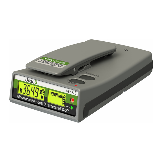
- Page 40 Figure 1.1 – Appearance of EPD-27 "DoseG" do- simeter (overhead view)
- Page 41 Figure 1.2 - Appearance of EPD-27 "DoseGX" do- simeter (overhead view)
- Page 42 1.4.2 Basic Operation of the Dosimeter The dosimeter is presented as a monoblock unit, comprising: - photon ionizing radiation detector (D); - processing unit (PU); - LCD; - indicating unit (IU); - alarm buzzer (AB); - LiPo battery (B). The dosimeter’s block diagram is shown in Figure 1.3.
- Page 43 Figure 1.3 - Dosimeter’s block diagram...
- Page 44 The photon ionizing radiation detector (D) consists of an interconnected silicon photo- multiplier and a scintillator (YSO(Ce)). For thermocompensation of the detector’s charac- teristics, it also includes a thermal detector. The processing unit is a microcontroller (MC)-based unit. It comprises: Supply voltage former (SVF);...
- Page 45 Li-polymer battery charging unit (BCU); non-volatile memory (NVM); infrared port (IP); vibrating motor (VM); MODE and THRESHOLD buttons; amplifier (A). All elements of the processing unit are as- sembled on a single board. A photon ionizing radiation detector is also installed on the same board.
- Page 46 The LCD is a sign & character liquid crys- tal display with a LED backlight. The LCD is connected to the processing unit using a connector. The indicating device is designed as a flex- ible board with the “Alarm” and CHARGE LEDs located on it.
- Page 48 The operating principle of the detector is based on the transformation of scintillations, caused by photon ionizing radiation in a scin- tillator, by the silicon photomultiplier into pos- itive polarity pulses. The number of these pulses is proportional to photon ionizing radi- ation DER, whereas the amplitude –...
- Page 49 The microcontroller measures the pulse frequency and makes its amplitude analysis. Based on this information and scaling coeffi- cients that are stored in its non-volatile memory, the microcontroller produces meas- urement results of photon ionizing radiation DER and DE. The history of DER accumulation and events is stored in the non-volatile memory.
- Page 50 The supply voltage former converts LiPo battery voltage into stabilized voltages to power the dosimeter’s units. The bias voltage former of the photomulti- plier generates voltage to power the photomul- tiplier. The charging unit of the LiPo battery charges the dosimeter’s battery at +5 V volt- age, which is applied to the terminals of the dosimeter from an external power supply.
-
Page 51: Labeling And Sealing
1.5 Labeling and sealing 1.5.1 The dosimeter’s front panel contains the name and the symbol of the device, an ap- proval mark of the measurement instrument type, CE marking for goods and services, and the ingress protection rating. 1.5.2 The bottom cover contains the fac- tory serial number and the date of manufacture of the dosimeter, as well as the approval mark of the measurement instrument type, CE mark-... - Page 52 1.5.3 The trademark of the manufacturer is affixed to the clip. 1.5.4 The dosimeter is sealed by the man- ufacturer with a paste, which closes the head of one of the screws that fasten the covers of the body with each other. 1.5.5 Removal of seals and repeated seal- ing is carried out by the organization in charge of repair and calibration of the dosimeter.
-
Page 53: Packaging
1.6 Packaging 1.6.1 The dosimeter, together with the op- erational documentation, is supplied in a card- board box. 1.6.2 The box is fitted into a polyethylene film pouch that is welded after packaging. -
Page 54: Proper Use
2 PROPER USE 2.1 Operating limitations Operating limitations are presented in Table 2.1. 2.2 Preparation of the dosimeter for operation 2.2.1 The scope and procedure of external examination 2.2.1.1 Before using the dosimeter, unpack it and examine for mechanical damages. - Page 55 Table 2.1 – Operating limitations Operating limitation Operating limitation parameters name 1 Ambient air tem- о о С to +50 С from - 20 perature 2 Relative humidity up to 95 % at a temperature о С, non-condensing of 35 3 Atmospheric from 84 kPa to 106.7 kPa pressure...
- Page 56 2.2.2 Rules and procedure of examination for operational readiness 2.2.2.1 Read this OM carefully before starting the operation. 2.2.2.2 By long press of the MODE button, switch the dosimeter from the "Sleep" to the "Standby" mode, as indicated by the LCD characters "StOp"...
- Page 57 ing to 2.3.3.2 of this OM before the start of op- eration. By briefly pressing the THRESHOLD button, start the test mode of the dosimeter dis- play and signaling means. Make sure that the dosimeter’s LCD is backlit, all its segments and "Alarm" LED in- dicators are highlighted, as well as a triple sound and vibration alarm is generated.
- Page 58 2.2.3 List of possible troubles and trouble- shooting 2.2.3.1 The list of possible troubles and troubleshooting is presented in Table 2.2. Troubles during usage period shall be regis- tered in the Table of the Annex C of the OM.
- Page 59 Table 2.2 - Possible troubles and trouble- shooting Probable Solution Trouble cause When the MODE button Storage Charge is pressed, the dosimeter battery is the stor- does not switch from age bat- "Sleep" to "Standby" tery mode...
- Page 60 Table2.2 (continued) Send In the mode of the dosim- the do- eter display and signaling simeter means testing: for re- pair to Failure of - not all segments of the LCD LCD are highlighted; manu- facturer Failure of - LCD backlight does not the LCD switch on;...
- Page 61 Table2.2 (continued) Send the do- - vibration alarm Failure of vi- simeter for is not generated; brating motor repair to the - LED indicators LEDs failure manufacturer "Alarm" are not highlighted "Er01" symbol on Failure of pho- Send the do- the LCD of the ton ionizing ra- simeter for...
-
Page 62: Use Of The Dosimeter
2.3 Use of the dosimeter 2.3.1 Safety measures during use of the dosimeter 2.3.1.1 All works with ionizing radiation sources during calibration and testing of the dosimeter shall be carried out in accordance with the requirements of DGN 6.6.1.-6.5.001- 98 and DSP 6.177-2005-09-02 standards. 2.3.1.2 The dosimeter must be used in ac- cordance with the instructions given in the... - Page 63 2.3.1.3 The dosimeter shall meet the require- ments of DSTU EN 61010-1:2014 standard. 2.3.1.4 A protective shell shall be used to en- sure protection against accidental contact with conductive parts in the dosimeter. The ingress protection rating is ІР67 in ac- cordance with DSTU EN 60529:2018 standard.
- Page 64 2.3.2 Operating modes of the dosimeter The dosimeter operates within the follow- ing modes: "Sleep"– used for storage in the ware- house. All units of the dosimeter are off, the consumption is minimum, the dosimeter re- sponds only to presses of the MODE button in this mode.
- Page 65 "Standby" – waiting for information ex- change with the UAS or USB/IrDA adapter, it is used during operation while the dosimeters are in the SCD. The dosimeter in this mode re- sponds to queries via the infrared interface and buttons pressing. Consumption of the dosime- ter is increased compared to the "Sleep"...
- Page 66 "Operation": – DE display; – DE display; – Real time display; – Display of time spent in the SAA/time left before leaving the SAA. 2.3.3 Procedure of the dosimeter operation 2.3.3.1 Dosimeter’s controls The MODE (10) and THRESHOLD (11) buttons (Figure 1.1 and Figure 2.2) are in- tended to control the dosimeter.
- Page 67 The MODE button serves to switch between the dosimeter’s operating and display modes. The THRESHOLD button is intended for viewing the current and programming the new values of alarm triggering threshold levels. 2.3.3.2 Storage battery charging 2.3.3.2.1 The battery needs to be charged by using the SCD or the USB/IrDA adapter.
- Page 68 2.3.3.2.2 The battery has to be charged at am- С. bient temperature of 0 to 40 2.3.3.2.3 The dosimeter is powered from a LiPo battery with no memory effect. That type of battery can be charged regardless of its remain- ing charge.
- Page 69 - red – charging is in process; - green – charging is complete. 2.3.3.3 General algorithm for dosimeter op- eration control When stored at a warehouse, the dosimeter shall be in the “Sleep” mode. In this mode, all dosimeter’s units are turned off and the power consumption is minimum.
- Page 70 six months until the fully charged battery be- comes fully discharged. Before the use of the do- simeter, switch it to the “Standby” mode with a long press of the MODE button. The display of “StOP” characters on the LCD indicate that the dosimeter switched to the “Standby”...
- Page 71 mode only during data communication with the UAS or USB/IrDA adapter. “IrdA” characters on the dosimeter’s LCD indicate that data com- munication is in process. A detailed description of the data communication between the dosime- ter and the UAS is given in 2.3.3.10 of this OM. DE that appears on the LCD indicates that the dosimeter has switched to the “Operation”...
- Page 72 – DE display; – DER display; – Real time display; – Display of time spent in the SAA/time left before leaving the SAA. A detailed description of each display mode is given below. The dosimeter can be switched from the “Standby”...
- Page 73 button switches the dosimeter from the “Standby” to the “Sleep” mode. 2.3.3.4 LCD backlight control In the “Operation” mode, each press of any dosimeter’s button turns on the LCD backlight for about 6 seconds. For continuous LCD back- light, press the THRESHOLD button twice (the time between presses should not exceed 0.5 s).
- Page 74 2.3.3.5 Control of the remaining battery charge In the “Operation” mode, the dosimeter constantly monitors the remaining battery charge. The control results are displayed on the LCD as a battery status symbol consist- ing of four segments. With a fully charged bat- tery, all the status symbol segments are illumi- nated.
- Page 75 first, then the second one, etc. When the bat- tery is completely discharged, none of the seg- ments is illuminated. The battery status sym- bol blinks and short-term audio signals are generated. 2.3.3.6 Display of photon ionizing radia- tion DER 2.3.3.6.1 After being switched from the “Standby”...
- Page 76 dosimeter starts displaying photon ionizing radia- tion DE. Switching to the DE display mode is possible from any other display mode by briefly pressing the MODE button. 2.3.3.6.2 The dosimeter’s LCD shows the following information (Figure 2.1): - (1) “D” symbol indicates the display mode of DE;...
- Page 77 Figure 2.1 – LCD of the dosimeter (display of photon ionizing radiation DE). The value of DE is blinking if an event(s), where DER exceeds the upper limit of the measurement range, occurs during DE accu- mulation.
- Page 78 When one of the DE threshold levels is ex- ceeded, the dosimeter starts generating typical audio, light, and vibration signals. A relevant transparency is displayed on the dosimeter’s LCD, showing WARNING – if the warning threshold level is exceeded, or ALARM – if the emergency threshold level is exceeded.
- Page 79 After turning off the alarm, the WARNING transparency remains on the dosimeter’s LCD. 2.3.3.6.3 To view the current DE threshold levels, press and hold the THRESHOLD button. In this case, both warning and emergency thresh- old levels will be displayed alternately on the LCD (as shown in Figure 2.2 and 2.3).
- Page 80 Figure 2.2– LCD of the dosimeter (display of the warning threshold level). Figure 2.3 – LCD of the dosimeter (display of the emergency threshold level).
- Page 81 After the THRESHOLD button is released, the threshold level will be shown for 2 more seconds on the LCD, and then the dosimeter will switch to DE display. To program the value for the warning or emergency DE threshold level, do the following: - Press the THRESHOLD button and hold it until the LCD shows a necessary threshold...
- Page 82 - Release the THRESHOLD button, and while the LCD is still displaying this thresh- old, briefly press the MODE button. If there was no prohibition to change threshold levels during data exchange with the UAS or USB/IrDA adapter, the low-order digit of a new threshold value will start blinking, meaning that it can be programmed.
- Page 83 THRESHOLD button change the value per unit. A long press of the THRESHOLD button automatically changes the value and ceases to do this after releasing the THRESHOLD button. A short press of the MODE button records a value of this digit position. Moreover, this digit stops blinking, making it possible to change the value of the next digit that starts blinking.
- Page 84 As soon as the threshold level is set, its value is blinking on the LCD three times, in- dicating that it is stored in the dosimeter’s non- volatile memory. After that, the dosimeter re- turns to the display mode of photon ionizing radiation DE.
- Page 85 changes made while programming the new threshold value are canceled. Note. Setting the threshold level to a zero value turns off the alarm. 2.3.3.7 Display of photon ionizing radia- tion DER 2.3.3.7.1 Switching to the DER display mode is possible from any other display mode by briefly pressing the MODE button.
- Page 86 2.3.3.7.2 The dosimeter’s LCD shows the fol- lowing information (Figure 2.4): - (1) “R” symbol indicates the DER display mode; - (2) DER value; - (3) Battery status symbol. Figure 2.4 – LCD of the dosimeter (display of photon ionizing radiation DER).
- Page 87 If the DER value is less than 1 μSv/h, then “LO” characters are displayed on the dosime- ter LCD instead of the DER value. If the DER value is greater than 12 Sv/h, the LCD shows “nnnn” characters. The decimal point of the DER value is blinking if the estimated limits of the expected relative statistical deviations of a DER value at confidence probability of 0.95 (here-...
- Page 88 1 mSv/h and more than 10% for DER in the range from 1 mSv/h to 10 Sv/h. When one of the DER threshold levels is exceeded, the dosimeter begins generating typical sound, light, vibration signals. A rele- vant transparency is displayed on the dosime- ter LCD, showing WARNING –...
- Page 89 The alarm actuated on exceeding the warn- ing threshold level can be disabled with a long press of the THRESHOLD button (for about 8 seconds). After turning off the alarm, the WARNING transparency remains on the do- simeter LCD. 2.3.3.7.3 Viewing the current threshold level values and programming the new values is done in the same way as viewing and pro- gramming the DE threshold levels (2.3.3.6.3).
- Page 90 2.3.3.8 Real time display 2.3.3.8.1 You can switch to the mode of real time display from any other display mode by briefly pressing the MODE button. This mode is the next one after the DER display mode. 2.3.3.8.2 The following information is dis- played on the dosimeter LCD (Figure 2.5): - (1) time;...
- Page 91 Figure 2.5 – LCD of the dosimeter (display of time). 2.3.3.8.3 To view the date and year, one must press and hold the THRESHOLD button. In this case, the date (Figure 2.6) or year (Figure 2.7) will alternately appear on the dosimeter LCD.
- Page 92 Figure 2.6 – LCD of the dosimeter (date display). Figure 2.7 – LCD of the dosimeter (year display).
- Page 93 Two seconds after the THRESHOLD button is released, the time on the LCD of the dosimeter will be displayed again. 2.3.3.8.4 To adjust the time, date and year, if this was not prohibited during data communica- tion with the UAS or the USB/IrDA adapter, briefly press the THRESHOLD button.
- Page 94 Blinking digits indicate the possibility of their values programming. The required value is set with the THRESHOLD button. Consecutive short presses and releases of the THRESHOLD button change the value per unit. A long press of the THRESHOLD button automatically changes the value that stops when the THRESHOLD button is released.
- Page 95 blinking. Programming the digits of hours is done using the THRESHOLD button similarly to pro- gramming the digits of minutes. A short press of the MODE button records a new time value in the dosimeter’s memory, after which the LCD displays a year. The low-order digits of the year are blinking, indicating the possibility to program their value.
- Page 96 A short press of the MODE button records a new value of the year in the dosimeter’s memory. After that, the LCD displays the date and month. The digits of the months are blinking, indicating the possibility to program their value. Program- ming is done with the THRESHOLD button sim- ilarly to programming of the minute’s digit.
- Page 97 blinking. Programming the date digits is done us- ing the THRESHOLD button similar to program- ming of the hour digits. A short press of the MODE button records a new value of the date and month in the dosime- ter’s memory, as evidenced by a triple blinking of the new value on the LCD and return of the do- simeter to time display.
- Page 98 2.3.3.9.1 You can switch to the mode of dis- playing the time spent in the SAA/time left before leaving the SAA from any other display mode by shortly pressing the MODE button. This mode is the next one after the real time display mode. 2.3.3.9.2 The following information is dis- played on the dosimeter’s LCD (Figure 2.8): - (1) Time spent in the SAA/time left before...
- Page 99 The time is displayed in the HH:MM format, where HH - hours, MM - minutes. Figure 2.8 – LCD of the dosimeter (display of time spent in the SAA/ time left before leaving the SAA).
- Page 100 2.3.3.9.3 The display mode of the dosime- ter operation (time spent in the SAA in the for- mat of the direct timer, or time left before leav- ing the SAA in the format of the reverse timer) is programmed during data communication with the UAS or USB/IrDA adapter.
- Page 101 and permissible time of stay in the SAA can be programmed within this range. When the warning or permissible time of stay in the SAA is completed, the dosimeter begins generating typical sound, light and vi- bration signals and the relevant transparency is displayed on the dosimeter LCD, showing WARNING –...
- Page 102 changed at any time using the dosimeter but- tons, if not prohibited during the data commu- nication with the UAS or USB/IrDA adapter. Signaling about the completion of warning time of stay in the SAA can be turned off by a long press of the THRESHOLD button (about 8 seconds).
- Page 103 and programming of the new values is per- formed similarly to viewing and programming of the DE threshold levels (2.3.3.6.3). 2.3.3.9.6 If the time left before leaving the SAA is displayed in the reverse timer format, the time begins to count from the permissible time of stay in the SAA and decreases to 0 hours 0 minutes.
- Page 104 the dosimeter begins generating typical sound, light and vibration signals, and the relevant transparency is displayed on the dosimeter LCD, showing WARNING – if the warning time left before leaving the SAA is reached, or ALARM – if the timer is reset. The warning time left before leaving the SAA can be changed at any time using the dosimeter but- tons, if not prohibited during the data commu-...
- Page 105 2.3.3.9.7 Viewing the current value of the warning time left before leaving the SAA and programming its new value is done similarly to viewing and programming of the warning DE threshold level (2.3.3.6.3). The permissi- ble time of stay in the SAA cannot be adjusted. 2.3.3.10 Data communication of the do- simeter with the UAS or USB/IrDA adapter.
- Page 106 can be carried out at any time, if the dosimeter is in the "Standby" or "Operation" modes. To do this, you need to place the dosimeter in the cell of the UAS or USB/IrDA adapter. The "IrdA" characters on the dosimeter LCD mean the start of data communication.
- Page 107 - current DE; - maximum DER value; - dose accumulation history; - history of events; and communicate to the dosimeter: - current time; - warning and emergency threshold levels of DE; - warning and emergency threshold levels of DER;...
- Page 108 - permissible time spent in the SAA and time left before leaving the SAA and timer’s operating mode (direct or countdown); - interval of dose accumulation history val- ues recording; - permissions/prohibitions to change some threshold levels.
-
Page 109: Technical Maintenance
3 TECHNICAL MAINTENANCE Technical maintenance dosimeter 3.1.1 General instructions The list of operations performed during technical maintenance (hereinafter called the TM), the order and the peculiarities of opera- tional phases are presented in Table 3.1. - Page 110 Table 3.1 – List of operations during the TM TM type During Long-term storage period- period- Opera- item eve- ical periodical ical tions ryday use (every (annu- 6 months) (annu- ally) ally) External exami- 3.1.3.1 nation...
- Page 111 Table3.1 (continued) Delivery kit completeness 3.1.3.22 check Performance check 3.1.3.3 2.3.3.2 Battery charging 3.1.3.4 Verification of the dosim- eter Note. “+” means that the operation is applicable for this type of TM, “–” - the operation is inapplicable.
- Page 112 3.1.2 Safety measures Safety measures while carrying out TM fully comply with safety measures stated in 2.3.1 of the present OM. 3.1.3 Maintenance procedure dosimeter 3.1.3.1 External examination Check the technical condition of the do- simeter’s surface, inspect for integrity of seals, absence of scratches, traces of corrosion, sur- face damage.
- Page 113 3.1.3.2 Delivery kit completeness check Check the delivery kit for completeness as shown in Table 1.2. 3.1.3.3 Operability check of the dosimeter 3.1.3.3.1 Operability check of the dosime- ter and its procedure is done according to 2.2.2 of this OM. 3.1.3.3.2 Procedure for pre-repair fault de- tection and rejection...
- Page 114 The need to send the dosimeter for repair and the type of repair is determined by the fol- lowing criteria: - for mid-life repair: а) deviation of parameters from control values during periodic verification of the do- simeter; b) minor defects of the LCD that do not affect the correct readings of measurement results;...
- Page 115 d) no sound alarm; - for major repair: а) at least one measurement channel is out of service; b) defects of the LCD that affect the cor- rect read-out of measurement results; c) serious mechanical damage to the parts that affect the security access to the dosimeter circuit.
- Page 116 3.1.3.4 Battery charging When the dosimeter is stored for a long time, its battery needs to be recharged every six months. If this requirement is not observed, the battery is discharged and becomes out of order. Charging is performed according to 2.3.3.2 of this OM, and the dosimeter should be in the “Sleep”...
-
Page 117: Verification Of The Dosimeter
3.2 Verification of the dosimeter The dosimeters should be verified after re- pair and during operation (periodical verifica- tion – at least annually). 3.2.1 Verification operations During verification the operations listed in Table 3.2 should be performed. - Page 118 Table 3.2 – Verification operations Verification Operation technique External examination 3.2.4.1 Testing 3.2.4.2 Calculation of the main relative per- missible error limit of photon ionizing 3.2.4.3 radiation DER measurement Calculation of the main relative per- missible error limit of photon ionizing 3.2.4.4 radiation DE measurement...
- Page 119 3.2.2 Verification facilities During verification, the following facilities should be used: - УПГД-3В Хд1.456.183 ПС reference equip- ment; - УГВ2 ДЕТУ 12-06-02 reference equipment; - Phantom. Overall dimension: 30 cm30 cm15 cm; PMMA walls (polymethylmethacrylate, front wall thickness – 2.5 mm, other walls thickness – 10 mm); phantom is filled with distilled water;...
- Page 120 Cs gamma radiation source of OSGI type; - a stopwatch; - СДКГ-23 ВІСТ.441461.012 bench. All verification facilities should have valid certificates of verification or state metrologi- cal certification. Note. Use of other reference measuring equip- ment with specifications similar to those outlined in 3.2.2 of this OM is allowed.
- Page 121 3.2.3 Verification conditions Verification should be performed under the following conditions: - ambient air temperature range within о (20±5) С; - relative air humidity from 30 % to 80 %; - atmospheric pressure from 86 kPa to 106.7 kPa; - natural background level of gamma radi- ation should be up to 0.30 µSv/h;...
- Page 122 3.2.4 Verification procedure 3.2.4.1 External examination During external examination, the dosime- ter should meet the following requirements: - the delivery kit should be complete as stated in 1.3.1 of this OM; - labeling should be accurate; - QCD seals should not be violated; - the dosimeter should be free from me- chanical damage that may affect its perfor- mance.
- Page 123 3.2.4.2 Testing Check if the dosimeter is ready for opera- tion as stated in 2.2.2 of this OM. 3.2.4.3 Calculation of the main relative permissible error limit of photon ionizing ra- diation DER measurement 3.2.4.3.1 With a long press of the MODE button, switch the dosimeter from “Sleep”...
- Page 124 warning and alarm threshold levels of photon ionizing radiation DER and DE to zero values along with the warning and permissible time of stay in the SAA. 3.2.4.3.3 Perform information exchange with the dosimeter using the “Programming” procedure in technological software. 3.2.4.3.4 Switch the dosimeter to the dis- play mode of photon ionizing radiation DER.
- Page 125 mechanical center coincides with the dosime- ter’s mechanical center that is marked with a “+” sign on the top cover of the dosimeter. Note. The distance between the mechanical center of the source and the mechanical center of the dosime- ter’s detector is considered to be the distance between the mechanical center of the source and the plane, which is perpendicular to the direction of gamma-quanta beam...
- Page 126 3.2.4.3.5 Place the УПГД-3В carriage together with phantom dosimeter position, where = (100.0 10.0) µSv/h. H 3.2.4.3.6 In one minute after the start of the dosimeter exposure to radiation, make ten measurements of photon ionizing radiation DER at a 30-second interval.
- Page 127 3.2.4.3.7 Calculate the average value H ) by the following formula (3.1): p рі (3.1) 3.2.4.3.8 Calculate the main relative per- missible error limit of DER measurement in percentage by the method according to DSTU GOST 8.207:2008 standard.
- Page 128 3.2.4.3.9 Calculate a confidence limit of the main relative permissible error by the following formula: t (3.2) where is Student’s coefficient at confi- t = 2,26 - dence probability P = 0,95 and = 10; a relative root-mean-square deviation of the measurement result calculated by the formula:...
- Page 129 (3.3) 3.2.4.3.10 Calculate the relative non- excluded systematic error limit measurement result by the formula: ...
- Page 130 H where is the main relative permis- sible error limit of photon ionizing radiation DER of УПГД-3В. H then H then ...
- Page 131 where К is a coefficient that depends on the ratio of a random error to a non-excluded sys- tematic error and is calculated as follows: (3.5) where S is an estimate of the total root-mean- Σ...
- Page 132 (3.6) 3.2.4.3.11 Place УПГД-3В carriage together with the phantom and the dosimeter position, where H = (100.0 10.0) μSv/h. In one mi- nute after the start of the dosimeter exposure to radiation, make ten measurements of photon...
- Page 133 ionizing radiation DER at a 30-second inter- val. Calculate the main relative permissible er- ror limit of measurement results as covered in 3.2.4.3.7 – 3.2.4.3.10 of this OM. 3.2.4.3.12 Carry out information exchange with the dosimeter using the “Read” procedure available in technological software.
- Page 134 3.2.4.3.13 Consider the main relative per- missible error limit as a maximum value of all the errors obtained. 3.2.4.3.14 If the main relative permissible error limit of DER measurement at a confi- dence probability of 0.95 is not more than: - 20 % in the DER range from 10.0 to 1000 μSv/h;...
- Page 135 3.2.4.3.15 If the main relative permissible error limit of DER measurement does not meet the requirements of 3.2.4.3.14 of this OM, the dosimeter cannot be verified and should be sent for repair. 3.2.4.4 Determining the main relative per- missible error limits of photon ionizing radia- tion DE measurement 3.2.4.4.1 Follow the steps in 3.2.4.3.2 and 3.2.4.3.3 of this OM.
- Page 136 works in the mode of photon ionizing radiation DE display on the phantom located on the УПГД-3В carriage in such a way that the me- chanical center of the УПГД-3В collimator coincides with the mechanical center of the dosimeter’s detector, which is marked with a "+"...
- Page 137 DER from the source with Cs radionuclide = (100.0 10.0) μSv/h and H is equal to simultaneously turn on the stopwatch and feed the source into the collimator. 3.2.4.4.3 After measurement time 360 calculated by the formula , s, д...
- Page 138 3.2.4.4.4 Calculate the main relative per- missible error limit of photon ionizing radia- tion DER measurement in percentage by the formula: 10 ( 10 ( 10 ( 10 ( 1 , 1 , (3.7)
- Page 139 – the main relative permissi- ble error limit of photon ionizing radiation DE of УПГД-3В, calculated by the formula: (3.8) – the main relative permissible error where limit of photon ionizing radiation DE exposure time measurement, which should not exceed 5 %, is calculated by the formula:...
- Page 140 с р д (3.9) t – permissible error limit of the where с stopwatch; t = 1 s – error caused by human р reaction; t ...
- Page 141 3.2.4.4.5 Place УПГД-3В carriage to- gether with the phantom and the dosimeter in the position, where photon ionizing radiation DER from the source with Cs radionuclide = (100.0 10.0) mSv/h, H is equal to record the photon ionizing radiation DE read- ings on the dosimeter after the previous meas- urement to make it possible to subtract them after obtaining the result of the next measure-...
- Page 142 and feed the source into the collimator, after which, in accordance with 3.2.4.4.3, record the readings, and make calculations in accordance with 3.2.4.4.4, taking into account the previous value photon ionizing radiation DE. 3.2.4.4.6 The limit of the main relative per- missible error of DE measurement is assumed to be the maximum value of the errors obtained.
- Page 143 3.2.4.4.7 If the limit of the main relative permissible error of DE measurement with 0.95 confidence probability does not exceed 15 %, the result of the dosimeter calibration is considered satisfactory. 3.2.4.4.8 If the limit of the main relative permissible error of DE measurement does not meet the requirements of 3.2.4.4.7, the dosim- eter shall not be verified and is sent for repair.
- Page 144 3.2.4.5 Presentation of verification results 3.2.4.5.1 Satisfactory results of periodic verification are certified by issuing the certifi- cate of the established form or registration in the table of Annex D of this OM. 3.2.4.5.2 The dosimeters that do not meet the requirements of the verification procedure shall not be allowed to manufacture and use, and get the certificate of inadequacy.
-
Page 145: Certificate Of Acceptance
4 CERTIFICATE OF ACCEPTANCE The EPD-27 "DoseG " Electronic Personal Do- simeter ВІСТ.412118.046-01 with _________________ serial number meets specifications ТУ У 26.5-22362867- 067:2021 and has been accepted for use Date of issue ____________________________ Stamp here QCD Representative: _______________ (signature) -
Page 146: Packing Certificate
5 PACKING CERTIFICATE The EPD-27 "DoseG " Electronic Personal ВІСТ.412118.046-01 Dosimeter with _____________ serial number is packed by Private Enterprise “SPPE “Sparing-Vist Cen- ter” in accordance with the requirements out- lined in ТУ У 26.5-22362867-067:2021. Date of packing ____________________ Stamp here... -
Page 147: Warranty
6 WARRANTY 6.1 The manufacturer guarantees the con- formity of the dosimeter with the specifications provided that the customer observes the guide- lines for its use, transportation and storage pre- sented Operating Manual ВІСТ.412118.046-01 НЕ. 6.2 The warranty period of the dosimeter shall terminate and be of no further effect in 24 months after the date of putting it into operation or after the guaranteed storage life terminates. - Page 148 6.3 The guaranteed storage life of the dosime- ter is 6 months after its manufacture date. 6.4 Free repair or replacement during the guaranteed period of use is carried out by the man- ufacturer, subject to the customer's compliance with the rules of use, transportation and storage. 6.5 In case of troubleshooting the dosimeter (according to the claim), the guaranteed period of use is prolonged for a period during which the do-...
-
Page 149: Repair
7 REPAIR 7.1 In the event of a failure or troubles dur- ing the warranty period of the dosimeter use, the user should draw up a statement about the necessity of repair and send the dosimeter to the manufacturer to: Ukraine, 79026, Lviv, 33 Volodymyra Velykoho St. - Page 150 7.2 All incoming claims are registered in Table 7.1. Table 7.1 Date of Action Claim summary Note failure taken...
- Page 151 7.3 Warranty repair is carried out only by the manufacturer. Post-warranty repair is carried out by the manufacturer or the appointed company. Information about the repair of the dosimeter is recorded in the Table of Annex E of the OM.
-
Page 152: Storage
8 STORAGE 8.1 The dosimeters should be stored packed under conditions according to category 1 (Л) un- der GOST 15150-69 standard. 8.2 The dosimeter must be stored in “Sleep” mode. Before putting into storage, the dosimeter’s battery must be charged and recharged every six months during storage. - Page 153 8.3 Shelf life before putting into use is up to 6 months or up to one year, subject to recharging the battery in 6 months after the start of storage. 8.4 Additional information storage, checking during storage and servicing of the dosimeter shall be recorded in Annexes A, B, C, F of this OM.
-
Page 154: Transportation
9 TRANSPORTATION 9.1 Transportation and storage conditions comply with GOST 15150-69. 9.2 Packed dosimeters must be transported by rail and road transport of closed type, as well as by air in sealed compartments. Transportation can be carried out by one or several modes of transport in a random order, with not more than four instances of reloading. - Page 155 С to plus 50 С, relative humidity minus 20 (95 ± 3) % at temperature plus 35 С and atmos- pheric pressure from 84 kPa to 106.7 kPa. 9.4 Packed dosimeters can withstand transpor- tation by rail and air without distance constraint. 9.5 Packed dosimeters withstand shipment by road: - with asphalt and concrete covering at a dis-...
- Page 156 9.6 Packed dosimeters withstand the impact of shock loads, which values are given in Table 9.1. Table 9.1 – Impact of the dosimeter to shock loads Shock acceler- Duration of ation peak shock acceler- Number value, ation impact, of shocks 750 (75) 2 - 6 150 (15)
-
Page 157: Disposal
10 DISPOSAL Disposal of the dosimeters is carried out in accordance with the Laws of Ukraine on Envi- ronmental Protection and on Waste. Disposal of the dosimeter in not dangerous for the maintenance staff and is environmen- tally friendly. -
Page 158: Annex А
ANNEX А PUTTING IN PROLONGED STORAGE AND REMOVAL FROM STORAGE DURING USE Date, posi- Date of Name and symbol of the Date of tion, and putting enterprise in charge of removal signature of in pro- Method putting the dosimeter in from the respon- longed... -
Page 159: Annex B
ANNEX B STORAGE Date Position, name of re- Storage condi- and signature of plac- moving tions of the respon- ing in from sible official storage storage... -
Page 160: Annex C
ANNEX C TROUBLE RECORD DURING USЕ Date Cause of Position, Type trouble, name and (external number of Action taken signature of time of mani- working and claim the person trou- festa- hours of the note responsible ble. tion) of failed ele- for solving Operat- trouble... -
Page 161: Annex D
ANNEX D PERIODIC VERIFICATION OF KEY SPECIFICATIONS Date of measure- Verified specification ment Meas- Value according ured by Name Actual to specifications (position, value signa- ture) 1 Main relative error 20 in the range from limit of DER measure- 10 μSv/h to 1 mSv/h; ment at Cs calibration 15 in the range from... - Page 162 ANNEX D Date of measurement Measured Measured Measured Actual by (posi- Actual by (posi- Actual by (posi- value tion, sig- value tion, sig- value tion, sig- nature) nature) nature)
- Page 163 ANNEX D Verified specification Date of measurement Meas- Value ac- Meas- ured by cording to ured by Actual (posi- Actual Name specifica- (posi- value tion, value tions tion, sig- signa- nature) ture) 2 Main relative error limit of photon ionizing DE measurement Cs calibra- tion with 0.95...
- Page 164 ANNEX D Date of measurement Measured Measured Measured Actual by (posi- Actual by (posi- Actual by (posi- value tion, sig- value tion, sig- value tion, sig- nature) nature) nature)
-
Page 165: Annex E
ANNEX E REPAIR Name and Date Name Number symbol of of the of hours the com- Reasons repair worked ponent for repair organi- before re- part of the zation pair dosimeter... - Page 166 ANNEX E REPAIR Position, name and signature Type of re- of the responsible official pair Name of repair (middle-life, work who performed accepted after major, etc.) repair repair...
-
Page 167: Annex F
ANNEX F VERIFICATION AND INSPECTION RESULTS Verification Position, name Verification or or inspection and signature of Note inspection type result the inspector... - Page 168 ANNEX F...
Need help?
Do you have a question about the DoseG and is the answer not in the manual?
Questions and answers