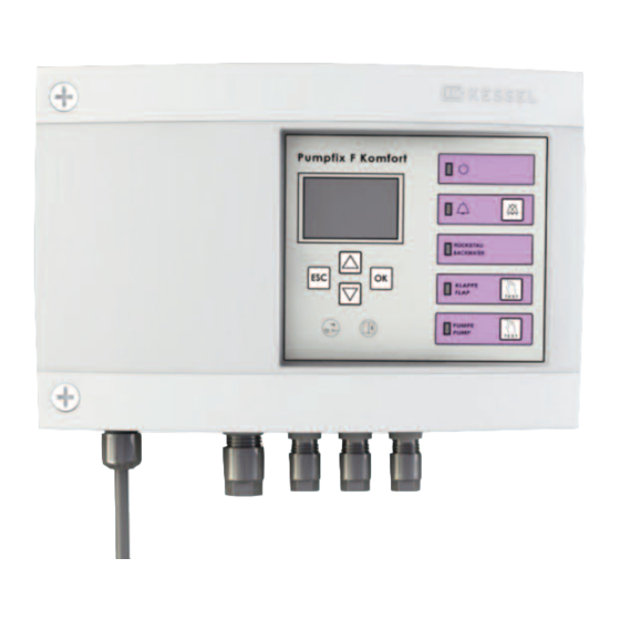
Kessel Pumpfix F Comfort Instructions For Assembly, Operation And Maintenance
Control unit/electric components for backwater pumping station for wastewater containing sewage
Hide thumbs
Also See for Pumpfix F Comfort:
- Manual (132 pages) ,
- Instructions for assembly, operation and maintenance (72 pages) ,
- Nstructions for assembly, operation and maintenance (16 pages)
Table of Contents
Advertisement
Available languages
Available languages
Quick Links
ANLEITUNG FÜR EINBAU, BEDIENUNG UND WARTUNG
Schaltgerät/Elektrokomponenten für KESSEL -
Fäkalien-Rückstaupumpanlage Pumpfix F Komfort
Installation
der Anlage wurde durchgeführt von Ihrem Fachbetrieb:
Name/Unterschrift
Stand 10/2013
Inbetriebnahme
Datum
Einweisung
Ort
D
Seite
GB
Page
I
Pag.
F
Page
PL
NL
Produktvorteile
Schaltgerät Spritzwassergeschützt
IP 54
Steckeranschlüsse für
einfachste Montage
Kein Öffnen zur Installation
erforderlich
Kein Öffnen für die Wandmontage
erforderlich
Komfort Schaltgerät mit
Displayanzeige und
motorischer Rückschlagklappe
Stempel Fachbetrieb
Techn. Änderungen vorbehalten
1-20
21-40
41-60
61-80
Sach-Nr. 010-846
Advertisement
Chapters
Table of Contents

Related Manuals for Kessel Pumpfix F Comfort


Summary of Contents for Kessel Pumpfix F Comfort
- Page 1 ANLEITUNG FÜR EINBAU, BEDIENUNG UND WARTUNG Schaltgerät/Elektrokomponenten für KESSEL - Fäkalien-Rückstaupumpanlage Pumpfix F Komfort Seite 1-20 Page 21-40 Pag. 41-60 Page 61-80 Produktvorteile Schaltgerät Spritzwassergeschützt IP 54 Steckeranschlüsse für einfachste Montage Kein Öffnen zur Installation erforderlich Kein Öffnen für die Wandmontage erforderlich Komfort Schaltgerät mit...
-
Page 2: Table Of Contents
Inhaltsverzeichnis ......................Seite Sicherheitshinweise ......................Seite 1. Allgemein Wandmontage des Schaltgerätes ............Seite Kabelanschluss.................. Seite 2. Elektroanschluss Sonden-/Motormontage ..............Seite Externer Signalgeber ................. Seite Potentialfreier Kontakt................ Seite Pumpenanschluss................Seite Verlängerung der Steuerleitungen ............. Seite Anschlusssplan Schaltgerät .............. Seite Schaltgerät....................Seite Prüfung Komfort................. -
Page 3: Sicherheitshinweise
1. Allgemein Sehr geehrter Kunde, wir freuen uns, dass Sie sich für ein Produkt von KESSEL entschieden haben. Die gesamte Anlage wurde vor Verlassen des Werkes einer strengen Qualitätskontrolle unterzogen. Prüfen Sie bitte dennoch so - fort, ob die Anlage vollständig und unbeschädigt bei Ihnen angeliefert wurde. Im Falle eines Transportschadens beachten Sie bitte die Anweisung in Kapitel „Gewährleistung“... -
Page 4: Elektroanschluss
2. Elektroanschluss 2.1 Wandmontage des Schaltgerätes 2.3 Sonden-/Motormontage Die optische Son de für die Pumpe (rot) Sonde: wird im Deckel an der Zulaufseite mon- Das Schaltgerät muss trocken und tiert. Dazu wird der Blindstopfen (lila) ent- frostsicher installiert werden, vorzugs- fernt und die Sonde mit beiliegenden weise im Haus, wo etwaige Alarmmel- Schrau ben handfest angeschraubt (2... - Page 5 2. Elektroanschluss 2.8. Anschlussplan Schaltgerät Komfort...
-
Page 6: Inbetriebnahme Komfort
3. Inbetriebnahme Komfort 3.1 Schaltgerät Zur Inbetriebnahme muss das Schalt- gerät nicht mehr geöffnet werden. Die im Lieferumfang enthaltenen Batteri- en sind bereits angeschlossen und wer- den beim ersten 230V-Netzanschluss ak- tiviert. Die Netzleitung anschließen. Das Schaltgerät führt einen Grundfunk - tionstest, die sog. -
Page 7: Betrieb Komfort Schaltgerät
4. Betrieb Komfort Schaltgerät 4.1 Betriebsfälle Diodenanzeige Netzbetrieb Batteriebetrieb grün leuchtet blinkt (1 sec. Takt) Betriebsbereitschaft Power-LED Alarm-LED Klappe schließt Power-LED grün leuchtet Alarm-LED Rückstau Rückstau-LED orange blinkt Klappe-LED orange blinkt blinkt (1 sec. Takt) Pumpe-LED orange Klappe ist geschlossen Power-LED grün leuchtet Alarm-LED... - Page 8 4. Betrieb Komfort Schaltgerät 4.4 Displayanzeigen 4.4.1 Erstinbetriebnahme b) Mit den Pfeiltasten “Tag” ein- a) Bei Erstinbetriebnahme er- stellen, mit der OK-Taste be- scheint Bild 3.5.1. Mit den stätigen. Der Cursor springt Pfeiltasten wählen Sie die zum Feld “Monat”. Diese entsprechende Menüspra- und weitere Einstellungen che, mit der OK-Taste be-...
- Page 9 4. Betrieb Komfort Schaltgerät Displayanzeige Beschreibung Information 4.4.3 Menüerklärung Bildschirmanzeige im Beim Drücken einer Displaymenütaste Betriebszustand schaltet sich die Displaybeleuchtung ein Das Menü besteht aus 1. Information 3 Hauptmenüpunkten 2. Wartung 3. Einstellungen Der Hauptmenüpunkt Information 1.1 Betriebsstunden besteht aus 5 Untermenüpunkten. 1.2 Logbuch Hier können Werte abgefragt, jedoch 1.3 Steuerungstyp...
- Page 10 4. Betrieb Komfort Schaltgerät Displayanzeige Beschreibung Information Alle Klappenschaltspiele werden Summe aller Schließvorgänge angezeigt Alle Pumpenschaltspiele werden an- Summe aller Pumpenanläufe gezeigt Alle Netzausfälle seit Summe aller Netzausfälle Inbetriebnahme werden angezeigt Im Logbuch sind die letzten Ereignis- 255 Einträge werden gespeichert. Darüber- se und Fehlermeldungen gespei- hinaus wird immer der älteste überschrieben.
- Page 11 4. Betrieb Komfort Schaltgerät Displayanzeige Beschreibung Information Es werden 15 Parameter angezeigt 1.5.1 Netz Ein. Verz. 1.5.9 Betriebsmodus 1.5.2 Einschaltsper. 1.5.10 Einsch.Verz.2 1.5.3 Einsch. Verz. 1 1.5.11 Nachlaufzeit 2 1.5.4 Nachlaufzeit 1 1.5.12 Max. Zyklen.PU 1.5.5 Max. Zyklen Klappe 1 1.5.13 Max.
- Page 12 Defaultwert ist 30. Motorklappenschliessungen in einem bestimmten Zeitraum wird angezeigt. Der Zeitraum zwischen zwei Selbst- Defaultwert sind 28 Tage. diagnosetests (SDS) wird angezeigt. Diese Information dient KESSEL-Kunden- dienstpartnern. Die Einschaltverzögerung der Pumpe wird angezeigt. Die Nachlaufzeit der Pumpe wird angezeigt.
- Page 13 3.1, 3.2, 3.4, 3.6 sind passwort- Hier können Einstellungen vorgenommen geschützt. werden. Der Zugang der passwortgeschützten Im restlichen Bereich können Werte Untermenüs ist nur KESSEL-Kundendienst- geändert werden. partnern möglich. Hier können Datum und Uhrzeit ein- Siehe 7.4.1 Erstinbetriebnahme gestellt wertden.
-
Page 14: Fehlererkennung Komfort
5. Fehlererkennung Komfort Schaltgerät Mit dem KESSEL-Schaltgerät können Fehler bei der Inbetriebnahme sowie während des Betriebs erkannt und somit leicht abgestellt werden. 5.1 Störungen bei Netzbetrieb ➤ Diodenanzeige Fehleranzeige Ursache Abstellmaßnahme Hinweise Power-LED blinkt, Batterie fehlt oder ist defekt Netzstecker... - Page 15 5. Fehlererkennung Komfort Schaltgerät Fehleranzeige Ursache Abstellmaßnahme Hinweise Max. Zyklenzahl Pumpe tauschen Lebensdauer Pumpe erreicht Power-LED leuchtet Alarm-LED blinkt Pumpe überschritten abwechselnd mit Pumpe-LED Power-LED leuchtet Grenzlaufzahl Pumpe Kundendienstpartner Pumpe läuft zu oft an in kurzer Alarm-LED blinkt überschritten informieren Zeit gleichzeitig mit Pumpe-LED...
- Page 16 5. Fehlererkennung Komfort Schaltgerät Displayanzeige Ursache Abstellmaßnahme Hinweise Netzstecker ziehen, Batterie de- Die Abfrage der Sondenleitung erfolgt Steuerleitung „Pumpen- aktivieren; Steuerleitung auf kor- alle 2 sec. - Initialisierung: Sonde“ nicht ange- rekten Anschluß, bzw. Durch- schlossen, verpolt oder gang kontrollieren; ggf. Pum- gebrochen pen-Sonde austauschen.
- Page 17 5. Fehlererkennung Komfort Schaltgerät 5.3 Störungen bei Batteriebetrieb / Netzausfall ➤ Diodenanzeige Fehleranzeige Ursache Abstellmaßnahme Hinweise Gerät ist im Batteriebetrieb; Netzspannung kontrollieren, ggf. Die Anlage ist 2 Stunden funktions- Alarm-LED blinkt Netzspannung fehlt wiederherstellen fähig. Anschließend geht das Gerät schnell in den Sleep-Modus (siehe Kap.
-
Page 18: Zusatzfunktionen
6. Zusatzfunktionen 6.1 Potentialfreier Alarmausgang 6.3 Sleep-Modus 6.5 Kontrolle der Batteriespannung Das KESSEL-Schaltgerät für den Pumpfix Befindet sich die Steuerung länger als 2 Stun - Die Steuerung überprüft konstant die Bat- ® F kann mit einem Anschluss für einen po- den im Batteriebetrieb, geht sie in einen sog. -
Page 19: Inspektion Und Wartung
1. Ist eine Lieferung oder Leistung mangel- Es wird nur für neu hergestellte Sachen Voraussetzung hierfür ist eine fachmänni- haft, so hat KESSEL nach Ihrer Wahl den eine Gewährleistung übernommen. sche Montage sowie ein bestimmungs- Mangel durch Nachbesserung zu beseiti- Die Gewährleistungsfrist beträgt 24 Mona-... - Page 20 Führend in Entwässerung Privater Wohnungsbau ohne Kanalanbindung 1 2 3 4 1 2 3 4 Öffentlicher Bau z.B. Krankenhaus Öffentlicher Bau z.B. Freizeitanlagen 1 2 3 4 Gewerblicher Bau z.B. Hotel Gewerblicher Bau z.B. Industriebau 2 3 5 Gewerblicher Bau z.B.
- Page 21 INSTRUCTIONS FOR ASSEMBLY, OPERATION AND MAINTENANCE Control unit/electric components for KESSEL backwater pumping station for wastewater containing sewage Pumpfix F Comfort Product advantages Control unit splashwater-proof IP 54 Plug connections for very straight- forward installation Does not have to be opened for in-...
- Page 22 Table of contents ......................Page Safety instructions ......................Page 1. General Mounting the control unit on the wall..........Page Cable connection ................Page 2. Electrical connection Probe/motor installation ..............Page External signal generator ..............Page Potential-free switch contact .............. Page Pump connection ................
-
Page 23: Safety Instructions
Prior to carrying out any work on the system, the operator and the responsible technical per- sonnel must carefully read and heed these installation and operating instructions. The installation of the KESSEL automatic backwater valve for wastewater with sewage Pumpfix F is described in the separate in- ®... -
Page 24: Electrical Connection
2. Electrical connection 2.1 Mounting the control unit on the 2.3 Probe/motor installation Probe: wall The optical probe for the pump (red) is mo- unted in the cover on the inlet side. For this The control unit must be installed dry purpose, the blind plug (lilac) is removed and frostproof, preferably in the house, and the probe is screwed in place hand-tight... - Page 25 2. Electrical connection 2.8. Connection diagram Comfort control unit...
-
Page 26: Putting The Comfort
3. Putting the Comfort unit into operation 3.1 Control unit The control unit does not have to be opened for initial operation. The batteries included in the scope of sup- ply are already connected and are activa- ted the first time the unit is connected to the 230V mains supply. -
Page 27: Operating The Comfort Control Unit
4. Operating the Comfort control unit 4.1 Working conditions diode display Power mode Battery mode green flashing (1 sec. Takt) Readiness for operation Power-LED Alarm-LED Flap closes Power-LED green Alarm-LED Backwater Backwater-LED orange flashing Flap-LED orange flashing flashing (1 sec. Takt) Pump-LED orange Flap is closed... -
Page 28: Displays
4. Operating the Comfort control unit 4.4 Displays 4.4.1 Initial operation a) Fig. 3.5.1 appears during in- b) Use the arrow keys to set itial operation. Use the the “day”, confirm using the arrow keys to select the res- OK key. The cursor will pective menu language, move to the “month”... -
Page 29: Explanation Of Menu
4. Operating the Comfort control unit Display Description Information 4.4.3 Explanation of menu Monitor display during operating When a display menu key is pressed, the dis- state play lighting is switched on The menu comprises 3 main menu 1. Information items 2. - Page 30 4. Operating the Comfort control unit Display Description Information All flap switching cycles are display- Sum of all closing procedures All pump switching cycles are dis- Sum of all pump power-ups played All power failures since initial operati- Sum of all power failures on are displayed.
- Page 31 4. Operating the Comfort control unit Display Description Information It shows 15 Parameters 1.5.1 Mains switch-on delay 1.5.9 Operating mode 1.5.2 Switch-on block 1.5.10 Switch-on delay 2 1.5.3 Switch-on delay 1 1.5.11 Run-on time 2 1.5.4 Run-on time 1 1.5.12 Max. cycles PU 1.5.5 Max.
- Page 32 The period between two self-diagno- Default value is 28 days. sis tests (SDS) is displayed. This information is for KESSEL customer ser- vice partners. The power-up delay of the pump is displayed. The run-on time of the pump is dis- played.
- Page 33 Remedy measures: the pump is indicated. - Clean the probe - Clean the pump The main menu item “Maintenance” Access is only possible for KESSEL customer is password-protected. Values can service partners. be changed here. 3.3 Date/time The main menu item “Settings” is 3.5 Language...
-
Page 34: Problems With Mains Operation/Diode Display
5. Fault detection Komfort control unit The KESSEL control unit detects faults during start-up and during operation, allowing them to be remedied easily. 5.1 Problems with mains operation / diode display Fault display Cause Remedy Notes Power-LED flashing, Battery is missing or faulty... -
Page 35: Problems With Mains Operation/Display
5. Fault detection Komfort control unit Fehleranzeige Ursache Remedy Notes Max. number of cycles Replace the pump Pump service life reached Power-LED lit Alarm LED flashing for pump exceeded alternating with flap-LED Running time limit for pump Power-LED lit Inform the customer Pump starts up too often at short exceeded Alarm LED flashing... - Page 36 5. Fault detection Komfort control unit Display Cause Remedy Notes - Initialisation: “Pump Remove the mains plug, deac- The probe is scanned every 2 se- probe” control cable is tivate the battery; check the conds. not connected, connec- control cable for correct ted with inverse polarity connection or passage, replace or is broken...
-
Page 37: Problems With Battery Operation/Power Failure - Diode Display
5. Fault detection Komfort control unit 5.3 Problems with battery operation / power failure / diode display Display Cause Remedy Notes Device is in battery operati- Check mains voltage and set up The system is functional for 2 hours. Alarm LED flashing on;... -
Page 39: Service
Repairs may only be carried out by the manufacturer. 9. Warranty 1. In the case that a KESSEL product is de- or part needing repair or replacement and and operated in accordance with the valid fective, KESSEL has the option of repai-... - Page 40 Leading in Drainage Private homes without public sewage connection 1 2 3 4 1 2 3 4 Public buildings e.g. hospital) Public buildings e.g. leisure facility) 1 2 3 4 Commercial buildings e.g. hotel) Commercial buildings e.g. industrial / manu- facturing facilities) 2 3 5 Commercial buildings...
- Page 41 ISTRUZIONI PER IL MONTAGGIO, L’USO E LA MANUTENZIONE Centralina/Componenti elettrici per l’impianto di pompaggio delle acque di riflusso con sostanze fecali Pumpfix F Comfort KESSEL Vantaggi del prodotto Centralina protetta dagli spruzzi d’acqua IP 54 collegamenti a spina per un montaggio estremamente facile Non occorre aprire per l’installazione...
- Page 42 Indice ......................Pagina Avvertenze sulla sicurezza ......................Pagina 1. In generale Montaggio a parete della centralina ........... Pagina Collegamento dei cavi................ Pagina 2. Allacciamento elettrico Montaggio sonda/motore ..............Pagina Trasduttore di segnali esterno ............Pagina Contatto a potenziale zero ..............Pagina Collegamento della pompa ............
-
Page 43: Avvertenze Sulla Sicurezza
In caso di interventi sull’impianto, l’utente e il personale specializzato addetto devono legge- re e seguire scrupolosamente queste istruzioni per il montaggio e l’uso. Il montaggio e l’installazione dell’impianto automatico antiriflusso per sostanze fecali Pumpfix® F KESSEL vengono descritti nelle relative istruzioni separate (010-843) fornite. -
Page 44: Allacciamento Elettrico
2. Allacciamento elettrico 2.3 Montaggio sonda/motore rosso 2.1 Montaggio a parete della centrali- Sonda: La sonda ottica per la pompa (rossa) viene La centralina deve essere installata in montata nel coperchio sul lato alimenta- un luogo asciutto e protetto dal gelo, zione. - Page 45 2. Allacciamento elettrico 2.8. Schema degli allacciamenti centralina Comfort Rete Pompa Sonde ottica servomotore Sonde ottica Trasduttore Contatto a potenziale rossa nera di segnale...
-
Page 46: Messa In Funzione Comfort
3. Messa in funzione Comfort 3.1 Centralina La centralina non deve più essere aper- ta per la messa in funzione. Le batterie comprese nel volume della for- nitura sono già collegate e vengono atti- vate all’atto del primo allacciamento alla rete da 230V. -
Page 47: Funzionamento Centralina Comfort
4. Funzionamento centralina Comfort 4.1 Casi d’esercizio indicazione a diodi Netzbetrieb Batteriebetrieb verde illuminato spento rosso spento Lampeggiante (1 sec.) Disponibilità al funzionamento Power-LED Allarme-LED La valvola chiude Power-LED verde lilluminato spento rosso spento spento Riflusso Riflussso-LED orange Lampeggiante spento Allarme-LED Flap-LED orange... - Page 48 4. Funzionamento centralina Comfort 4.4 Indicazioni sul display 4.4.1 Prima messa in funzione a) Alla prima messa in funzio- b) Con i tasti freccia impostare ne appare l’immagine 3.5.1. “Giorno”, confermare con il Con i tasti freccia si selezio- tasto OK. Il cursore passa al na la relativa lingua del campo “Mese”.
- Page 49 4. Funzionamento centralina Comfort Indicazione sul menu Descrizione Informazioni 4.4.3 Spiegazione del menu Indicazione sullo schermo in condi- Premendo un tasto del menu del display, si zioni di funzionamento accende l’illuminazione del display Il menu è composto da 1. Informazioni 3 punti del menu principale 2.
- Page 50 4. Funzionamento centralina Comfort Indicazione sul menu Descrizione Informazioni Vengono visualizzati tutti i cicli di Vengono memorizzate 255 registrazioni. Oltre commutazione della valvola a questo numero, la più vecchia viene so- vrascritta Vengono visualizzati tutti i cicli di Totale di tutti gli avvii della pompa commutazione della pompa Vengono visualizzate tutte le interru- Totale di tutte le interruzioni dell’energia elettri-...
- Page 51 4. Funzionamento centralina Comfort Indicazione sul menu Descrizione Informazioni Esso visualizza 15 parametri 1.5.1 Rit. inserz. rete 1.5.9 Modo operativo 1.5.2 Blocco inserz. 1.5.10 Rit. inserz. 2 1.5.3 Rit. inserz. 1 1.5.11 Tempo di coda 2 1.5.4 Tempo di coda 1 1.5.12 Cicli max.
- Page 52 Viene visualizzato il lasso di tempo Valore default 28 giorni tra due test di autodiagnosi (SDS) Questa informazione serve ai partner del ser- vizio assistenza KESSEL Viene visualizzato il ritardo d’inser- zione della pompa. Viene visualizzato il tempo di coda della pompa.
- Page 53 - pulire la pompa Il punto del menu principale Manu- L’accesso è possibile solo ai partner del servi- tenzione è protetto da una password. zio assistenza KESSEL. Qui è possibile modificare valori. 3.3 Data / Ora Il punto del menu principale “Im- 3.5 Lingua...
- Page 54 5. Riconoscimento errori centralina Comfort Con la centralina KESSEL si possono riconoscere e quindi eliminare facilmente errori sia all’atto della messa in funzione sia durante il funzionamento. 5.1 Anomalie durante il funzionamento a rete / indicazione a diodi. Segnalazione Inizializzazione: l’impianto può esse-...
- Page 55 5. Riconoscimento errori centralina Comfort Fehleranzeige Ursache Abstellmaßnahme Hinweise Power-LED illumina Numero max. di cicli della Sostituire la pompa Durata operativa della pompa rag- LED-allarme lampeg- pompa superato giunta gia in alternanza con il LED della pompa La pompa si avvia toppo spesso in breve tempo IPower-LED illumina Numero max.
- Page 56 5. Riconoscimento errori centralina Comfort Visualizzare Causa Rimedio Indicazioni Inizializzazione: linea di Staccare la spina, disattivare la L’interrogazione della linea della controllo “Sonda pompa” batteria; controllare se la linea sonda avviene ogni 2 sec. non collegata, interrotta di controllo è collegata corretta- o polarità...
- Page 57 5. Riconoscimento errori centralina Comfort 5.3 Anomalie durante il funzionamento a batteria / interruzione di energia elettrica / indicazione a diodi Segnalazione anomalie Causa Rimedio Indicazioni Il LED di allarme L’apparecchio è nel funzio- Controllare la tensione di rete, L’impianto può funzionare per 2 ore. lampeggia veloce- namento a batteria;...
-
Page 58: Funzioni Addizionali
è chiusa), ogni 20 sec. viene emesso allarme ottico e acustico finché la batteria è 6.1 Output di allarme a potenziale zero 6.5 Controllo della tensione della bat- La centralina KESSEL per il Pumpfix® F può scarica. Contemporaneamente, l’allarme Il comando controlla costantemente la teria... -
Page 59: Ispezione E Manutenzione
2. La ditta KESSEL non riconosce l`usura razione del bene contestato ovvero novo. La garanzia ha una validità di 24 come un difetto o un malfunzio- alla sua sostituzione. - Page 60 Leader del drenaggio Edilizia residenziale privata senza collegamento alla fogna 1 2 3 4 1 2 3 4 Edilizia pubblica per es Ospedale Edilizia pubblica per es Impianti ricreativi 1 2 3 4 Edilizia commerciale per es Albergo Edilizia commerciale per es Capannoni 2 3 5 Edilizia commerciale...
- Page 61 INSTRUCTIONS DE MONTAGE, DE COMMANDE ET DE MAINTENANCE Boîtier de commande/composants électriques du poste automatique de pompage anti-retour des eaux usées et eaux-vannes KESSEL Pumpfix F Komfort Avantages du produit boîtier de commande protégé contre les projections d'eau IP 54 montage très facile grâce aux rac-...
- Page 62 Sommaire ......................Page Consignes de sécurité ......................Page 1. En général Montage mural du boîtier de commande ........... Page Raccordement des câbles ..............Page 2. Raccordement électrique Montage des sondes / du moteur............Page Alarme externe................... Page Contact sans potentiel ............... Page Raccordement de la pompe...............
-
Page 63: Consignes De Sécurité
Le montage et l'installation du poste automatique de pompage anti-retour des eaux usées et eaux-vannes KESSEL Pumpfix® F sont décrits dans des instructions de montage fournies séparément (010-843). -
Page 64: Raccordement Électrique
2. Raccordement électrique 2.1 Montage mural du boîtier de com- 2.3 Montage des sondes / du moteur- mande Sonde: La sonde optique pour la pompe La pose du boîtier de commande doit se (rouge) se monte dans le couvercle côté faire au sec et à... - Page 65 2. Raccordement électrique 2.8 Schéma de raccordement du boîtier de commande version Confort...
-
Page 66: Mise En Service De La Version Confort
Le poste automatique de c) Ligne de raccordement au réseau l) Raccord de la pompe pompage des eaux de reflux KESSEL d) DEL verte « Puissance » m) Raccord de la sonde de la pompe Pumpfix® F est prêt au service mainten- e) DEL rouge «... -
Page 67: Fonctionnement Du Boîtier De Commande Version Confort
4. Fonctionnement du boîtier de commande version Confort 4.1 Cas se produisant en exploitation Diodes d'affichage Netzbetrieb Batteriebetrieb verte brille éteinte éteinte clignote (1 sec. Takt) Disponibilité au service Power-DEL Alarm-DEL Le clapet ferme Power-DEL verte brille éteinte Alarm-DEL rouge éteinte Reflux Reflux-DEL... - Page 68 4. Fonctionnement du boîtier de commande version Confort 4.4 Affichages b) Servez-vous des touches 4.4.1 Première mise en service a)L'écran 3.5.1 s'affiche lors fléchées pour paramétrer la « de la première mise en servi- date » ; validez en appuyant ce.
- Page 69 4. Fonctionnement du boîtier de commande version Confort Affichage de l'écran Description Information 4.4.3 Menu Affichages en état de service L'éclairage de l'écran s'affiche en appuyant sur une touche de menu. Le menu est composé de 3 points de 1. Information menu principaux 2.
- Page 70 4. Fonctionnement du boîtier de commande version Confort Affichage de l'écran Description Information Affichage de tous les cycles de Total de toutes les fermetures manœuvre du clapet Affichage de tous les cycles de Total de tous les démarrages de la pompe manœuvre de la pompe Total de tous les démarrages de la Total de toutes les pannes de secteur...
- Page 71 4. Fonctionnement du boîtier de commande version Confort Affichage de l'écran Description Information Il est indiqué paramètres 15 1.5.1 Mise en service du réseau 1.5.10 Mise en service temporisée 2 temporisée 1.5.11 Marche par inertie 2 1.5.2 Blocage de mise en service 1.5.12 Nombre de cycles max.
- Page 72 Affichage de la période écoulée Valeur par défaut de 28 jours. entre deux autodiagnostics (SDS). Cette information est destinée aux partenaires du service après-vente de KESSEL. Affichage de la temporisation de mise en circuit de la pompe. Affichage de la marche par inertie de la pompe..
- Page 73 Le point de menu principal <Mainten- L'accès à ce menu est réservé aux partenai- ance> est protégé par des mots de res du service après-vente de KESSEL de ce passe. Ce menu permet de modifier fait. les valeurs assignées au boîtier.
- Page 74 5. Détection des erreurs du boîtier de commande Confort Le boîtier de commande KESSEL permet de détecter les erreurs lors de la mise en service et en cours d'exploitation et de les élimi- ner facilement de ce fait. 5.1 Pannes en exploitation sur secteur ➤ diodes d'affichage Erreur affichée...
- Page 75 5. Détection des erreurs du boîtier de commande Confort Erreur affichée Cause Remède Observations DEL puissance brille Dépassement du nombre Remplacez la pompe Atteinte de la durée de vie utile de DEL d'alarme clignote maximal de cycles de la la pompe en alternance avec la pompe DEL de la pompe...
- Page 76 5. Détection des erreurs du boîtier de commande Confort Erreur affichée Cause Remède Observations En phase d’initialisation : Retirez la fiche de la prise au L'interrogation des deux sondes ligne pilote de la « sonde secteur, désactivez la batterie ; s'opère toutes les 2 secondes..
- Page 77 5. Détection des erreurs du boîtier de commande Confort 5.3 Pannes en alimentation par batterie / panne de secteur ➤ diodes d'affichage Erreur affichée Cause Remède Observations Boîtier est en alimentation DEL d'alarme cligno- Contrôlez la tension de réseau, Le poste fonctionne durant 2 heu- par batterie ;...
-
Page 78: Fonctions Supplémentaires
Les piles ci-après sont homologuées pour le les éliminer en suivant les informations au Pumpfix® F de KESSEL : Duracell : Taille 9V .6.4 Panne de secteur Chapitre 5. ; type MN 1604/6LR61 (Réf. 197-081 ; quan- tité... -
Page 79: Inspection Et Maintenance
9. arantie 1. Si une livraison ou une prestation est dé- Une garantie ne peut être transmise 2. KESSEL rappelle que l'usure n'est pas un fectueuse, KESSELs’engage, selon votre qu’aux objets nouvellement fabriqués. La défaut pris en compte par la garantie. Il en choix, à... - Page 80 Leader en solution d’assainissement Construction de logements privés sans raccordement au réseau d’assainissement public 1 2 3 4 1 2 3 4 Construction de logements Construction publique, par privés sans raccordement au exemple aménagement de loisirs réseau d’assainissement public 1 2 3 4 Construction industrielle 2 3 5...
- Page 81 InstrUKcja zabUdowy, obsłUgI I KonserwacjI Urządzenie sterownicze / komponenety elektryczne do zaworu zwrotnego z pompą Pumpfix F Komfort do ścieków zawierających fekalia Zalety produktu Urządzenie sterownicze z ochroną przeciwbryzgową IP 54 Przył ącza wtykowe gwarantujące niezwykle ł atwy montaż Brak koniecznoś ci otwierania w celu instalacji Brak koniecznoś...
- Page 82 spis treści Wskazówki dotyczące bezpieczeństwa ..........................strona 83 1. Informacje ogólne ..........................strona 83 2. Podł ączenie do instalacji elektrycznej Montaż urządzenia sterowniczego na ś cianie ............strona 84 Podł ączenie kabla ....................strona 84 2.2.1 Standard........................strona 84 2.2.2 Komfort........................strona 84 Montaż...
- Page 83 wskazówki bezpieczeństwa Personel montażowy, obsł ugujący, przestrzegać instrukcji obsł ugi cał ej autoryzowane przez producenta zapewniają wykonujący prace konserwacyjne i naprawcze instalacji oraz poszczególnych bezpieczeństwo. Stosowanie innych częś ci musi dysponować odpowiednimi kwalifikacjami komponentów. Podczas montażu, konserwacji, wyklucza odpowiedzialnoś ć za powstał e w do wykonywania tych prac.
- Page 84 2. Podłączenie do instalacji elektrycznej 2.1 Montaż urządzenia sterowniczego na 2.3 Montaż sondy/silnika czerwony ścianie Sonda: Sonda optyczna pompy (czerwona) montowana Szafka sterownicza musi zostać jest w pokrywie po stronie dopł ywu. W tym zainstalowana miejscu suchym celu usuwa się zaś lepki (w kolorze lila) i ręcznie zabezpieczonym przed mrozem, najlepiej w mocuje się...
- Page 85 2. Podłączenie do instalacji elektrycznej 2.8 Schemat podł ączenia urządzenia sterowniczego Komfort Pompa Sonda optyczna Silnik Sonda optyczna Podajnik Kontakt Sieć czerwona carna sygnał u bezpotencjał owy...
- Page 86 3. Uruchomienie Komfort 3.1 Urządzenie sterujące Urządzenia sterowniczego nie trzeba otwierać w celu uruchomienia. Baterie wchodzące w skł ad komletu są już zał ożone i są aktywowane przy pierwszym podł ączeniu do sieci 230 V. Następnie podł ączyć przewód sieciowy. Urządzenie sterownicze przeprowadza test...
- Page 87 4. Praca urządzenia sterowniczego Komfort 4.1 Sytuacje robocze wskazania diodowe Tryb zasilania sieciowego Zasilanie bateryjne Gotowość do pracy LED Power zielony ś wieci wył ącz. LED Alarm czerwony wył ącz. miga (co 1 sek.) Przepł yw zwrotny Klapa zamyka się LED Power zielony ś...
- Page 88 4. Praca urządzenia sterowniczego Komfort 4.4 Wskazania wyświetlacza 4.4.1 Pierwsze uruchomeinie b) Za pomocą przycisków strzał ki a) Przy pierwszym uruchomieniu ustawić “Dzień”, potwierdzić pokazuje się okno 3.5.1. Za przciskiem OK. Kursor pomocą przycisków strzał ek przeskakuje na “Miesiąc”. wybrać odpowiedni język menu, Następne ustawienia wykonuje się...
- Page 89 4. Praca urządzenia sterowniczego Komfort 4.4.3 Objaśnienie elementów menu Wyświetlacz Opis Informacja Wskazanie na ekranie w Przy wciś nięciu przycisku menu wyś wietlacza trybie pracy wł ącza się podś wietlenie wyś wietlacza Menu skł ada się z 1. Informacja 3 gł ównych punktów 2.
- Page 90 4. Praca urządzenia sterowniczego Komfort Wyświetlacz Opis Informacja Pokazywane są wszystkie przeł ączenia Suma wszystkich zamykań klapy Pokazywane są wszystkie przeł ączenia pompy Suma wszystkich rozruchów pompy Pokazywane są wszystkie braki prądu Suma wszystkich braków prądu od uruchomienia W dzienniku są zapisane ostatnie wydarzenia i 255 wpisów w pamięci.
- Page 91 4. Praca urządzenia sterowniczego Komfort Wyświetlacz Opis Informacja Pokazuje się 15 parametrów 1.5.1 Sieć wł ączona opóźn. 1.5.9 Tryb pracy 1.5.2 Blokada wł ączania 1.5.10 Opóźn. wł ącz.2 1.5.3 Opóźn. wł acz. 1 1.5.11 Czas wybiegu 2 1.5.4 Czas wybiegu 1 1.5.12 Maksymalne cykle PU 1.5.5 Maxks.
- Page 92 Pokazywany jest okres czasu pomiędzy dwoma Wartoś ć domyś lna 28 dni. testami samodiagnozy (SDS). Ta informacja przeznaczona jest dla serwisantów KESSEL. Pokazywane jest opóźnienie wł ączania pompy. Pokazywany jest czas wybiegu pompy.
- Page 93 Tutaj można wprowadzać ustawienia. Dostęp do podmenu W pozostał ym zakresie można zmieniać chronionych hasł em możliwy tylko dla partnerów wartoś ci. serwisowych KESSEL. Tutaj można ustawić datę i godzinę. Patrz 7.4.1 Pierwsze uruchomeinie Tutaj można wybrać język menu. Patrz 7.4.1 Pierwsze uruchomeinie Tutaj można wybrać...
- Page 94 5. rozpoznawanie błędów urządzenie sterownicze Komfort Za pomocą urządzenia przeł ączającego KESSEL można rozpoznać i usunąć awarie przy uruchomieniu i podczas pracy urządzenia. 5.1 Zakł ócenia w przypadku zasilania sieciowego wskazania diodowe Wyświetlanie bł ędu: Przyczyna Dział anie Wskazówki - Inicjalizacja: Urządzenia nie można...
- Page 95 5. rozpoznawanie błędów urządzenie sterownicze Komfort Wyświetlanie bł ędu: Przyczyna Dział anie Wskazówki LED Power ś wieci Maks. liczba cykli Wymienić pompę Okres żywotnoś ci pompy skończył się LED Alarm miga pompy przekroczona na zmianę z LED Pompa LED Power ś wieci Graniczny czas pracy pompy Skontaktować...
- Page 96 5. rozpoznawanie błędów urządzenie sterownicze Komfort Wyświetlacz Przyczyna Dział anie Wskazówki - Inicjalizacja: Wyciągnąć wtyczkę sieciową, Aktywacja przewodu sondy następuje co 2 Przewód sterowania “sonda dezaktywować baterie; przewód sek. pompy” jest sterowania sprawdzić pod kątem podł ączony, zamieniono prawidł owego przył...
- Page 97 5. rozpoznawanie błędów urządzenie sterownicze Komfort 5.3 Zakł ócenia w wypadku zasilania z baterii / brak prądu wskazania diodowe Wyświetlanie bł ędu: Przyczyna Dział anie Wskazówki Urządzenie jest zasilane z baterii; Skontrolować napięcie sieciowe względnie Urządzenie może dział ać przez 2 godziny. LED Alarm miga szybko brak napięcia w sieci je przywrócić...
- Page 98 Trwał oś ć nowych baterii wynosi min. 2 lata . urządzenia Komfort także klapa, przeprowadza dział ać . Przykł adowo , jeś li sterowanie zostanie Do pracy w urządzeniu KESSEL Pumpfix ® automatyczne sprawdzenie dział ania. W tym zainstalowane podczas fazy budowlanej, ale urządzenie nadają...
- Page 99 • Baterie są elementami eksploatacyjnymi i www.kessel.pl powinny być w miarę możliwoś ci sprawdzane 9. gwarancja ,F30 +69:(8*?656 <(+30<> :6<(8 -084( ,99,3 4( 78(<6 <>)68; 97696); 769:D76<(50( *?> ;9:,82( ?69:(50, ;9;50D:( 5( *?> :,H <(+30<> 786+;2: ?69:(50, <>40,5065>...
- Page 100 Wiodący producent systemów odwadniania Budownictwo mieszkaniowe bez podłączenia do kanalizacji 1 2 3 4 5 1 2 3 4 5 Budynki użyteczności Budowle ogólnodostępne publicznej, np. szpitale np. obiekty rekreacyjne Działalność gospodarcza np. hotele Budownictwo przemysłowe 2 3 5 Budownictwo handlowo-usługowe np.
- Page 101 Gebruiksaanwijzing voor inbouw, bediening en onderhoud Schakelapparaat/elektrische componenten voor KESSEL fecaliënopstuwingspomp Pumpfix F Komfort Productvoordelen Schakelapparaat spatwaterdicht IP 54 Stekkeraansluitingen voor zeer eenvoudige montage Openen voor installatie niet nodig Openen voor wandmontage niet nodig Komfort schakelapparaat met display-indicatie en motorische terugslagklep...
- Page 102 Inhoudsopgave ......................Pagina 103 Veiligheidsinstructies ......................Pagina 103 1. Algemeen 2. Aansluiting op het elektriciteitsnet 2.1 Functie van het schakelapparaat ............Pagina 104 Kabelaansluiting................. Pagina 104 Sonde-/motormontage ............... Pagina 104 Externe signaalsensor ............... Pagina 104 Potentiaalvrij contact................Pagina 104 Pompaansluiting ................Pagina 104 Verlenging van de besturingsleidingen ..........
-
Page 103: Algemeen
1. Algemeen Geachte klant, Wij zijn blij dat u gekozen hebt voor een product van KESSEL. De gehele installatie is aan een strenge kwaliteitscontrole onderworpen voordat zij de fabriek verliet. Controleer toch onmiddellijk a.u.b. of de installatie volledig en onbeschadigd bij u geleverd is. Volg in het geval van transportschade a.u.b. de instructie in ho- ofdstuk „Fabrieksgarantie“... -
Page 104: Aansluiting Op Het Elektriciteitsnet
2. Aansluiting op het elektriciteitsnet rood 2.1 Wandmontage van het schakelap- 2.3 Sonde-/motormontage De optische sonde voor de pomp (rood) paraat Sonde: wordt aan de toevoerkant in het deksel gemonteerd. Daartoe wordt de dopvormi- Het schakelapparaat moet droog en ge bout (lila) verwijderd en de sonde met vorstvrij worden geïnstalleerd, bij vo- bijgevoegde schroeven handvast vastge- orkeur in het huis, waar eventuele... - Page 105 2. Aansluiting op het elektriciteitsnet 2.8. Aansluitschema schakelapparaat Komfort...
-
Page 106: Inbedrijfstelling Komfort
3. Inbedrijfstelling Komfort 3.1 Schakelapparaat Het schakelapparaat hoeft voor de in- bedrijfstelling niet meer te worden ge- opend. De in het leveringsprogramma opgeno- men batterijen zijn al aangesloten en wor- den geactiveerd bij de eerste aansluiting op het 230V-net. De voedingsleiding aansluiten. -
Page 107: Bedrijf Komfort Schakelapparaat
4. Bedrijf Komfort schakelapparaat 4.1 Bedrijfsomstandigheden diode-in-diactie Gebruik van het net Gebruik van de batterij groen brandt rood knippert (1 sec. cyclus) Gereedheid voor bedrijf Power-LED Alarm-LED Klep sluit Power-LED groen brandt Alarm-LED rood Opstuwing Opstuwings-LED oranje knippert Klep-LED oranje knippert knippert (1 sec. - Page 108 4. Bedrijf Komfort schakelapparaat 4.4 Display-indicaties 4.4.1 Eerste inbedrijfstelling b) Met de pijltoetsen “dag” in- a) Bij de eerste inbedrijfstelling stellen, bevestigen met de verschijnt afbeelding 3.5.1. toets OK. De cursor springt Met de pijltoetsen selecteert naar het veld “maand”. Deze u de desbetreffende menu- en overige instellingen ge- taal, met de OK-toets beve-...
- Page 109 4. Bedrijf Komfort schakelapparaat Display-indicatie Omschrijving Informatie 4.4.3 Menutoelichting Beeldschermindicatie in de Bij het indrukken van een displaymenutoets bedrijfstoestand wordt de displayverlichting ingeschakeld Het menu bestaat uit 1. Informatie 3 hoofdmenuonderdelen 2. Onderhoud 3. Instellingen Het hoofdmenuonderdeel Informatie 1.1 Bedrijfsuren bestaat uit 5 submenuonderdelen.
- Page 110 4. Bedrijf Komfort schakelapparaat Display-indicatie Omschrijving Informatie Alle klepschakelspelingen worden Totaal van alle sluitprocessen aangegeven Alle schakelcycli van de pomp wor- Totaal aantal malen dat pomp opstart den aangegeven Totaal van netuitval sinds Totaal aantal malen netuitval inbedrijfstelling wordt aangegeven In het logboek staan de laatste resul- Er worden 255 vermeldingen opgeslagen.
- Page 111 4. Bedrijf Komfort schakelapparaat Display-indicatie Omschrijving Informatie Er worden 15 parameters aangege- 1.5.1 Net Aan. Vert. 1.5.2 Inschakelblok. 1.5.9 Bedrijfsmodus ven. 1.5.3 Insch. vert. 1 1.5.10 Insch.vert.2 1.5.4 Nalooptijd 1 1.5.11 Nalooptijd 2 1.5.5 Max. cycli klep 1 1.5.12 Max. cycli.PO 1.5.6 Max.
- Page 112 Defaultwaarde is 30. motorklepsluitingen in een bepaalde periode wordt aangegeven. De periode tussen twee zelfdiagno- Defaultwaarde is 28 dagen setesten (SDS) wordt aangegeven. Deze informatie dient KESSEL-klantendienst- partners. De inschakelvertraging van de pomp wordt aangegeven. De nalooptijd van de pomp wordt aangegeven.
- Page 113 - Sonde reinigen - Pomp reinigen Het hoofdmenuonderdeel onderhoud De toegang is uitsluitend is wachtwoordbeveiligd. Hier kunnen mogelijk voor KESSEL-klantenservicepart- waarden worden gewijzigd. ners. 3.3 Datum / tijd Het hoofdmenuonderdeel instellin- 3.5 Taal gen bestaat uit zeven submenuon- 3.7 Contrast...
- Page 114 5. Foutopsporing Komfort schakelapparaat Met het KESSEL-schakelapparaat kunnen storingen bij de inbedrijfstelling en tijdens het bedrijf worden herkend en zodoende een- voudig worden uitgeschakeld. 5.1 Storingen bij gebruik van het net ➤ Diode-indicatie Display-indicatie Oorzaak Uitschakelmaatregel Aanwijzingen Power-LED knip- Batterij ontbreekt of is defect...
- Page 115 5. Foutopsporing Komfort schakelapparaat Display-indicatie Oorzaak Uitschakelmaatregel Aanwijzingen Power-LED brandt Max. aantal cycli Pomp vervangen Levensduur pomp bereikt Alarm-LED knippert pomp overschreden afwisselend met pomp-LED Power-LED brandt Limiet looptermijn pomp Klantendienstpartner Pomp start te vaak op in korte tijd. Alarm-LED knippert overschreden informeren gelijktijdig met...
- Page 116 5. Foutopsporing Komfort schakelapparaat Display-indicatie Oorzaak Uitschakelmaatregel Aanwijzingen Netstekker uittrekken, batterij Om de 2 sec. worden gegevens op- B e s t u r i n g s l e i d i n g deactiveren; Besturingsleiding gevraagd bij de sondekabel. - Initialisatie: „pompsonde“...
- Page 117 5. Foutopsporing Komfort schakelapparaat 5.3 Storingen bij bedrijf op batterijen / netuitval ➤ Diode-indicatie Display-indicatie Oorzaak Uitschakelmaatregel Aanwijzingen Apparaat werkt op batterijen; Netspanning controleren, evtl. her- De installatie is 2 uur functioneel. Alarm-LED knip- Netspanning ontbreekt stellen Vervolgens gaat het apparaat over pert snel in de sleep-modus (zie hfdst.
-
Page 118: Extra Functies
6. Extra functies 6.1 Potentiaalvrije alarmuitgang 6.3 Sleep-modus 6.5 Controle van de accuspanning Het KESSEL-schakelapparaat voor de Als de besturing zich langer dan 2 uur in de De besturing controleert constant de bat- Pumpfix F kan van een aansluiting voor een batterijmodus bevindt, gaat zij naar een zgn. -
Page 119: Garantie
De garantietermijn bedraagt 24 maanden mende levering twee maal ontoereikend is vanaf de levering aan onze partner. § 377 2. KESSEL wil met nadruk stellen dat slijtage om het probleem op te lossen of indien het van het Duitse Handelswetboek zijn verder geen tekortkoming van het product is. - Page 120 Toonaangevend in waterafvoertechniek Particuliere woningbouw zonder aansluiting op riool 1 2 3 4 1 2 3 4 Utiliteitsbouw bv ziekenhuis Utiliteitsbouw bv vrijetijdsvoorzieningen 1 2 3 4 Bedrijfsmatige bouw bv hotel Bedrijfsmatige bouw bv industriële bouw 2 3 5 Bedrijfsmatige bouw bv tankstations 1 2 3 4 Particuliere woningbouw...
Need help?
Do you have a question about the Pumpfix F Comfort and is the answer not in the manual?
Questions and answers