Table of Contents
Advertisement
Available languages
Available languages
Quick Links
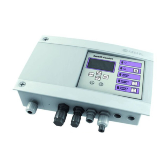
ANLEITUNG FÜR EINBAU, BEDIENUNG UND WARTUNG
KESSEL - Schaltgerät/Elektrokomponenten
für Ecolift
o Installation
der Anlage wurde durchgeführt von ihrem Fachbetrieb:
Name /Unterschrift
Stand 2016/02
o Inbetriebnahme
Datum
o Einweisung
Stempel Fachbetrieb
Ort
Produktvorteile
Spritzwassergeschützt IP 54
Steckeranschlüsse für
einfachste Montage
Kein Öffnen zur Installation
erforderlich
Comfort-Schaltgerät mit
Displayanazeige
Sach-Nr. 010-847
Advertisement
Chapters
Table of Contents

Related Manuals for Kessel Control Unit Ecolift 230V


Summary of Contents for Kessel Control Unit Ecolift 230V
- Page 1 ANLEITUNG FÜR EINBAU, BEDIENUNG UND WARTUNG KESSEL - Schaltgerät/Elektrokomponenten für Ecolift Produktvorteile Spritzwassergeschützt IP 54 Steckeranschlüsse für einfachste Montage Kein Öffnen zur Installation erforderlich Comfort-Schaltgerät mit Displayanazeige o Installation o Inbetriebnahme o Einweisung der Anlage wurde durchgeführt von ihrem Fachbetrieb:...
-
Page 2: Table Of Contents
Allgemeines Einleitung und Begrüßung Produktbeschreibung, allgemein Allgemeine Hinweise zu dieser Betriebs- und Wartungsanleitung 1.3.1 Typenschild Lieferumfang Baugruppen und Funktionselemente 1.5.1 Display und Bedienfeld, Anzeigen Diodenanzeige Schaltgerät Sicherheit Bestimmungsgemäße Verwendung Personalauswahl und -qualifikation Organisatorische Sicherheits-Maßnahmen Gefahren, die vom Produkt ausgehen Gefahr durch elektrischen Strom und Kabel Montage Schaltgerät montieren Abwasserpumpe(n) anschließen... -
Page 3: Allgemeines
ALLGEMEINES Allgemeines 1.1. Einleitung und Begrüßung Sehr geehrte Kundin sehr geehrter Kunde, wir freuen uns, dass Sie sich für den Erwerb eines unserer Produkte entschieden haben. Sicher wird dieses Ihre Anforderungen in vollem Umfang erfüllen. Wir wünschen ihnen einen reibungslosen und erfolgreichen Einbau. Im Bemühen unseren Qualitätsstandard auf höchstmöglichem Niveau zu halten, sind wir natürlich auch auf Ihre Mithilfe angewiesen. -
Page 4: Allgemeine Hinweise Zu Dieser Betriebs- Und Wartungsanleitung
ALLGEMEINES 1.3. Allgemeine Hinweise zu dieser Betriebs- und Wartungsanleitung Verwendete Symbole und Legenden <1> Hinweis im Text auf eine Legendennummer in einer Abbildung Bezug auf eine Abbildung • Arbeitsschritt Aufzählung Kursiv Kursive Schriftdarstellung: Bezug zu einem Abschnitt / Punkt im Steuerungs-Menü VORSICHT: Warnt vor einer Gefährdung von Personen und Material. -
Page 5: Lieferumfang
ALLGEMEINES 1.4. Lieferumfang Betriebs- und Wartungsanleitung Schaltgerät Anschlussplan, im Gehäusedeckel des Schaltgerätes Befestigungsmaterial Bohrschablone 1.5. Baugruppen und Funktionselemente Schaltgerät Kabeldurchführungen, Anschlüsse Display und Bedienfeld 2016/02 5/120... -
Page 6: Display Und Bedienfeld, Anzeigen
ALLGEMEINES 1.5.1 Display und Bedienfeld, Anzeigen Pfeil oben Blättern im Menü Pfeil unten Blättern im Menü Löschen einer Eingabe Bestätigen einer Eingabe Ecolift Betriebsbereit Alarm Alarmtaste Rückstau Testtaste Klappe Klappe Testtaste Pumpe Pumpe 1.6. Diodenanzeige Schaltgerät Netzbetrieb Batteriebetrieb Betriebsbereitschaft Power-LED grün leuchtet Alarm-LED... -
Page 7: Sicherheit
SICHERHEIT Sicherheit 2.1. Bestimmungsgemäße Verwendung Das Schaltgerät Ecolift ist ausschließlich für die Steuerung einer Rückstauhebeanlage zu verwenden. Ein Einsatz des Schaltgeräts in explosionsgefährdeter Umgebung ist unzulässig. Alle nicht durch eine ausdrückliche und schriftliche Freigabe des Herstellers erfolgten - Um- oder Anbauten - Verwendungen von nicht originalen Ersatzteilen Durchführungen von Reparaturen durch nicht vom Hersteller autorisierten Betrieben oder Personen können zum Verlust der Gewährleistung führen. -
Page 8: Montage
MONTAGE Montage 3.1. Schaltgerät montieren • Netzanschluss <41> trennen, und das Gehäuse öffnen, dazu die beiden Schrauben <34> lösen (Linksdrehung) und den Gehäusedeckel aufklappen. • Hinweis: Bohrschablone verwenden/beiliegend. • Gehäuse am vorgesehenen Ort montieren, dazu beide Befestigungsmöglichkeiten verwenden. Im Lieferumfang ist eine Bohrschablone enthalten. -
Page 9: Optische Sonde (Niveaugeber) Anschließen
MONTAGE 3.3. Optische Sonde (Niveaugeber) anschließen Optische Sonde (Niveaugeber) zur Ermittlung des Pegelstandes anschließen. Stecker <42> (Abb. [9]) des Kabels wie in Abb. [10] dargestellt anschließen. Dabei die Mutter mit 1 Nm anziehen. Der Spalt <35> zwischen Mutter und Steckverbindung beträgt dann 1-2 mm (Siehe Abb. [8]) 15mm 19mm = 4mm... -
Page 10: Alarmsonde Anschließen
MONTAGE 3.4. Alarmsonde anschließen Alarmsonde (Motorsonde) zur Ermittlung des Alarm- Pegelstandes anschließen. Stecker <43> des Kabels wie in Abb. [10] dargestellt anschließen. Dabei die Mutter mit 1 Nm anziehen. Der Spalt <35> zwischen Mutter und Steckverbindung beträgt dann 1-2 mm (Siehe Abb. [8]) [10] 3.5. -
Page 11: Funktionskontrolle Der Sonden
• Art der angeschlossenen Sensoren mit den Pfeiltasten auswählen und mit OK bestätigen. • Parameter im Software-Menü 3.1 anpassen. Typ Ecolift Ist die Pumpe der Anlage auf das Schaltgerät abgestimmt (Original KESSEL-Produkte), Einstellung wie bei A) beschrieben vornehmen. • OK betätigen •... -
Page 12: Einstellungen, Menü
MONTAGE 3.6. Einstellungen, Menü Allgemeines Die Menüsteuerung verfügt über einen Bedien- und einen Standbymodus. Im Bedienmodus können die Systemeinstellungen über das Display angezeigt und eingestellt werden (siehe auch 5.2 Menüstruktur). Erfolgt über einen Zeitraum von ca. 60 Sekunden keine Betätigung einer der Tasten, wird automatisch der Stand- bymodus aktiviert, die Hintergrundbeleuchtung des Displays ist dann ausgeschaltet. -
Page 13: Betrieb
ALLGEMEINES Betrieb 4.1. Einschalten Netzanschluss herstellen, nach erfolgreichem Systemtest erscheint im Display <39> das Menü 0 Systeminfo und die grüne LED <26> leuchtet, das Schaltgerät Ecolift Comfort ist betriebsbereit. Ecolift 4.2. Alarm quittieren Alarmmeldung im Normalbetrieb Ist ein Zustand aufgetreten, der eine Alarmeldung auslöste (z.B. -
Page 14: Technische Daten
TECHNISCHE DATEN Technische Daten 4,9 A /cosɸ = 1 Strom S3 - 30% bei 35°C Betriebsart Pumpe Q = 2,8 l/s Fördermenge bei 0,3 bar Rückstaudruck Netzspannung (primär) 230 V AC 50 Hz (Stecker) Leistung standby ca. 2,5 W Leistung 1200 W max. -
Page 15: Menüstruktur
TECHNISCHE DATEN 5.2. Menüstruktur Die Nummer <38> der jeweiligen Menüebene wird in Ziffernform in der obersten Displayzeile dargestellt. Datum --,--,-- Uhrzeit --,--,-- Niveau: -- mm Pumpe I: Pumpe II: Fehler/Meldung/Ereignis (Statuszeile) [17] 0 Systeminfo 1 Information 1.1 Betriebsstunden 1.1.1 Gesamtlaufzeit Taste OK betätigen, um in die Ebenen 1 bis 3 zu gelangen 1.1.2 Rückstauzeit... - Page 16 TECHNISCHE DATEN 3 Einstellungen Parameter 3.1.1 Netz Einschaltverzögerung 3.1.2 Einschaltsperre 3.1.3 Einschaltverzögerung Klappe 3.1.4 Nachlaufzeit Klappe 3.1.5 Max. Schaltspiele Klappe 3.1.6 Max. Strom Klappe 3.1.7 Grenzlaufzahl 3.1.8 SDS Selbstdiagnosesystem 3.1.9 Betriebsmodus 3.1.10 Einschaltpunkt Pumpe 3.1.11 Nachlaufzeit Pumpe 3.1.12 Maximale Schaltspiele Pumpe 3.1.13 Max Strom Pumpe 3.1.14 Min Strom Pumpe 3.1.15 Grenzlaufzeit...
-
Page 17: Schaltplan
TECHNISCHE DATEN 5.3. Schaltplan • Anschlusskabel für die Netzversorgung durch die Kabeldurchführung <a> bis an die Anschlussklemmen verlegen. • Netzanschluss gemäß dem Anschlussplan (im Gehäusedeckel des Schaltgerätes) am Anschluss <a> herstellen. • • • • bl br [18] Netz 230VAC 50Hz Optische Sonde (schwarz) Pumpe Signalgeber Optische Sonde (rot) Potentialfreier Kontakt Stellmotor 2016/02 17/120... -
Page 18: Wartung
WARTUNG Wartung Das Schaltgerät ist wartungsfrei. 6.1. Wartungstermin einstellen Der Wartungstermin wird über das Menü 2, Punkt 2.2 eingestellt (Siehe 7.1). Folgen Sie dem Bildschirmdialog. 6.2. Selbstdiagnosesystem (SDS) Das Selbstdiagnosesystem prüft automatisch (Intervall einstellbar) nachstehend beschriebene Anlagenfunktio- nen. Diese Einstellungen werden über das Menü 3.1.8 (Siehe 7.1) vorgenommen. Tritt ein Fehler auf, erscheint eine Klartextmeldung im Display und die Alarm-LED leuchtet. -
Page 19: Konformitätserklärung
KONFORMITÄTSERKLÄRUNG Konformitätserklärung 2016/02 19/120... - Page 20 Führend in Entwässerung Privater Wohnungsbau ohne Kanalanbindung 1 2 3 4 1 2 3 4 Öffentlicher Bau z.B. Krankenhaus Öffentlicher Bau z.B. Freizeitanlagen 1 2 3 4 Gewerblicher Bau z.B. Hotel Gewerblicher Bau z.B. Industriebau 2 3 5 Gewerblicher Bau z.B.
- Page 21 INSTRUCTIONS FOR INSTALLATION, OPERATION AND MAINTENANCE KESSEL - Control unit/electric components for Ecolift Product advantages Splashwater-proof IP 54 Plug-type connections for very straightforward instal- lation Does not have to be opened for installation Comfort control unit with display o Installation o Initial operation...
- Page 22 General information Introduction and greeting Product description, general General instructions on using these operating and maintenance instructions 1.3.1 Type plate Scope of delivery Assemblies and functional elements 1.5.1 Display and control panel Diode display control unit Safety Correct use Staff selection and qualification Organisational safety measures Risks caused by the product Risk caused by electric current and cables...
-
Page 23: General Information
GENERAL INFORMATION General information 1.1. Introduction and greeting Dear customer, customer, We are pleased that you have decided to buy one of our products. This will certainly completely match your requi- rements. We wish you smooth and successful installation. In trying to keep our quality standard as high as possible, we rely on your help of course. Please let us know of any possible improvements we could make to our product. -
Page 24: General Instructions On Using These Operating And Maintenance Instructions
GENERAL INFORMATION 1.3. General instructions on using these operating and maintenance instructions Symbols and legends used <1> Reference in the text to a legend number in an illustration Reference to an illustration • Working step List Italics Italic case design: Reference to a section / item in the control menu CAUTION: Warns of a risk to persons and material. -
Page 25: Scope Of Delivery
GENERAL INFORMATION 1.4. Scope of delivery Operating and maintenance instructions Control unit Connection diagram, in the control unit housing cover Fastening material Drilling template 1.5. Assemblies and functional elements Control unit Cable ducts, connections Display and control panel 2016/02 25/120... -
Page 26: Display And Control Panel
GENERAL INFORMATION 1.5.1 Display and control panel Cursor up Scrolling in menu Cursor down Scrolling in menu ESC Deleting an entry OK Confirming an entry Ecolift LED Ready for operation LED Alarm Alarm key LED Backwater Test key Flap LED Flap Test key Pump LED Pump 1.6. -
Page 27: Safety Correct Use
SAFETY Safety 2.1. Correct use The Ecolift control unit is to be used exclusively for controlling a backwater lifting station. The control unit must not be used in a potentially explosive environment. - conversions or attachments - use of non-genuine spare parts carrying out of repairs by companies or persons not approved by the manufacturer which has been carried out without the express and written permission of the manufacturer can lead to a loss of warranty. -
Page 28: Installation
INSTALLATION Installation 3.1. Installing the control unit • Disconnect from the mains <41> and open the housing, to do this loosen the two screws <34> (turn anticlockwise) and open the housing cover. • Note: Use the drilling template/included. • Mount the housing in the designated spot, using both attachment possibilities to do this. -
Page 29: Connecting The Optical Probe (Level Sensor)
INSTALLATION 3.3. Connecting the optical probe (level sensor) Connect the optical probe (level sensor) for determining the level status. Connect the plug <42> (Fig. [9]) of the cable as shown in Fig. [10]. Tighten the nut using 1 Nm. The gap <35> between nut and plug-type connection is then 1-2 mm (see Fig. [8]) 15mm 19mm = 4mm... -
Page 30: Connecting The Alarm Probe
INSTALLATION 3.4. Connecting the alarm probe Connect the alarm probe (motor probe) for determining the alarm level status. Connect the plug <43> of the cable as shown in Fig. [10]. Tighten the nut using 1 Nm. The gap <35> between nut and plug-type connection is then 1-2 mm (see Fig. -
Page 31: Functional Check On The Probes
• Use the cursor keys to select the type of sensors connected and confirm with OK. • Adapt parameters in software menu 3.1. Type Ecolift If the system pump is matched to the control unit (genuine KESSEL products), carry out the setting as described in A.). • Press OK •... -
Page 32: Settings, Menu
INSTALLATION 3.6. Settings, menu General information The menu prompting has an operating and a standby mode. In operating mode the system settings can be displayed and adjusted on the display (refer also to 5.2 Menu structure). If over a period of approx. 60 seconds none of the keys are pressed, standby mode is activated automatically, the background lighting of the display is then switched off. -
Page 33: Operation
GENERAL INFORMATION Operation 4.1. Switching on Connect to the mains voltage, following a successful system test menu 0 System info appears in the display <39> and the green LED <26> lights up, the control unit Ecolift Comfort is ready for operation. Ecolift 4.2. -
Page 34: Technical Data
TECHNICAL DATA Technical data 4.9 A /cosɸ = 1 Current S3 - 30% at 35°C Operating mode pump Q = 2.8 l/s Delivery rate at 0.3 bar backwater pressure Mains voltage (primary) 230 V AC 50 Hz (plug) Standby power approx. -
Page 35: Menu Structure
TECHNICAL DATA 5.2. Menu structure The number <38> of the respective menu level is shown as a figure on the top line of the display. Datum --,--,-- Uhrzeit --,--,-- Niveau: -- mm Pumpe I: Pumpe II: Fehler/Meldung/Ereignis (Statuszeile) [17] 0 System info 1 Information 1.1 Operating hours 1.1.1 Overall running time... - Page 36 TECHNICAL DATA 3 Settings Parameters 3.1.1 Mains switch-on delay 3.1.2 Switch lock 3.1.3 Switch-on delay flap 3.1.4 Run-on time flap 3.1.5 Max. Operating cycles flap 3.1.6 Max. current flap 3.1.7 Max. no. of runs 3.1.8 SDS self-diagnosis system 3.1.9 Operating mode 3.1.10 Switch-on point pump 03/01/2011 Run-on time pump...
-
Page 37: Circuit Diagram
TECHNICAL DATA 5.3. Circuit diagram • Route the connection flange for mains supply through the cable duct <a> to the connection terminals. • Establish the mains connection at the connection <a> in accordance with the connection diagram (in the housing cover of the control unit). • • • • bl br [18] Mains 230VAC 50Hz Optical probe (black) Pump Signal generator Optical probe (red) Potential-free contact Actuator valve 2016/02 37/120... -
Page 38: Maintenance
MAINTENANCE Maintenance The control unit is maintenance-free. 6.1. Setting maintenance date The maintenance date is set using menu 2 item 2.2 (see 7.1). Follow the on-screen dialogue. 6.2. Self-diagnosis system (SDS) The self-diagnosis system checks the described system functions automatically (interval adjustable). These set- tings are done using menu 3.1.8 (see 7.1). -
Page 39: Declaration Of Conformity
DECLARATION OF CONFORMITY Declaration of conformity 2016/02 39/120... - Page 40 Leading in Drainage Private homes without public sewage connection 1 2 3 4 1 2 3 4 Public buildings (e.g. hospital) Public buildings (e.g. leisure facility) 1 2 3 4 Commercial buildings (e.g. hotel) Commercial buildings (e.g. industrial / manu- facturing facilities) 2 3 5 Commercial buildings...
- Page 41 INSTRUCTIONS DE MONTAGE, D‘UTILISATION ET DE MAINTENANCE Gestionnaire / composants électroniques KESSEL pour Ecolift Avantages du produit Protection contre les projec- tions d’eau IP 54 Raccords enfichables pour faciliter le montage Montage et installation sans ouverture Gestionnaire Comfort avec écran d’affichage...
- Page 42 Généralités Introduction et accueil Description générale du produit Informations d‘ordre général concernant ces instructions d‘utilisation et de maintenance 1.3.1 Plaque signalétique Fournitures Composants et éléments fonctionnels 1.5.1 Écran et panneau de commande, affichages Diodes d‘affichage du gestionnaire Sécurité Utilisation conforme à l‘usage prévu Sélection et qualification du personnel Consignes de sécurité...
-
Page 43: Généralités
Chère cliente, Cher client, Nous vous félicitons de votre achat d‘un produit KESSEL. Ce produit sera certainement en mesure de répondre à toutes vos attentes. Nous vous souhaitons une mise en place sans faille et réussie. Nous tentons de maintenir un niveau de qualité aussi élevé que possible de nos produits et avons évidemment besoin de votre collaboration. -
Page 44: Informations D'ordre Général Concernant Ces Instructions D'utilisation Et De Maintenance
GÉNÉRALITÉS 1.3. Informations d‘ordre général concernant ces instructions d‘utilisation et de maintenance Pictogrammes et légendes utilisés <1> Information dans le texte attirant l‘attention sur un numéro de légende dans une figure Renvoi à une figure • Étape opératoire Énumération Italique caractères en italique : renvoi à une section / un point dans le menu de commande ATTENTION ... -
Page 45: Fournitures
GÉNÉRALITÉS 1.4. Fournitures Instructions de service et de maintenance Gestionnaire Schéma de raccordement dans le couvercle du boîtier du gestionnaire Accessoires de montage Gabarit de perçage 1.5. Composants et éléments fonctionnels Gestionnaire Passe-câbles, raccords Écran et panneau de commande 2016/02 45/120... -
Page 46: Écran Et Panneau De Commande, Affichages
GÉNÉRALITÉS 1.5.1 Écran et panneau de commande, affichages Flèche vers le haut Faire défiler le menu Flèche vers le bas Faire défiler le menu Annulation d‘une saisie Validation d‘une saisie Ecolift Diode Opérationnel Diode Alarme Touche d‘alarme Diode Reflux Touche de test Battant Diode Battant Touche de test Pompe Diode Pompe... -
Page 47: Sécurité
SÉCURITÉ Sécurité 2.1. Utilisation conforme à l‘usage prévu Le gestionnaire Ecolift sert exclusivement à commander un poste de relevage anti-retour. L‘utilisation du gestionnaire dans des zones à risque d‘explosion est interdite. Il faut savoir, à défaut d‘une autorisation expresse et écrite du fabricant, que toutes les - transformations ou pièces annexées - utilisations de pièce de rechange non originales exécutions de réparations par des entreprises ou personnes non dûment autorisés par le fabricant... -
Page 48: Montage
MONTAGE Montage 3.1. Montage du gestionnaire • Séparer le raccordement au réseau <41> et ouvrir le boîtier, pour ce faire détacher les deux vis <34> (rotation contre le sens des aiguilles d‘une montre) et relever le couvercle du boîtier. • Observation : utiliser le gabarit de perçage joint. •... -
Page 49: Raccordement De La Sonde Optique (Capteur De Niveau)
MONTAGE 3.3. Raccordement de la sonde optique (capteur de niveau) Raccorder la sonde optique (capteur de niveau) de détection du niveau. Raccorder la fiche d‘alimentation <42> (Fig. [9]) du câble suivant la Fig. [10]. Serrer simultanément l‘écrou avec 1 Nm. L‘interstice <35> entre l‘écrou et la fiche de raccordement se situe ensuite entre 1 et 2 mm (voir Fig. [8]) 15mm 19mm = 4mm... -
Page 50: Raccordement De La Sonde D'alarme
MONTAGE 3.4. Raccordement de la sonde d‘alarme Raccorder la sonde d‘alarme (sonde du moteur) de détection du niveau d‘alarme. Raccorder la fiche d‘alimentation <43> du câble suivant la Fig. [10]. Serrer simultanément l‘écrou avec 1 Nm. L‘interstice <35> entre l‘écrou et la fiche de raccordement se situe ensuite entre 1 et 2 mm (voir Fig. -
Page 51: Contrôle Fonctionnel Des Sondes
• Sélectionner la nature des détecteurs raccordés avec les touches fléchées et valider en appuyant sur <OK>. • Adapter les paramètres dans le menu du logiciel 3.1. Type Ecolift Si la pompe du poste est adaptée au gestionnaire (produits originaux KESSEL), procéder au réglage comme décrit suivant A). • Appuyer sur <OK>... -
Page 52: Configurations, Menu
MONTAGE 3.6. Configurations, menu Généralités La commande du menu dispose d‘un mode de commande et d‘un mode de veille. Le mode de commande permet d‘afficher et de paramétrer les configurations du système via l‘écran (voir égale- ment 5.2 Arborescence du menu). Si aucune touche n‘est actionnée en l‘espace d‘environ 60 secondes, le mode de veille est activé... -
Page 53: Service
GÉNÉRALITÉS Service 4.1. Mise en circuit Établir le raccordement au réseau, après un test réussi du système l‘écran <39> affiche le menu 0 Info système et la diode verte <26> brille, le gestionnaire Ecolift Ecolift Comfort est opérationnel. 4.2. Acquittement de l‘alarme Message d‘alarme en service normal Un état susceptible de déclencher une alarme (p. ex. -
Page 54: Caractéristiques Techniques
CARACTÉRISTIQUES TECHNIQUES Caractéristiques techniques 4,9 A /cosɸ = 1 Courant S3 - 30 % à 35 °C Mode de service de la pompe Q = 2,8 l/s Débit refoulé à 0,3 bar de pression de reflux Tension de réseau (primaire) 230 V CA 50 Hz (fiche) Puissance en veille env. -
Page 55: Arborescence Du Menu
CARACTÉRISTIQUES TECHNIQUES 5.2. Arborescence du menu Le numéro du niveau de menu s‘y rapportant <38> est affiché comme chiffre dans la ligne supérieure de l‘écran. Datum --,--,-- Uhrzeit --,--,-- Niveau: -- mm Pumpe I: Pumpe II: Fehler/Meldung/Ereignis (Statuszeile) [17] 0 Info système 1 Information 1.1 Heures de service 1.1.1 Durée totale... - Page 56 CARACTÉRISTIQUES TECHNIQUES Configurations Paramètres 3.1.1 Temporisation de mise en circuit 3.1.2 Blocage de mise en marche 3.1.3 Temporisation de mise en circuit du battant 3.1.4 Durée de fonctionnement par inertie du battant 3.1.5 Nombre max. de cycles de commut. du battant 3.1.6 Courant maximum du battant 3.1.7...
-
Page 57: Schéma De Connexions
CARACTÉRISTIQUES TECHNIQUES 5.3. Schéma de connexions • Poser le câble pour le raccord à l’alimentation réseau à travers le passe-câble <a> jusqu’aux bornes de raccordement. • Établir le raccordement au réseau suivant le schéma de raccordement (dans le couvercle du boîtier du ges- tionnaire) au raccord <a>. bl br [18] Réseau 230 V C.A. 50 Hz Sonde optique (noire) Pompe Émetteur de signaux Sonde optique (rouge) Contact sans potentiel Actionneur 2016/02 57/120... -
Page 58: Maintenance
MAINTENANCE Maintenance Le gestionnaire n‘exige aucune maintenance. 6.1. Réglage de la date de maintenance Régler la date de maintenance via le menu 2, point 2.2 (voir 7.1). Suivez le dialogue affiché à l‘écran. 6.2. Système d‘autodiagnostic (SDS) Le système d‘autodiagnostic procède à un contrôle automatique (intervalle réglable) des fonctions du poste décri- tes ci-après. - Page 59 DÉCLARATION DE CONFORMITÉ 2016/02 59/120...
- Page 60 Leader en solution d’assainissement Construction de logements privés sans raccordement au réseau d’assainissement public 1 2 3 4 1 2 3 4 Construction de logements Construction publique, par privés sans raccordement au exemple aménagement de loisirs réseau d’assainissement public 1 2 3 4 Construction industrielle 2 3 5...
- Page 61 ISTRUZIONI PER L‘INSTALLAZIONE, L‘USO E LA MANUTENZIONE Quadro elettrico / Componenti elettrici KESSEL per Ecolift Vantaggi del prodotto Protezione contro gli spruzzi d‘acqua IP 54 Collegamenti a spina per la massima semplicità di montaggio Nessuna apertura neces- saria per l’installazione...
- Page 62 In generale Introduzione e saluto Descrizione del prodotto, in generale Indicazioni generali sulle presenti istruzioni per l’uso e la manutenzione 1.3.1 Targhetta Fornitura Gruppi costruttivi ed elementi funzionali 1.5.1 Display e quadro di comando, visualizzazioni Visualizzazione a diodi del quadro elettrico Sicurezza Uso conforme alla destinazione Scelta e qualifica del personale...
-
Page 63: In Generale
IN GENERALE In generale 1.1. Introduzione e saluto Gentile cliente, siamo lieti che abbia optato per l‘acquisto di uno dei nostri prodotti. Siamo sicuri che soddisferà in pieno le sue esigenze. Le auguriamo un‘installazione impeccabile e vincente. Nello sforzo di mantenere i nostri standard di qualità al massimo livello possibile, siamo ovviamente pronti a for- nirle il nostro aiuto. -
Page 64: Indicazioni Generali Sulle Presenti Istruzioni Per L'uso E La Manutenzione
IN GENERALE 1.3. Indicazioni generali sulle presenti istruzioni per l’uso e la manutenzione Simboli utilizzati e legenda <1> Riferimento nel testo a un numero di legenda in un‘immagine Riferimento a una figura • Passo di lavoro Numerazione Corsivo Scritta in corsivo: riferimento a una sezione / un punto nel menù di comando PRUDENZA: avverte circa un pericolo per le persone e il materiale. -
Page 65: Fornitura
IN GENERALE 1.4. Fornitura Istruzioni per l‘uso e la manutenzione Quadro elettrico Schema di collegamento nel coperchio dell‘alloggia- mento del quadro elettrico Materiale di fissaggio Mascherina per la realizzazione dei fori 1.5. Gruppi costruttivi ed elementi funzionali Quadro elettrico Passanti per i cavi, collegamenti Display e quadro di comando 2016/02 65/120... -
Page 66: Display E Quadro Di Comando, Visualizzazioni
IN GENERALE 1.5.1 Display e quadro di comando, visualizzazioni Freccia in alto Sfogliare il menù Freccia in basso Sfogliare il menù ESC Annullamento di un‘immissione OK Conferma di un‘immissione Ecolift LED Prontezza al funzionamento LED Allarme Tasto di allarme LED Ristagno Tasto per il test Cerniera LED Cerniera Tasto per il test Pompa... -
Page 67: Sicurezza
SICUREZZA Sicurezza 2.1. Uso conforme alla destinazione Il quadro elettrico Ecolift deve essere impiegato esclusivamente per il comando di una stazione di sollevamento. Un impiego del quadro elettrico negli ambienti a rischio di esplosione non è ammesso. In assenza di un‘autorizzazione espressa e in forma scritta da parte del produttore, –... -
Page 68: Montaggio
MONTAGGIO Montaggio 3.1. Montaggio del quadro elettrico • Separare il collegamento alla rete elettrica <41> e aprire l‘alloggiamento allentando le due viti <34> (rotazione sinistrorsa) e ribaltando il coperchio dell‘alloggiamento. • Avvertenza: impiegare la mascherina per la realizzazione dei fori / in dotazione. -
Page 69: Collegamento Della Sonda Ottica (Sensore Di Livello)
MONTAGGIO 3.3. Collegamento della sonda ottica (sensore di livello) Collegare la sonda ottica (sensore di livello) per la determinazione del livello dell‘acqua. Collegare il connettore <42> (figura [9]) del cavo come illustrato nella figura [10]. Serrare il dado con 1 Nm. La fessura <35>... -
Page 70: Collegamento Della Sonda Di Allarme
MONTAGGIO 3.4. Collegamento della sonda di allarme Collegare la sonda di allarme (sonda motore) per la determina- zione del livello dell‘acqua d‘allarme. Collegare il connettore <43> del cavo come illustrato nella figura [10] . Serrare il dado con 1 Nm. La fessura <35>... -
Page 71: Controllo Di Funzionamento Delle Sonde
Tipo Ecolift Eseguire le impostazioni come descritto al punto A) se la pompa dell‘impianto è adeguata al quadro elettrico (prodotti KESSEL originali). • Premere OK • A) Selezionare il tipo di pompa collegata con i tasti-freccia e confermare con OK; viene visualizzato il menù 0 „Informazioni di sistema“... -
Page 72: Impostazioni, Menù
MONTAGGIO 3.6. Impostazioni, menù In generale Il comando a menù dispone di una modalità di comando e di una di stand-by. Nella modalità di comando è possibile visualizzare e impostare le impostazioni di sistema per mezzo del display (vedere anche 5.2 Struttura del menù). Qualora, in un arco di tempo di circa 60 secondi, non si verifichi alcun azionamento di un tasto, verrà... -
Page 73: Funzionamento
FUNZIONAMENTO Funzionamento 4.1. Accensione Realizzare il collegamento alla rete elettrica, dopo l‘avvenuto test del sistema compare sul display <39> il menù 0 „Informazioni di sistema“ e il LED verde <26> si accende, il quadro elettrico Ecolift Ecolift Comfort è pronto al funzionamento. 4.2. -
Page 74: Dati Tecnici
DATI TECNICI Dati tecnici 4,9 A /cosɸ = 1 Corrente S3 - 30% a 35 °C Tipo di funzionamento pompa Q = 2,8 l/s Quantità trasportata con pressione del ristagno di 0,3 Tensione di rete (primaria) 230 V AC 50 Hz (connettore) Potenza stand-by circa 2,5 W Potenza... -
Page 75: Struttura Del Menù
DATI TECNICI 5.2. Struttura del menù Il numero <38> del rispettivo livello del menù viene illustrato sotto forma di cifra nella riga superiore del display. Datum --,--,-- Uhrzeit --,--,-- Niveau: -- mm Pumpe I: Pumpe II: Fehler/Meldung/Ereignis (Statuszeile) [17] 0 Info di sistema 1 Informazioni 1.1 Ore di funzionamento 1.1.1 Tempo di funzionamento complessivo... - Page 76 DATI TECNICI 3 Impostazioni Parametri 3.1.1 Ritardo di accensione rete elettrica 3.1.2 Blocco accensione 3.1.3 Ritardo di accensione cerniera 3.1.4 Durata di funzionamento dopo lo spegnimento cerniera 3.1.5 Max cicli di commutazione cerniera 3.1.6 Max corrente cerniera 3.1.7 Numero max di accensioni 3.1.8 Sistema di auto-diagnostica SDS 3.1.9...
-
Page 77: Schema Elettrico
DATI TECNICI 5.3. Schema elettrico • Posare il cavo di collegamento per l’alimentazione di rete elettrica attraverso il passante per i cavi <a> fino ai morsetti di collegamento. • Realizzare il collegamento alla rete elettrica ai sensi dello schema di collegamento (nel coperchio dell’allog- giamento del quadro elettrico) sul collegamento <a>. bl br [18] Rete elettrica 230 V AC 50 Hz Sonda ottica (nero) Pompa Generatore di segnali Sonda ottica (rosso) Contatto a potenziale zero Servomotore 2016/02 77/120... -
Page 78: Manutenzione
MANUTENZIONE Manutenzione Il quadro elettrico non necessita di manutenzione. 6.1. Impostazione della scadenza di manutenzione La scadenza di manutenzione viene impostata tramite il menù 2, punto 2.2 (vedere 7.1). Seguire il dialogo sullo schermo. 6.2. Sistema di auto-diagnostica (SDS) Il sistema di auto-diagnostica controlla automaticamente (intervallo regolabile) le funzioni dell‘impianto descritte di seguito. -
Page 79: Dichiarazione Di Conformità
DICHIARAZIONE DI CONFORMITÀ Dichiarazione di conformità 2016/02 79/120... - Page 80 Leader del drenaggio Edilizia residenziale privata senza collegamento alla fogna 1 2 3 4 1 2 3 4 Edilizia pubblica per es. Ospedale Edilizia pubblica per es. Impianti ricreativi 1 2 3 4 Edilizia commerciale per es. Albergo Edilizia commerciale per es.
- Page 81 GEBRUIKSAANWIJZING VOOR INBOUW, BEDIENING EN ONDERHOUD KESSEL - besturingskast/elektrische componenten voor Ecolift Productvoordelen Spatwaterdicht IP 54 Stekkeraansluitingen voor zeer eenvoudige montage Openen voor installatie niet nodig Comfort-besturingskast met Display-indicatie o Installatie o Inbedrijfstelling o Instructie van de installatie werd uitgevoerd door uw gespecialiseerd bedrijf:...
- Page 82 Algemeen Inleiding en begroeting Productomschrijving, algemeen Algemene instructies bij deze gebruiks- en onderhoudshandleiding 1.3.1 Typeplaatje Leveringsprogramma Modules en functie-elementen 1.5.1 Display en besturingspaneel, indicaties Diode-indicatie besturingskast Veiligheid Voorgeschreven gebruik Personeelskeuze en -kwalificatie Organisatorische veiligheidsmaatregelen Gevaren die uitgaan van het product Gevaar door elektrische stroom en kabel Montage Schakelapparaat monteren...
-
Page 83: Algemeen
ALGEMEEN Algemeen 1.1. Inleiding en begroeting Geachte klant Geachte klant, Wij zijn blij dat u gekozen hebt voor één van onze producten. Dit zal zeker in volle omvang voldoen aan uw eisen. Wij wensen u een vlotte en succesvolle inbouw toe. Wij zijn natuurlijk ook aangewezen op uw medewerking om te streven onze kwaliteitsnorm op een zo hoog moge- lijk niveau te houden. -
Page 84: Algemene Instructies Bij Deze Gebruiks- En Onderhoudshandleiding
ALGEMEEN 1.3. Algemene instructies bij deze gebruiks- en onderhoudshandleiding Gebruikte symbolen en legenda <1> Verwijzing in de tekst naar een legendanummer op een afbeelding Referentie naar een afbeelding • Productiestap Opsomming Cursief Cursieve letterweergave: Referentie naar een paragraaf / punt in het besturingsmenu VOORZICHTIG: Waarschuwt tegen gevaar voor personen en materiaal. -
Page 85: Leveringsprogramma
ALGEMEEN 1.4. Leveringsprogramma Bedrijfs- en onderhoudshandleiding Schakelapparaat Aansluitschema, in het deksel van de omkasting van het schakelapparaat Bevestigingsmateriaal Boorsjabloon 1.5. Modules en functie-elementen Schakelapparaat Kabeldoorvoeren, aansluitingen Display en besturingspaneel 2016/02 85/120... -
Page 86: Display En Besturingspaneel, Indicaties
ALGEMEEN 1.5.1 Display en besturingspaneel, indicaties Pijl boven bladeren in het menu Pijl beneden bladeren in het menu ESC wissen van een invoer OK bevestigen van een invoer Ecolift LED bedrijfsklaar LED alarm Alarmtoets LED opstuwing Testtoets klep LED klep Testtoets pomp LED pomp 1.6. -
Page 87: Veiligheid
VEILIGHEID Veiligheid 2.1. Voorgeschreven gebruik De besturingskast Ecolift dient uitsluitend te worden gebruikt voor het besturen van de terugstuwpompinstallatie. Het is niet toegestaan de besturingskast in een omgeving met explosiegevaar te gebruiken. Alle niet door een expliciete en schriftelijke vrijgave van de fabrikant uitgevoerde - om- of aanbouw - toepassingen van niet originele onderdelen reparatieverrichtingen door niet door de fabrikant geautoriseerde bedrijven of personen... -
Page 88: Montage
MONTAGE Montage 3.1. Schakelapparaat monteren • Netaansluiting <41> loskoppelen, en de behuizing openen, daartoe de twee schroeven <34> losdraaien (draaiing naar links) en het deksel van de behuizing omhoogklappen. • Aanwijzing: Boorsjabloon gebruiken/bijgevoegd. • Behuizing op de beoogde plaats monteren, daartoe beide bevestigingsmogelijkheden gebruiken. -
Page 89: Optische Sonde (Niveausensor) Aansluiten
MONTAGE 3.3. Optische sonde (niveausensor) aansluiten Optische sonde (niveausensor) voor het vaststellen van de niveaustand aansluiten. Stekker <42> (afb. [9] van de kabel zoals in afb. [10] weergegeven aansluiten. Hierbij de moer met 1 Nm vast- draaien. De spleet <35> tussen moer en steekverbinding bedraagt dan 1-2 mm (zie afb. [8]) 15mm 19mm = 1-2mm... -
Page 90: Alarmsonde Aansluiten
MONTAGE 3.4. Alarmsonde aansluiten Alarmsonde (motorsonde) voor het vaststellen van de alarmniveaustand aansluiten. De stekker <43> van de kabel zoals in afb. [10] weergegeven aansluiten. Hierbij de moer met 1 Nm vastdraaien. De spleet <35> tussen moer en steekverbinding bedraagt dan 1-2 mm (zie afb. [8]) [10] 3.5. -
Page 91: Functiecontrole Van De Sonden
• Het soort aangesloten sensors met de pijltoetsen selecteren en met OK bevestigen. • Parameter in het softwaremenu 3.1 aanpassen. Type Ecolift Als de pomp van de installatie op de besturingskast is afgestemd (originele KESSEL producten), instelling uitvoe- ren zoals beschreven bij A). • OK gebruiken •... -
Page 92: Instellingen, Menu
MONTAGE 3.6. Instellingen, menu Algemeen De menubesturing beschikt over een bedienings- en en stand-bymodus. In de bedieningsmodus kunnen de systeeminstellingen via het display worden aangegeven en ingesteld (zie ook 5.2 Menustructuur). Als gedurende een periode van ca. 60 seconden geen toetsen worden gebruikt, wordt automatisch de stand-by- modus geactiveerd;... -
Page 93: Bedrijf
ALGEMEEN Bedrijf 4.1. Inschakelen Netaansluiting maken, na succesvolle systeemtest verschijnt op het display <39> het menu 0 Systeeminfo en brandt de groene LED <26>, de besturingskast Ecolift Comfort is bedrijfsklaar. Ecolift 4.2. Alarm resetten Alarmmelding tijdens normaal bedrijf Als een toestand is ontstaan die een alarm activeerde (bv. -
Page 94: Technische Gegevens
TECHNISCHE GEGEVENS Technische gegevens 4,9 A / cosɸ = 1 stroom S3 - 30% bij 35 °C Modus pomp Q = 2,8 l/s Slagvolume bij 0,3 bar opstuwingsdruk Netspanning (primair) 230 V AC 50 Hz (stekker) Vermogen stand-by ca. 2,5 W Vermogen 1200 W max. -
Page 95: Menustructuur
TECHNISCHE GEGEVENS 5.2. Menustructuur Het nummer <38> van het desbetreffende menuniveau wordt in cijfervorm op de bovenste displayregel weergegeven. Datum --,--,-- Uhrzeit --,--,-- Niveau: -- mm Pumpe I: Pumpe II: Fehler/Meldung/Ereignis (Statuszeile) [17] 0 Systeeminfo 1 Informatie 1.1 Bedrijfsuren 1.1.1 Totale looptijd Toets OK gebruiken om op de niveaus 1 tot 3 te komen 1.1.2 Terugstuwingstijd... - Page 96 TECHNISCHE GEGEVENS 3 Instellingen 3.1 Parameter 3.1.1 Net inschakelvertraging 3.1.2 Inschakelblokkering 3.1.3 Inschakelvertraging klep 3.1.4 Nalooptijd klep 3.1.5 Max. Schakelcycli klep 3.1.6 Max. stroom klep 3.1.7 Limietlooptijd 3.1.8 SDS zelfdiagnosesysteem 3.1.9 Bedrijfsmodus 3.1.10 Inschakelpunt pomp 3.1.11 Nalooptijd pomp 3.1.12 Maximale schakelcycli pomp 3.1.13 Max.
-
Page 97: Schakelschema
TECHNISCHE GEGEVENS 5.3. Schakelschema • Aansluitkabel voor de netvoeding door de kabeldoorvoer <a> tot aan de aansluitklemmen leggen. • Netaansluiting maken conform het aansluitschema (in het deksel van de behuizing van het schakelapparaat) bij aansluiting <a>. bl br [18] Net 230 VAC 50 Hz Optische sonde (zwart) Pomp Signaalgenerator Optische sonde (rood) Potentiaalvrij contact Servomotor 2016/02 97/120... -
Page 98: Onderhoud
ONDERHOUD Onderhoud De besturingskast is onderhoudsvrij. 6.1. Onderhoudsdatum instellen De onderhoudsdatum wordt ingesteld via menu 2, punt 2.2 (zie 7.1). Volg de beeldschermdialoog. 6.2. Zelfdiagnosesysteem (SDS) Het zelfdiagnosesysteem controleert automatisch (interval instelbaar) de hieronder beschreven installatiefuncties. Deze instellingen worden via menu 3.1.8 (zie 7.1) vastgelegd. Als er een storing optreedt, verschijnt een melding in duidelijke bewoordingen op het display en brandt de alarm-LED. -
Page 99: Conformiteitsverklaring
CONFORMITEITSVERKLARING Conformiteitsverklaring 2016/02 99/120... - Page 100 Toonaangevend in waterafvoertechniek Particuliere woningbouw zonder aansluiting op riool 1 2 3 4 1 2 3 4 Utiliteitsbouw bv. ziekenhuis Utiliteitsbouw bv. vrijetijdsvoorzieningen 1 2 3 4 Bedrijfsmatige bouw bv. hotel Bedrijfsmatige bouw bv. industriële bouw 2 3 5 Bedrijfsmatige bouw bv.
- Page 101 INSTRUKCJA ZABUDOWY, OBSŁUGI I KONSERWACJI KESSEL - urządzenie sterujące / komponenty elektryczne do Ecolift Zalety produktu Ochrona przed bryzgami wody IP 54 Przyłącza wtyczek umożli- wiają łatwy montaż Nie jest konieczne otwarcie na czas inspekcji Urządzenie sterujące Com- fort ze wskazaniem na wyświetlaczu...
- Page 102 Informacje ogólne 1.0.1 Wstęp i przywitanie Ogólny opis produktu Ogólne informacje dotyczącej tej instrukcji obsługi i konserwacji 1.2.1 Tabliczka znamionowa Zakres dostawy Podzespoły i elementy funkcyjne 1.4.1 Wyświetlacz i pole obsługowe, wskazania Wskaźniki diodowe urządzenia sterującego Bezpieczeństwo Zastosowanie zgodnie z przeznaczeniem Wybór i kwalifikacje personelu Organizacyjne środki bezpieczeństwa Zagrożenia ze strony produktu...
-
Page 103: Informacje Ogólne
INFORMACJE OGÓLNE Informacje ogólne 1.0.1 Wstęp i przywitanie Szanowna Klientko, szanowny Kliencie! Dziękujemy za zakup produktu naszej firmy. Mamy nadzieję, że spełni on Państwa wszystkie oczekiwania. Życzy- my udanego montażu urządzenia! W staraniach o utrzymanie naszych standardów jakościowych na możliwie najwyższym poziomie jesteśmy zależni od Państwa pomocy. -
Page 104: Ogólne Informacje Dotyczącej Tej Instrukcji Obsługi I Konserwacji
INFORMACJE OGÓLNE 1.2. Ogólne informacje dotyczącej tej instrukcji obsługi i konserwacji Stosowane symbole i legendy <1> Wskazówka w treści odnosząca się do numeru legendy na rysunku Odniesienie do rysunku • Krok roboczy Wyliczenie Kursywa Tekst pisany kursywą: Odniesienie do fragmentu / punktu w menu sterowania OSTROŻNIE: Ostrzeżenie przed zagrożeniem dla osób lub rzeczy. -
Page 105: Zakres Dostawy
INFORMACJE OGÓLNE 1.3. Zakres dostawy Instrukcja obsługi i konserwacji Urządzenie sterujące Schemat połączeń, w obudowie urządzenia sterującego Materiał montażowy Szablon do wiercenia otworów 1.4. Podzespoły i elementy funkcyjne Urządzenie sterujące Urządzenie sterujące Wyświetlacz i pole obsługowe 2016/02 105/120... -
Page 106: Wyświetlacz I Pole Obsługowe, Wskazania
INFORMACJE OGÓLNE 1.4.1 Wyświetlacz i pole obsługowe, wskazania Strzałka do góry Przewijanie w menu Strzałka w dół Przewijanie w menu Kasowanie wprowadzonych danych Potwierdzenie wprowadzonych danych Ecolift Gotowość do pracy Alarm Przycisk alarmu Spiętrzenie Przycisk testu Klapa Klapa Przycisk testu Pompa Pompa 1.5. -
Page 107: Bezpieczeństwo
BEZPIECZEŃSTWO Bezpieczeństwo 2.1. Zastosowanie zgodnie z przeznaczeniem Urządzenie sterujące Ecolift przeznaczone jest wyłącznie do sterowania przepompownią. Zabrania się użytkowania urządzenia sterującego w otoczeniu zagrożonym wybuchem. Wszelkie: - przebudowy i dobudowy bez wyraźnego i pisemnego zezwolenia przez producenta, - użycie nieoryginalnych części zamiennych Naprawy wykonane przez zakłady lub osoby nieautoryzowane przez producenta mogą... -
Page 108: Montaż
MONTAŻ Montaż 3.1. Montaż urządzenia sterującego • Odłączyć przyłącze sieciowe <41> i otworzyć obudowę, odkręcając w tym celu obydwie śruby <34> (w lewą stronę), po czym otworzyć pokrywę obudowy. • Wskazówka: Użyć (załączonego) szablonu do wiercenia otworów. • Zamontować obudowę w przewidzianym miejscu, użyć do tego celu obydwie możliwości montażu. -
Page 109: Podłączenie Sondy Optycznej (Czujnika Poziomu)
MONTAŻ 3.3. Podłączenie sondy optycznej (czujnika poziomu) Podłączyć sondę optyczną (czujnik poziomu) do wyznaczania poziomu. Podłączyć wtyczkę <42> (rys. [9]) kabla w sposób przedstawiony na rys. [10]. Dociągnąć nakrętkę z wartością 1 Szczelina <35> między nakrętką i złączem wtykowym wynosi 1 - 2 mm (patrz rys. [8]) 15mm 19mm = 4mm... -
Page 110: Podłączenie Sondy Alarmowej
MONTAŻ 3.4. Podłączenie sondy alarmowej Podłączyć sondę alarmową (sondę silnika) do wyznaczania poziomu alarmowego. Podłączyć wtyczkę <43> kabla w sposób przedstawiona na rys. [10] Dociągnąć nakrętkę z wartością 1 Nm. Szczelina <35> między nakrętką i złączem wtykowym wynosi 1 - 2 mm (patrz rys. [8]) [10] 3.5. -
Page 111: Kontrola Działania Sond
• Za pomocą przycisków ze strzałkami wybrać rodzaj podłączonych czujników i potwierdzić przyciskiem OK. • Dopasować parametry w menu oprogramowania 3.1. Typ Ecolift Gdy pompa instalacji jest dopasowana do urządzenia sterującego (oryginalne produkty firmy KESSEL), dokonać ustawienia w sposób opisany w A). • Potwierdzić przyciskiem OK. -
Page 112: Ustawienia, Menu
MONTAŻ 3.6. Ustawienia, menu Informacje ogólne Sterowanie menu odbywa się w trybie obsługi i w trybie gotowości. W trybie obsługi ustawienia systemowe można wyświetlić i ustawić na wyświetlaczu (patrz również 5.2 Struktura menu). Jeżeli przez okres ok. 60 sekund nie zostanie naciśnięty żaden przycisk, automatycznie aktywowany jest tryb go- towości, zielone podświetlenie tła wyświetlacza gaśnie. -
Page 113: Eksploatacja
INFORMACJE OGÓLNE Eksploatacja 4.1. Włączenie Utworzyć połączenie z siecią, po pomyślnym teście systemu na wyświetlaczu <39> pojawia się menu 0 Informacje systemowe i zapala się zielona dioda LED <26>, urządzenie sterujące Ecolift Comfort jest gotowe do pracy. Ecolift 4.2. Kasowanie alarmu Komunikat o alarmie w normalnym trybie Jeżeli pojawi się... -
Page 114: Dane Techniczne
DANE TECHNICZNE Dane techniczne Prąd 4,9 A /cosɸ = 1 Rodzaj trybu pompy S3 - 30% w temp. 35 °C Ilość przetłaczanej cieczy przy ciśnieniu spiętrzenia 0,3 Q = 2,8 l/s Napięcie sieciowe (główne) 230 V AC 50 Hz (wtyczka) Moc w stanie stan gotowości ok. -
Page 115: Struktura Menu
DANE TECHNICZNE 5.2. Struktura menu Numer <38> danego poziomu menu przedstawiony jest w formie cyfry w górnym wierszu wyświetlacza. Datum --,--,-- Uhrzeit --,--,-- Niveau: -- mm Pumpe I: Pumpe II: Fehler/Meldung/Ereignis (Statuszeile) [17] 0 Info systemowe 1 Informacje 1.1 Godziny robocze 1.1.1 Łączny czas pracy acisnąć... - Page 116 DANE TECHNICZNE 3 Ustawienia Parametry 3.1.1 Sieć, opóźnienie włączenia 3.1.2 Blokada włączenia 3.1.3 Opóźnienie włączenia klapy 3.1.4 Czas dobiegu klapy 3.1.5 Maksymalna wartość cykli łączeniowych klapy 3.1.6 Maksymalna wartość prądu klapy 3.1.7 Maksymalny czas przebiegu 3.1.8 System samodiagnozy (SDS) 3.1.9 Tryb roboczy 3.1.10 Punkt włączenia pompy...
-
Page 117: Schemat Połączeń
DANE TECHNICZNE 5.3. Schemat połączeń • Poprowadzić kabel instalacyjny przez przepust kablowy <a> aż do zacisków przyłączeniowych. • Dokonać przyłączenia sieci według schematu połączeń (w pokrywie obudowy urządzenia sterującego) w przyłączu <a>. bl br [18] Sieć 230VAC 50Hz Sonda optyczna (czarna) Pompa Nadajnik sygnału Sonda optyczna (czerwona) Zestyk bezpotencjałowy Siłownik 2016/02 117/120... -
Page 118: Konserwacja
KONSERWACJA Konserwacja Urządzenie sterujące nie wymaga konserwacji. 6.1. Ustawianie terminu konserwacji Termin konserwacji ustawia się w menu 2, punkt 2.2 (patrz 7.1). Postępować według dialogu na ekranie. 6.2. System samodiagnozy (SDS) System samodiagnozy sprawdza automatycznie (możliwość ustawienia interwałów) poniżej opisane funkcje in- stalacji. -
Page 119: Deklaracja Zgodności
DEKLARACJA ZGODNOŚCI Deklaracja zgodności 2016/02 119/120... - Page 120 Rückseite_PL_Layout 1 25.06.13 16:13 Seite 1 Wiodący producent systemów odwadniania Budownictwo mieszkaniowe bez podłączenia do kanalizacji 1 2 3 4 5 1 2 3 4 5 Budynki użyteczności Budowle ogólnodostępne publicznej, np. szpitale np. obiekty rekreacyjne Działalność gospodarcza np. hotele Budownictwo przemysłowe 2 3 5...
Need help?
Do you have a question about the Control Unit Ecolift 230V and is the answer not in the manual?
Questions and answers