Noraxon Ultium Motion Hardware User Manual
Hide thumbs
Also See for Ultium Motion:
- Hardware user manual (63 pages) ,
- Quick start manual (12 pages) ,
- Quick start manual (9 pages)
Table of Contents
Advertisement
Quick Links
Advertisement
Table of Contents

Subscribe to Our Youtube Channel
Related Manuals for Noraxon Ultium Motion


Summary of Contents for Noraxon Ultium Motion
- Page 1 Ultium Motion Hardware User Manual Ultium™ Motion Hardware User Manual (Rev B)
-
Page 2: Table Of Contents
Setting up the Hardware ..........................12 System Unboxing ..........................12 Ultium Receiver Overview ......................... 13 Ultium Motion Sensor Overview ...................... 14 Hardware Setup Instructions ......................15 Installing the Companion Software – myoRESEARCH™ 3 ............16 Configuring the Hardware ........................ 17 Basic Operation Instructions ........................ - Page 3 Appendices ............................. 49 13.1 Appendix A – Product Specifications ..................... 49 13.2 Appendix B – Radiation Exposure Information Regarding Use of Ultium Motion Sensors ..52 13.3 Appendix C – Radio Regulatory Statements ................. 53 13.4 Appendix D – Ultium LED Status Guide ..................54...
- Page 4 Noraxon and myoRESEARCH are registered trademarks and the Noraxon logo, myoANALOG, myoFORCE, myoMETRICS, myoMOTION, myoMUSCLE, myoPRESSURE, myoVIDEO, myoSYNC, NiNOX, TRUsync and Ultium are common-law trademarks of Noraxon U.S.A., Inc. All other trademarks are the property of their respective owners. ©2018, all rights reserved.
-
Page 5: General Warnings And Cautions
1.1 Risks and Benefits There is no identified risk of physical harm or injury with use of the Ultium Motion System. The benefit provided by use of the device is the provision of objective measures to assess the severity of pathological human movement conditions and gauge any subsequent improvement offered by therapy, training or design changes. - Page 6 (If ITE certified computer is used, then basic safety at a system level shall be verified). • To ensure safe operation the use of Ultium Motion with custom built computers (those assembled from discrete subassemblies) must be avoided. •...
-
Page 7: Introduction
16 sensor full body measurement across all major joint articulations. The Ultium Motion sensors transmit the motion of the human body directly to the Ultium receiver to quantify the angular changes of the selected body segments. The captured data may then be analyzed using Noraxon MR3 software. -
Page 8: Contraindications
(older, vintage model) pacemaker devices may be susceptible to such microwave transmissions. Therefore, use of the device is contra-indicated in individuals who have implanted pacemakers. 2.4 Contraindications Use of the Ultium Motion System is contra-indicated in individuals who have implanted pacemakers. (Rev B) -
Page 9: Definitions
Ultium Motion Hardware User Manual 3 Definitions 3.1 Graphic Symbols & Meaning The following international icons and symbols are found on the Ultium enclosures and in this user manual. Approval to market this product (#870/876) in the European Community was certified by Notified Body #2797 BSI. -
Page 10: Glossary Of Terms
Ultium Receiver – A USB-connected Receiver which receives signals from one or more Ultium Motion Sensors. Ultium Motion Sensor – A small individual radio transmitter typically worn on the body used to measure and transmit motion related signals (such as position, orientation, or acceleration). The Ultium System can accommodate up to 16 body worn Ultium Motion Sensors in one network. -
Page 11: Product Information
Model 873 Ultium Sensor Charger (up to 2 per system) 4.2 Product Versions and Configurations The model 880 Ultium Receiver can accommodate up to 16 Ultium Motion Sensors (870) or up to 9 Ultium CORE Motion Sensors (876). For additional equipment details refer to Section 13 and Appendix A of this User Manual. -
Page 12: Setting Up The Hardware
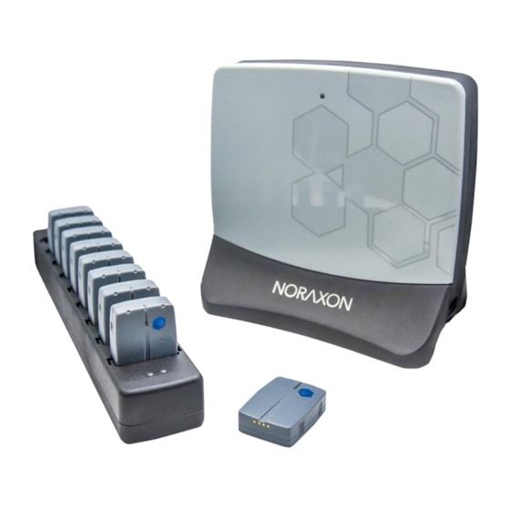
5 Setting up the Hardware 5.1 System Unboxing The Ultium Motion System is packed within a reinforced padded box for storage and protection during transport. Upon arrival, carefully remove all contents and verify the following components are present. Figure 1 – Ultium Sensor Charger (#873) Figure 2 –... -
Page 13: Ultium Receiver Overview
Ultium Motion Hardware User Manual Accessories If additional accessories have been included, please visit www.noraxon.com for more information. 5.2 Ultium Receiver Overview Receiver (Front) 1. Status LED – Indicates the status of the Receiver. 2. Charging Dock Port – Connects the Ultium Sensor Charger to the Receiver for communication. -
Page 14: Ultium Motion Sensor Overview
3. Charger Contacts – Sensor battery is charged and sensor data is exchanged through these points. Ultium Motion Sensor (Back) 1. Serial Number – Unique 5 character serial number which identifies each sensor. 2. Axis Indicator – Indicates the orientation of the Ultium Motion Sensor. (Rev B) -
Page 15: Hardware Setup Instructions
Ultium Motion Hardware User Manual 5.4 Hardware Setup Instructions Step 1 Insert the USB-B (smaller) end of the USB cable (CBL2) into the USB connector on the rear of the Ultium Receiver (880). Insert the opposite end of the USB cable into an available USB port on the computer. -
Page 16: Installing The Companion Software - Myoresearch™ 3
Ultium Motion Hardware User Manual 5.5 Installing the Companion Software – myoRESEARCH™ 3 To utilize the full functionality of the Ultium Motion System, and ensure the system has updated drivers, Noraxon’s myoRESEARCH 3 needs to be installed on the computer. -
Page 17: Configuring The Hardware
Ultium Motion Hardware User Manual 5.6 Configuring the Hardware Before the Ultium Motion System can be used, the device software settings must be configured to recognize the different components that make up the system. Follow the below instructions to update the receiver firmware, sensor firmware, and populate sensors to prepare for a data collection. - Page 18 Ultium Motion Hardware User Manual Step 4 Click the Sensors Tab. Place all Ultium Sensors into the chargers and attach the chargers to the Ultium Receiver. Select Detect Sensors in Charger to load all serial numbers into the MR3 software.
-
Page 19: Basic Operation Instructions
STATUS indicator will flash blue. When the sensor is actively measuring, the STATUS indicator will flash green. If the STATUS indicator is not flashing at all, the Ultium Motion Sensor may be powered off or may have a depleted sensor battery. -
Page 20: Attaching The Sensors
X-coordinate in line with a proximal orientation (i.e. towards the proximal joint along the long axis of the bone segment). Note: The X-coordinate points distally (toward the toes) for the feet sensors. Sensor Placement Assumptions for the Ultium Motion System: • Place sensors symmetrically between each sides of the body. - Page 21 Ultium Motion Hardware User Manual Sensor Placement Locations Head Middle of the back of the head Below C7 in line with the spinal column, but high Upper enough to not be affected by upper trapezius muscle Thoracic movement In line with the spinal column at L1/T12. Strap belt...
-
Page 22: Creating A New Configuration
Ultium Motion Hardware User Manual 6.5 Creating a New Configuration Step 1 Within the Home screen click the myoMOTION module icon. Create a New Subject. Note: Defining the height for the subject is important since the software uses subject height in its algorithm to compute bone... -
Page 23: Initialize A Measurement
Ultium Motion Hardware User Manual Configuration Options • Sensors: Select the sensors you wish to use in the recording by checking the boxes. • Joint Angles: Select the anatomical joint angles you want to capture in the recording. • Advanced: Enable wobbling correction setting and select reference frame for acceleration data. -
Page 24: Calibrating The Sensors
The calibration procedure defines the 0° point or 90° point (dependent on calibration position) of the angular displacement that is measured by each Ultium Motion Sensor. Particular attention should be used to ensure the calibration position is as accurate as possible. For example, if in standing straight position and the knee joint is not brought to the neutral zero joint position;... -
Page 25: Checking Signal Quality
Ultium Motion Hardware User Manual 6.8 Checking Signal Quality Check the signal quality by having the subject move around (e.g. walk, squat, raise arms, etc.), then confirm the joint angles, avatar display, and accelerations are appropriate for the subject’s motion. - Page 26 Ultium Motion Hardware User Manual Off – no correction applied to the myoMOTION model Foot, shank – Magnetic correction applied to the foot to shank joint angle to correct for heavy magnetic interference Foot, shank, thigh – Magnetic correction applied to...
-
Page 27: Record Signal As Desired
6.11 Shutdown After Use At the end of the day: • Place all Ultium Motion sensors inside the sensor docking station(s). • Apply AC wall power to the docking station (via PSU1 connected to the Ultium Receiver). •... -
Page 28: Unexpected Errors
Ultium Motion Hardware User Manual 6.13 Unexpected Errors Error Message Meaning The following sensors are not available: Ultium Motion One or more sensors failed to Please make sure they are not being charged and are respond to a start measurement command. The within range. -
Page 29: Additional Ultium Motion Settings & Features
General tab. To enable Sync, simply check the Use Noraxon MyoSync checkbox. When Use Noraxon MyoSync is enabled in Hardware Setup, the digital channel will be labeled Sync. If MyoSync is not enabled, the channel will be labeled Switch and can be used as a generic digital input. -
Page 30: Myomotion Software Settings
Ultium Motion Hardware User Manual 7.2 myoMOTION Software Settings myoMOTION Software settings are in a myoMOTION tab in the Software Setup in the Home screen. There are 3 different options: Magnetometer Control, Magnetometer Table, and Secondary Knee Angles. 7.2.1 Magnetometer Control... -
Page 31: Using Object Sensors
Ultium Motion Hardware User Manual 7.2.2 Magnetometer Table Selecting this feature in Software setup allows the user to turn off the magnetometer table seen in the Measure screen. The table can be disabled if the magnetometer table is not useful for the user’s application or they know that they have magnetically clean data. - Page 32 Ultium Motion Hardware User Manual Step 3 Select Edit configuration. Once inserted into the hardware configuration, the object sensors will appear available in the software configuration under the sensors tab: object sensors. Step 4 On (checkbox) – enables the sensor to be...
-
Page 33: Enabling Contact Detection
Ultium Motion Hardware User Manual 7.4 Enabling Contact Detection The contact detection feature uses the gyroscope and accelerometer data from the sensors assigned to the feet to determine when the foot is in stance and swing phase via an on/off signal. -
Page 34: Anti-Wobble Mode
Ultium Motion Hardware User Manual interval. Any additional information from the record, such as EMG signals, will be displayed in the same manner as the kinematic angles. 7.5 Anti-Wobble Mode Anti-wobble mode can be used to smooth data susceptible to soft tissue artifact. Soft tissue artifact occurs when the sensor moves relative to the skin, which creates a “wobble”... -
Page 35: Lossless Data Recovery
Ultium Motion Hardware User Manual 7.6 Lossless Data Recovery The Ultium System supports “lossless” data recovery. The sensors continue to capture and store data (>8 hours of data) when communication is temporarily lost with the receiver. Once the record is completed, the data can be recovered in real-time or at a later time using the Import function. -
Page 36: Maintenance
Maintenance Routine maintenance recommended for the Ultium Motion system involves cleaning the bottom pads of the Ultium Motion Sensor periodically and zeroing the gyros daily. Because the Ultium Motion sensor batteries are Li-Polymer, the only battery maintenance required is recharging. -
Page 37: Zero Gyros
Ultium Motion Hardware User Manual 8.3 Zero Gyros Zeroing the gyroscope in the Ultium Motion Sensor is generally recommended to keep the sensor data accurate. It is recommended to zero gyros daily. To do this, follow these steps: 1. Place sensors above the ground away from any magnetic interference. -
Page 38: Cleaning The Ultium Motion Sensors
Safety precautions for cleaning the Ultium Motion Sensors: For sanitary purposes, it is advisable to clean the back of the Ultium Motion Sensors on a regular basis. The Ultium Motion Sensors can be cleaned with a cloth slightly dampened with a solution of mild soap and water or disinfectant solution (i.e. -
Page 39: Companion Software Updates
The internal program (firmware) inside the various Ultium devices can be updated via MR3. If the operating PC is connected to the internet, the user will be notified when an update is required. All Ultium Motion Sensors should be fully charged before a firmware update is performed. -
Page 40: Battery Replacement
8.8 Battery Replacement 8.8.1 Battery Life Expectations The Lithium Polymer battery used in the Ultium Motion Sensors is rated for a minimum of 300 charge- discharge cycles. Typical usage is 500 charge-discharge cycles. As the number of charge-discharge cycles increases the battery capacity slowly declines thereby reducing run time despite being fully charged. -
Page 41: Troubleshooting & Fault Diagnosis
USB Driver is not installed Check the Device Manager for USB driver errors and update the driver if needed Symptom: Problems with Ultium Motion Sensors communicating with the Ultium Receiver Possible Reason Remedial Action Sensors were not assigned to Receiver... -
Page 42: Radio Considerations
Reliable transmission depends on good signal quality. Signal quality will fall with extended distances between the Ultium Receiver and the Ultium Motion Sensors. Obstructions (walls, metal structures, trees, etc.) between the Ultium Receiver and the Ultium Motion Sensors will also lower the signal quality. -
Page 43: Support, Service, & Repair
If you are shipping from outside the USA please use UPS, FedEx, DHL, or EMS (US Postal Service) and not a freight-forwarder. Using a freight-forwarder incurs additional brokerage fees. If a package is shipped to Noraxon via a carrier other than the ones listed above, it may be refused. 11 Taking Product Out of Operation 11.1 Disposal of Equipment &... -
Page 44: Technical Information
The #870 & #876 Ultium Motion Sensors are powered by one 150mAh battery; each is identified by a unique serial number. The opposite end of the #870 & #876 Ultium Motion Sensors have 4 contact pads for recharging its battery and communication. To recharge the battery, the #870 & #876 Ultium Motion Sensors are placed inside a docking station. -
Page 45: Electro-Magnetic Compatibility Tables
Ultium Motion Hardware User Manual 12.2 Electro-Magnetic Compatibility Tables Guidance and manufacturer’s declaration – electromagnetic emissions The Ultium System is intended for use in electromagnetic environment specified below. The customer or the user of the Ultium System should assure that it is used in such an environment. - Page 46 RF transmitters, an electromagnetic site survey should be considered. If the measured field strength in the location in which the Ultium Motion Sensor & Receiver s used exceeds the applicable RF compliance level above, the Ultium Motion Sensor & Receiver should be observed to verify normal operation.
- Page 47 Ultium Motion Hardware User Manual Over the frequency range 150 kHz to 80 MHz, field strengths should be less than 3 V/m (Rev B)
- Page 48 Ultium Motion Hardware User Manual Recommended separation distances between portable and mobile RF communications equipment and the Ultium System The Ultium System is intended for use in an electromagnetic environment in which radiated RF disturbances are controlled. The customer or the user of the Ultium System can help prevent electromagnetic interference by maintaining a minimum distance between portable and mobile RF communications equipment (transmitters) and the Ultium System as recommended below, according to the maximum output power of the communications equipment.
-
Page 49: Appendices
13.1 Appendix A – Product Specifications Expected Useful Lifetime Both the Ultium Receiver (880) and Ultium Motion Sensors (870/876) have a usable life of seven years. The Ultium Motion Sensors (#810 & #876) operate with a rechargeable Lithium Polymer battery. The battery capacity will decline with ongoing use and require replacement after 300+ discharge/charge cycles to preserve the device’s rated 8 hours of operating time. - Page 50 GFSK 2402-2480 MHz, frequency hopping • Utilizing up to 79 hopping channels • Channel-to-channel hopping frequency: 50Hz (20 ms) • Ultium Motion sensor transmission range: 40m (typical) Ultium Motion Sensor Data Acquisition System • 16-bit data resolution • Measurement ranges:...
- Page 51 Ultium Motion Hardware User Manual Energy Consumption, Condition of Use • Ultium Receiver is powered by 5VDC USB host • Ultium Sensor Charger is powered by 5VDC at 3.0A using a 110-240 VAC 50/60 Hz external supply (PSU1) Environmental Conditions for Normal Operation •...
-
Page 52: Appendix B - Radiation Exposure Information Regarding Use Of Ultium Motion Sensors
Each Ultium Motion Sensor contains a radio frequency transmitter. The radiated power emitted from each individual Ultium Motion Sensor is very low. To put this in perspective, at full power each Ultium Motion Sensor transmits at less than 0.8% of the power of a typical active cell phone. Radiation exposure from a single Ultium Motion Sensor is thus extremely low. -
Page 53: Appendix C - Radio Regulatory Statements
Ultium Motion Hardware User Manual 13.3 Appendix C – Radio Regulatory Statements FCC Statement This device complies with part 15 of the FCC rules. Operation is subject to the following two conditions: (1) This device may not cause harmful interference, and (2) this device must accept any interference received, including interference that may cause undesired operation. -
Page 54: Appendix D - Ultium Led Status Guide
13.4 Appendix D – Ultium LED Status Guide Both the Ultium Motion Sensor and Receiver have an LED located on the front face which displays the status of the sensor or receiver. Please reference the following list for information on what each LED status means.
Need help?
Do you have a question about the Ultium Motion and is the answer not in the manual?
Questions and answers