
Summary of Contents for C-COR Flex Max901e
- Page 1 Meeting the demands of an on demand world.™ Flex Max901e 1GHz Amplifiers Equipment Manual 1502154 Revision D...
- Page 3 Flex Max901e 1GHz Amplifiers Trunks (FMTE) and Bridgers (FMBE) 1502154 Revision D...
- Page 4 Copyright © 2006 C-COR Incorporated. All rights reserved. Trademarks C-COR is a registered trademark and CHP Max, Flex Max, and PLEXiS are trademarks of C-COR Incorporated. All other brand and product names are trademarks or registered trademarks of their respective companies.
- Page 5 Phone: +31 36 546 1170 Repair Services Contact Repair Services to request a Return Material Authorization (RMA) if you need to return a product for repair. Please go to the C-COR website for Repair Services contact information. 1502154 Rev D...
- Page 6 Phone: +31 36 546 1171 Technical Publications C-COR Technical Publications welcomes your suggestions and assistance in identifying any errors, inaccuracies, or misleading information. Prior to notifying Technical Publications, please check the website to ensure that you have the most up-to-date revision of the manual. When responding, please reference the document number and page number(s) to which your feedback applies.
-
Page 7: Table Of Contents
Flex Max901e Trunk and Bridger Amplifier........ -
Page 8: Voltage Testing
Flex Max901e Trunk Amplifier Configured for 870MHz operation with 14.5dB Output Tilt 5-12 Flex Max901e Bridger Amplifier Configured for 1GHz Operation ....5-13 Flex Max901e Bridger Amplifier Configured for 870MHz Operation .... -
Page 9: Specifications
B-14 Flex Max901e Bridger Amplifier, 1002MHz, 55/70 Split ......B-17 Flex Max901e Trunk Amplifier, 1002MHz, 65/85 Split, 33dB Spaced, Different Tilt on Trunk and Bridger. - Page 10 Flex Max901e 1GHz Trunk and Bridger Amplifiers 1502154 Rev D...
-
Page 11: Introduction
C H A P T E R Introduction This chapter includes an overview of Flex Max901e 1 GHz Trunk and Bridger Amplifiers, document conventions, compliance statements, and suggested tools and materials required when working with these amplifiers. How This Manual is Organized — page 1-1 Overview —... -
Page 12: Overview
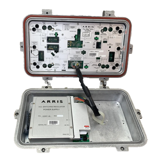
Overview Flex Max901e 1 GHz Trunk and Bridger Amplifiers are the new industry standard for RF distribution products. The FM901e continues to offer the same excellent features, reliability, and performance customers have come to rely on with C-COR’s legacy 700/800/900/901 series amplifiers. In... - Page 13 Figure 1.1 Flex Max901e Standard Flex Max 6-Port Housing FMTE RF Module High Efficiency Power Supply (HEPS) 1502154 Rev D Introduction...
-
Page 14: Part Numbers (Model Options)
Select "7" if future element management transponder is planned. AM protocol (P/N 810-0354-01A) HMS protocol (P/N 810-0354-01H) c) Operation of return switches requires a transponder. b) Must order mounting bracket kit (P/N 1501024) Flex Max901e 1GHz Trunk and Bridger Amplifiers 1502154 Rev D... -
Page 15: Flex Max901E Bridger Amplifiers
Flex Max901e Bridger Amplifiers – Series Output Configuration a, e Flex Max901e series Two bridger outputs—user-configurable to 4 outputs with –25dB External testpoints a) 15A current passing capability. b, e Two bridger outputs—user-configurable to 4 outputs with –20dB Internal testpoints... -
Page 16: Part Number Example
Value Max transponders. Document Conventions This manual uses a different typeface to show text that is printed or silkscreened on Flex Max901e modules. For example, ALC is silkscreened on the RF module faceplate to indicate the Automatic Level Control switch setting. -
Page 17: Statements Of Compliance
Changes or modifications to this device not expressly approved by C-COR Corp. may cause the operation of this device to be in violation of Part 76 of the FCC Rules, voiding the user’s authority to operate the equipment. -
Page 18: Tools And Materials
Table 1.1 describes the tools, equipment, and materials that may be required to operate, maintain, and test the Flex Max901e. Anyone performing the procedures in this manual is expected to be familiar with the appropriate and safe use of these tools. Tools or equipment with equivalent or superior specifications may be substituted for those listed. - Page 19 Table 1.1 Tools and Materials (cont’d) Tools/Equipment Required Characteristics Uses Materials 1/4-20 UNC bolts and flat — Wall mounting washers Heat gun or approved — Weatherproofing RF cable and fiber optic torch and heatshrink stub cable connectors tubing, or weathersealing tape or compound Anti-seize compound —...
- Page 20 1-10 Flex Max901e 1GHz Trunk and Bridger Amplifiers 1502154 Rev D...
-
Page 21: Physical Identification
Physical Identification This chapter identifies and describes user-accessible testpoints, controls, plug-in locations, connections, modules, and components for the Flex Max901e amplifiers. For specific testpoints, controls, and connections for the power supply and AC distribution board, refer to Power Supply Configuration on page 5-3. For information on the element management transponder, refer to Housing Replacement on page 7-13. -
Page 22: Flex Max901E Trunk And Bridger Amplifier
PORT 2/3 REV PORT 5/6 REV AMPS AMPS I/P TP I/P TP High Efficiency Switching Fuse Cover Power Supply H.E. SWITCHING REGULATOR POWER SUPPLY SERIAL NO. AC IN RAW DC Flex Max901e 1GHz Trunk and Bridger Amplifiers 1502154 Rev D... - Page 23 Table 2.1 Testpoints, Plug-in Locations, Controls, and Connections Item Label Function PORT 1 Provides access to the Port 1 centerseizure screw. PORT 1 Provides access to the Port 1 centerseizure screw (90° rotation). Directional testpoint for measuring incoming forward RF signals. PORT 1 FWD I/P TP PORT 1 REV O/P TP Directional testpoint for measuring outbound return RF signals.
- Page 24 Screws Refer to functional block diagrams (Appendix C) and reference tables (Appendix D) for more information. Refer to Factory-Shipped Configurations for Flex Max901e Trunk and Bridger Amplifiers on page 5-9 for more information. Flex Max901e 1GHz Trunk and Bridger Amplifiers...
-
Page 25: Transponder Identification
Figure 2.2 Transponder Identification LOCAL Value Max STATUS Transponder xx-xx-xx-xx-xx-xx MAC ADRS: xxxxxx AM ADRS: Actual size Table 2.2 Transponder Identification Item Label Function Grounding Bracket Connects transponder to ground Interface Connector Provides connection to RF board and element management system Tamper Switch Detects open lid LOCAL... -
Page 26: Plug-In Accessory Insertion Guides
Installed to be Installed STATION FWD EQ DISTRIBUTION Slot A SS-1000-2 SEQ-750-xx SS-1000-8 SEQ-870-xx SS1000-12 Slot SCS-750-xx SCS-870-xx Slot B SEQ-1GHz-xx SCS-1GHz-xx STATION REV EQ Slot B Slot MEQ/MEQT-xx-xx Flex Max901e 1GHz Trunk and Bridger Amplifiers 1502154 Rev D... -
Page 27: Upgrading Legacy Flexnet Amplifiers
Upgrading Legacy FlexNet Amplifiers Note C-COR 700, 800, and 900 series amplifiers can be upgraded to the Flex Max901e. The Flex Max901e module can be placed in existing 700, 800, and 900 series locations without the need for respacing. ®... -
Page 28: Upgrade Considerations
Although upgrading an existing 700/800/900 series FlexNet trunk or bridger amplifier to a Flex Max901e enables reuse of the housing and maintenance of amplifier spacing, there are five major issues to consider: Hazardous voltages are present. -
Page 29: Tools Required
Table 3.1 describes the tools that may be required to upgrade an existing FlexNet trunk and bridger amplifier to a Flex Max901e. Anyone performing the procedures in this chapter is expected to be familiar with the appropriate and safe use of these tools. Tools or equipment with equivalent or superior specifications may be substituted for those listed. -
Page 30: Housing Opening
While holding the cover closed with one hand, release the last two captive cover bolts, and open (lower) the cover. Figure 3.1 Housing Lid Bolt Loosening Sequence Flex Max901e 1GHz Trunk and Bridger Amplifiers 1502154 Rev D... -
Page 31: Rf Module Upgrade
Ensure that you have completed the necessary power supply upgrade requirements before proceeding. Note The Flex Max901e RF module requires a minimum 2.3 A power supply and uses a 12-pin connector. FlexNet 700 series amplifiers used 9-pin connectors. To prepare for the Flex Max901e RF module upgrade, it may be necessary to use a cable adapter (9-pin to 12-pin) or upgrade to a new power supply (P/N 122027-05). - Page 32 P/N 173720-02 10 inch cable 9-pin to 12-pin cable adapter 12-pin cap 12-pin cap 122027-05 FM901e power supply module P/N 174355-02 14 inch cable 12-pin to 12-pin detachable cable Flex Max901e 1GHz Trunk and Bridger Amplifiers 1502154 Rev D...
-
Page 33: Replacement
Figure 3.3 Power Supply Upgrade Requirements HEPS790-2.3 Power Supply HEPS790-1.8 Power Supply #122027-01 #122027-01 HEPS700-1.8 Power Supply #122019-11 #122019-10 122027-03 These two power supplies have a 9-pin cable and require a 9-pin to 12-pin cable adapter OR replace with a 122027-05 power supply and 174355-02 detachable cable. - Page 34 Grasp the RF module handles and pull the RF module straight out of the housing. To install the Flex Max901e RF module Orient the Flex Max901e RF module appropriately. Align the RF module back pins with the receptacles located on the centerseizure assemblies.
-
Page 35: Cable Adapter (9-Pin To 12-Pin) Installation
C-COR FlexNet 700 Series trunk and bridger amplifiers use 9-pin cables to connect the power supply to the RF module; however, the Flex Max901e module requires a 12-pin connector. To upgrade to the Flex Max901e RF module, a cable adapter is required. -
Page 36: Housing Closing And Tightening
If the housing is equipped with external testpoints, install testpoint caps on all testpoints and finger tighten. Use a wrench to tighten the caps an additional one quarter to one half turn. Figure 3.7 Housing Closing and Tightening Sequence 3-10 Flex Max901e 1GHz Trunk and Bridger Amplifiers 1502154 Rev D... -
Page 37: Housing Instructions
C H A P T E R Housing Instructions This chapter describes recommended cable attachment procedures and proper opening and closing procedures to be used when accessing the internal components. Tools and Materials — page 4-1 Preparing for Installation — page 4-2 Housing Opening —... -
Page 38: Preparing For Installation
Small, hold-down screws may be Phillips head screws or Torx PLUS head screws. Use the appropriate driver. ® C-COR recommends torquing all bolts and screws to the specified values. Preparing for Installation CAUTION Check the unit for damage. If there is shipping damage, contact the shipping company and the C-COR Customer Service Department. - Page 39 Figure 4.1 Housing Inspection Lid Bolts (Outside) Standard Front View 6-Port Housing (Internal Testpoints) Wall Mount Bosses Back View Cable Convection Entry Ports Fins Bypass 6-Port Housing Front View (External Testpoints) Top Strand Mount Bosses Back View Optional External Testpoints 1502154 Rev D Housing Instructions...
- Page 40 Mounting With Extension Mounting Brackets (EMBs) on page 4-8 or Wall Mounting With Extension Mounting Brackets (EMBs) on page 4-12. EMBs are not included with the unit but may be purchased separately. Contact your C-COR sales professional for ordering information.
-
Page 41: Housing Opening
Housing Opening The electronic components of the Flex Max901e are enclosed in a specialized, diecast aluminum housing. Proper installation and other housing-related operations are important to ensure the integrity of the electronics within. WARNING Hazardous voltages are present. Use approved safety equipment and procedures. -
Page 42: Housing Mounting
Position the housing at a location on the strand that is accessible for attaching cables and performing maintenance and balancing, and that complies with the requirements of the system. Torque the clamp bolts to between 40 and 66 in-lbs (4.5 and 7.5 N·m). Flex Max901e 1GHz Trunk and Bridger Amplifiers 1502154 Rev D... - Page 43 Figure 4.4 Strand/Pedestal 1-inch Clamp 1-inch Clamp Bolt Mounting Bolt Lock Lock Washer Washer Strand Strand Clamp Clamp O-Ring O-Ring (retaining) (retaining) Strand Strand Clamp Clamp 1/4-inch 5/16-inch Boss Strand Boss Strand Strand Clamp Orientation Strand Clamp Orientation for 1/4-inch Strand or Smaller for 5/16-inch Strand or Larger 1502154 Rev D Housing Instructions...
-
Page 44: Strand/Pedestal Mounting With Extension Mounting Brackets (Embs)
Strand/Pedestal Mounting With Extension Mounting Brackets (EMBs) Use EMBs to mount a Flex Max901e if additional space is required between the unit and the strand. The following kits are available: 3.2-inch (8 cm) EMB (P/N 172187-01) 6-inch (15 cm) EMB (P/N 172187-03) Note EMBs are not included with the unit but may be purchased separately. - Page 45 Figure 4.5 Strand/Pedestal 1-inch 1-inch Clamp Bolt Clamp Bolt Mounting with EMBs Strand Clamp Strand Clamp 1/4-inch O-Ring 5/16-inch O-Ring Strand (retaining) Strand (retaining) Lock Lock Washer Washer 1/2-inch 1/2-inch EMB Bolt EMB Bolt Lock Lock Top Strand Washer Washer Strand Clamp Clamp...
-
Page 46: Wall Mounting Using Wall Mounting Bosses
Wall Mounting Using Wall Mounting Bosses Use the wall mounting bosses (mounting surfaces) when mounting a Flex Max901e to a wall. Refer to Figure 4.6 To wall mount with wall mount bosses Measure the thickness of the surface where the housing will be located. - Page 47 Figure 4.6 Wall Mounting with Wall Mount Bosses Wall Mount Boss Wall Mounting Bolt Lock Washer Flat Washer 11.8 in. (30.0cm) 1502154 Rev D Housing Instructions 4-11...
-
Page 48: Wall Mounting With Extension Mounting Brackets (Embs)
Wall Mounting With Extension Mounting Brackets (EMBs) Use EMBs to mount a Flex Max901e if additional space is required between the unit and the mounting surface. The following kits are available: 3.2-inch (8 cm) EMB (P/N 172187-01) 6-inch (15 cm) EMB (P/N 172187-03) Note EMBs are not included with the unit but may be purchased separately. -
Page 49: Wall Mounting With Embs
Figure 4.7 Wall Mounting with Extension Mounting Bracket Mounting EMBs 3.2-inch (8cm) EMB (P/N 172187-01) Bolt 6-inch (15cm) EMB (P/N 172187-03) Flat 1/2-inch Washer EMB Bolt Lock Lock Washer Washer Top Strand Clamp Boss Wall 8.5 in. (21.6cm) 1502154 Rev D Housing Instructions 4-13... -
Page 50: Cable Attachment
The boot must also extend at least 2 inches (5.08 cm) beyond the back nut. Slide the boot further onto the cable to allow access to the end of the cable. Refer to Figure 4.9. Figure 4.9 Heatshrink Boot 4-14 Flex Max901e 1GHz Trunk and Bridger Amplifiers 1502154 Rev D... - Page 51 Using connectors with center conductors exceeding 0.080 inches (2.03 mm) in diameter will damage the centerseizure mechanism. Note Because Flex Max901e 6-port housings have extended port inserts to better accommodate heatshrink boots, stinger lengths should be measured from the mating surface of the O-ring on the cable connector to the tip of the center conductor.
- Page 52 Table 4.3 STANDARD Flex Max901e Housing Center Conductor Lengths (images not to scale) IF you have a housing in which the port insert extends... THEN cut the center conductor to... 9/16in (1.43cm) 11/2in (3.81cm) 3/16in (0.48cm) 1 1/8in (2.86cm) Table 4.4 BYPASS Housing Center Conductor Lengths (images not to scale) IF you have a housing where the port insert extends...
- Page 53 Figure 4.10 Cable Connector Back Nut Main Nut Connector Body Assembly more than 0.080 in (2.03 mm) diameter Radiation O-rings Sleeve External threads located on back Variations: Back Nut Main Nut/ Connector Body 90° Elbow Connector Apply anti-seize compound to threads and O-ring. Do not use spray lubricant. CAUTION Do not let the center conductor contact the RF module chassis.
- Page 54 Heat the boot to shrink it securely around the insert, connector, and cable as specified by the shrink tubing manufacturer. 4-18 Flex Max901e 1GHz Trunk and Bridger Amplifiers 1502154 Rev D...
-
Page 55: Housing Closing And Tightening
Housing Closing and Tightening CAUTION Ensure that no wire scraps or foreign materials remain within the housing CAUTION Close the housing whenever it is left unattended to keep moisture out of the unit and protect the network from RF interference. To close the housing Examine the rubber gasket and mesh seal. - Page 56 4-20 Flex Max901e 1GHz Trunk and Bridger Amplifiers 1502154 Rev D...
-
Page 57: Configuration
C H A P T E R Configuration This chapter provides instructions for the initial setup of Flex Max901e 1 GHz Trunk and Bridger Amplifiers. Power Supply Configuration — page 5-3 Calculating Balancing Carrier Levels — page 5-6 Temperature Compensation — page 5-6 Factory-Shipped Configurations for Flex Max901e Trunk and Bridger Amplifiers —... - Page 58 “across the flat” dimensions. Small, hold-down screws may be Phillips head screws or Torx PLUS head screws. Use the appropriate driver. ® C-COR recommends torquing all bolts and screws to the specified values. Flex Max901e 1GHz Trunk and Bridger Amplifiers 1502154 Rev D...
-
Page 59: Power Supply Configuration
WARNING Hazardous voltages are present. Use approved safety equipment and procedures. CAUTION To prevent hybrid damage, C-COR recommends that all amplifiers in a power supply group have PADs and Equalizers installed in the forward RF path before energizing. The initial recommended accessory values are shown on the system map. - Page 60 Figure 5.1 HEPS790-2.3A (122027-05) PORT 1 PORT 4 AC Distribution MAIN FUSE Link DIST LINK 122027-05 PORT 2 PORT 3 PORT 5 PORT 6 Figure 5.2 Power Routing Diagram Flex Max901e 1GHz Trunk and Bridger Amplifiers 1502154 Rev D...
-
Page 61: Voltage Testing
Voltage Testing CAUTION Testing voltage at any centerseizure screw in an operating system may interfere with, or cause the loss of, signal to the subscriber. Note AC measurements may read up to 10% error if a true RMS meter is not used. AC ripple measurements cannot be made without an AC-coupled meter. -
Page 62: Calculating Balancing Carrier Levels
When the temperature surrounding an amplifier is between 50 and 90• F (10 and 32• C), balancing carrier levels do not require temperature compensation. If the temperature is less than 50• F (10• C) or greater than 90• F (32• C), perform temperature compensation as follows: Flex Max901e 1GHz Trunk and Bridger Amplifiers 1502154 Rev D... - Page 63 Find the TCV line nearest this point. The dB value label on that line is your TCV. Record both TCVs in the calculation box below and on the Flex Max901e Data Sheet. Example: Your cable loss is 23 dB. The air temperature is 25° F (–5° C). The point on the graph corresponding to these two values is between the 0.75 and 1.0 dB lines,...
- Page 64 Figure 5.3 Temperature Temperature (°C) Compensation Value Chart Temperature (°F) Flex Max901e 1GHz Trunk and Bridger Amplifiers 1502154 Rev D...
-
Page 65: Factory-Shipped Configurations For Flex Max901E Trunk And Bridger Amplifiers
Flex Max901e Trunk Amplifier Configured for 1 GHz Operation with Equal Output Tilt on the Trunk and Bridger Legs — page 5-11 Flex Max901e Trunk Amplifier Configured for 870 MHz operation with 14.5 dB Output Tilt — page 5-12 Flex Max901e Bridger Amplifier Configured for 1 GHz Operation — page 5-13 Flex Max901e Bridger Amplifier Configured for 870 MHz Operation —... -
Page 66: Transponder
Flex Max901e Trunk Amplifier with Optimized Tilt for 1GHz Operation with Trunk and Bridger Legs at Different Output Tilts Note The following example is how this Flex Max901e is shipped from the factory. Ensure that a GEQL-1GHZ-090 (9 dB) is installed in the BRIDGER EQ/PAD location. - Page 67 Flex Max901e Trunk Amplifier Configured for 1GHz Operation with Equal Output Tilt on the Trunk and Bridger Legs Note The following example is how this Flex Max901e is shipped from the factory. Note This FM901e configuration is suitable for replacement of FNT7, FNT8, FNT9 amplifiers.
- Page 68 Flex Max901e Trunk Amplifier Configured for 870MHz operation with 14.5dB Output Tilt Note The following example is how this Flex Max901e is shipped from the factory. Note After initial setup, 870 MHz equalizers and cable simulators may be used. Ensure that a GEQC-870-080 (8 dB) or a GEQC-1 GHz-090 (9 dB) is installed in the O/P EQ location.
-
Page 69: Flex Max901E Bridger Amplifier Configured For 1Ghz Operation
Flex Max901e Bridger Amplifier Configured for 1GHz Operation Note The following example is how this Flex Max901e is shipped from the factory. Install NPB-000 PADs in the following locations: – INTERSTAGE PAD – BRIDGER EQ/PAD – P5/P6 FWD PAD Do not remove the jumper installed in the INTERSTAGE EQ location. -
Page 70: Flex Max901E Bridger Amplifier Configured For 870Mhz Operation
Flex Max901e Bridger Amplifier Configured for 870MHz Operation Note The following example is how this Flex Max901e is shipped from the factory. Install NPB-000 PADs in the following locations: – INTERSTAGE PAD – P5/P6 FWD PAD Install an NPB-020 PAD in the following location: –... -
Page 71: Forward Balancing
ALC operating range for NTSC or QAM channel pilot operation prior to performing the forward balancing procedure The ALC setup range in Flex Max901e amplifiers originally featured a pilot frequency setup range of +2/-6 dB at standard output levels. To achieve this range, amplifiers shipped with a factory-installed ALC PAD (see table below). -
Page 72: Forward Balancing Requirements
Preceding amplifiers have been properly balanced and provide the desired forward band signals to the amplifier for forward balancing. Flex Max901e trunk and bridgers amplifiers can be configured with the appropriate plug-in accessories for 1GHz operation or for use as spares in 750/870MHz systems. Refer to Power Supply Configuration beginning on page 5-3. -
Page 73: Forward Balancing Procedure
Forward Balancing Procedure Refer to Figure 2.1 and Table 2.1 for control and accessory locations. To balance the forward path Determine the System Forward High and Low Balancing Carrier Levels: If bandedge carriers are used for balancing, copy the amplifier bandedge carrier output levels from the system map to the Map Signal Information table on the Amplifier Data Sheet. - Page 74 Measured High and Low Balancing Carrier Levels. Record these levels as shown in the box that follows. Calculate System Tilt, Measured Tilt, and Equalization Value. 5-18 Flex Max901e 1GHz Trunk and Bridger Amplifiers 1502154 Rev D...
- Page 75 – System Forward High System Forward Low System Tilt Balancing Carrier Level Balancing Carrier Level – Measured Forward High Measured Forward Low Measured Tilt Balancing Carrier Level Balancing Carrier Level – System Tilt Measured Tilt Equalization Value If the Equalization Value is positive, an SEQ is needed. If the value is negative, an SCS is needed.
-
Page 76: Return Balancing
When using the single-person method, turn off the ALC, if present, in the return rack mount receiver at the headend. The following sections cover the single and two person balancing procedures. 5-20 Flex Max901e 1GHz Trunk and Bridger Amplifiers 1502154 Rev D... -
Page 77: Single Person Return Balancing Procedure
Note If a unit closer to the headend is balanced incorrectly, all succeeding amplifiers will not be balanced correctly using the single person method. Figure 5.10 Typical Headend Flex Max901e Configuration of Single Person Return Balancing Equipment A device (usually rack... -
Page 78: Two Person Return Balancing
Note The return path is not active until the PADs and return EQ accessories are installed. Note Testpoints are –20 dB referenced to the associated port input or output level. Refer to the housing label for testpoint loss. 5-22 Flex Max901e 1GHz Trunk and Bridger Amplifiers 1502154 Rev D... - Page 79 Steps 3c and 4a. (Return input levels may vary depending upon the input port.) Set the Flex Max901e as follows: At the Balancing Amplifier, ensure that NPB-000/SEQ-0 accessories are installed in the STATION REV PAD and STATION REV EQ locations.
- Page 80 Record these levels on the Amplifier Data Sheet. Close the housing and replace the caps on all external testpoints. (Refer to Housing Closing and Tightening on page 4-19, if necessary.) 5-24 Flex Max901e 1GHz Trunk and Bridger Amplifiers 1502154 Rev D...
-
Page 81: Troubleshooting
Return Field Testing — page 6-5 Overview These procedures check all operational characteristics of a Flex Max901e that is suspected of being faulty. Troubleshooting flow diagrams are provided beginning on page 6-7. The following information is required for Forward and Return Field Testing:... -
Page 82: Tools And Materials
“across the flat” dimensions. Small, hold-down screws may be Phillips head screws or Torx PLUS head screws. Use the appropriate driver. ® C-COR recommends torquing all bolts and screws to the specified values. Flex Max901e 1GHz Trunk and Bridger Amplifiers 1502154 Rev D... -
Page 83: Quick Forward Outage Check
You can combine this method with other methods. An Flex Max901e that outputs reasonable RF signal levels may not pass power to the next device (likely due to a blown fuse). The lack of power passing is then caught when the next active device in the signal path is checked, which leads you back to the problem amplifier. -
Page 84: Forward Field Testing
Amplifier Data Sheet. If necessary, rebalance the amplifier. Note The Operational Gain listed on a C-COR Amplifier Specification Sheet is the gain at the high bandedge frequency and includes loss equal to the forward equalizer plug-in value. -
Page 85: Return Field Testing
Reset the ALC/MAN switch to ALC. Adjust the ALC SENSITIVITY control as described in Factory-Shipped Configurations for Flex Max901e Trunk and Bridger Amplifiers on page 5-9. Return Field Testing CAUTION RF signal levels greater than +90 dBmV (1 return NTSC channel) injected into a forward output testpoint can damage amplifier active components. - Page 86 Note The Operational Gain listed on a C-COR Amplifier Specification Sheet is the gain at the high bandedge frequency and includes 1.0 dB of loss for the return equalizer. Calculate the true return amplifier gain by subtracting the input signal level (set in Step 2) from the output level measured at the PORT 1 REV O/P TP.
- Page 87 Figure 6.3 Troubleshooting Flow Diagram (1 of 2) 1502154 Rev D Troubleshooting...
- Page 88 RF correct? module. If still not within range, replace the housing. Troubleshooting procedure has been successfully completed. All amplifier voltage and signal levels are correct. Flex Max901e 1GHz Trunk and Bridger Amplifiers 1502154 Rev D...
-
Page 89: Maintenance
® upgrading an existing 750 MHz and 870 MHz FlexNet trunk and bridger amplifiers to the Flex Max901e 1002 MHz amplifiers. Tools and Materials — page 7-2 General Inspection — page 7-3 Fuse Shorting Bar (Slug) Replacement — page 7-3 Return Switch Installation —... -
Page 90: Tools And Materials
“across the flat” dimensions. Small, hold-down screws may be Phillips head screws or Torx PLUS head screws. Use the appropriate driver. ® C-COR recommends torquing all bolts and screws to the specified values. Flex Max901e 1GHz Trunk and Bridger Amplifiers 1502154 Rev D... -
Page 91: General Inspection
CAUTION Ensure that your shorting bar is plated with the same material as the fuse clips. Differing materials may cause corrosion which may damage the fuse clips. C-COR slugs are plated with the same material as the fuse clips. To remove the fuse Remove the fuse/slug using a fuse puller. -
Page 92: Return Switch Installation
Return Switch Installation Note A Value Max Transponder needs to be installed in a Flex Max901e to operate the return switches. The procedure to install a Value Max Transponder is provided in Element Management Transponder Installation/Replacement on page 7-10. This section provides the bench procedure to install return switches in a Flex Max901e trunk amplifier (P/N FMTExxx-xxxxxxxN) or a Flex Max901e bridger amplifier (P/N FMBExxx-xxxxxxxN) that was purchased without return switches. -
Page 93: Location
Figure 7.1 Location of the Jumper W17 for Return Switch RS1 Jumper W18 for Return Switch RS2 Jumper and Return Switch in the Flex Max901e Trunk and Bridger Amplifiers Jumper W19 for Return Switch RS3 Figure 7.2 Return Switches Return Switch RS2... - Page 94 Torque to between 25 and 27 in-lbs (2.8 and 3.1 N·m). Connect the power supply plug to the RF module POWER PLUG connector. 10. Perform the Forward and Return Field Test described in the Flex Max901e 1 GHz Amplifiers Equipment Manual, 1500335.
-
Page 95: Rf Module Replacement
RF Module Replacement The RF module can be installed in the housing in one of two orientations (refer to Figure 7.3). When installing fuses, surge terminators, or brass shorting bars to route AC power, note that the power supply fuses are associated with the RF module ports and not the housing ports. WARNING Hazardous voltages are present. -
Page 96: Orientation Options
Connect the power supply plug to the RF module POWER PLUG connector. Perform the Forward and Return Field Tests. Refer to Forward Field Testing on page 6-4 and Return Field Testing on page 6-5. Flex Max901e 1GHz Trunk and Bridger Amplifiers 1502154 Rev D... -
Page 97: Power Supply Replacement
Power Supply Replacement WARNING Hazardous voltages are present. Use approved safety equipment and procedures. To remove the power supply Disconnect the power supply plug from the RF module POWER PLUG connector. Use a #2 Phillips screwdriver to loosen, but not remove, the four power supply hold-down screws. -
Page 98: Element Management Transponder Installation/Replacement
Flex Max901e functions. The element management software will automatically recognize the transponder. Requires Windows 2000 or higher. The Flex Max901e can be monitored and controlled through the Value Max transponder. The transponder collects all Management Information Base (MIB) and electronic Module Architecture Profile (eMAP) data and transmits it to the headend. -
Page 99: Installing The Transponder
Flex Max901e functions. The element management software will automatically recognize the transponder. Requires Windows 2000 or higher. Note Ensure that the Flex Max901e is balanced according to system design before installing the transponder. Note A Value Max transponder Mounting Kit (P/N 1501024) is available that contains the transponder grounding bracket (P/N 150061-4), two bracket screws (P/N 30039-0102), and the module cover screw (P/N HS0160). -
Page 100: Setting Transponder Levels
10 dB below the analog level, then the input into the transponder should be correct. If the Flex Max901e return path has been balanced correctly, the factory-shipped transponder output level of 40 dBmV should be sufficient to achieve a level of –10 to 10 dBmV at the headend. -
Page 101: Housing Replacement
Housing Replacement WARNING Hazardous voltages are present. Use approved safety equipment and procedures. Sheath currents may flow through the amplifier housing. Establish a second current path around the housing before disconnecting any cables. Automotive jumper cables are recommended. CAUTION Amplifier electronic components can be damaged by the environment. Close the housing whenever it is left unattended to keep moisture out of the amplifier and to protect the network from RF interference. - Page 102 7-14 Flex Max901e 1GHz Trunk and Bridger Amplifiers 1502154 Rev D...
- Page 103 A P P E N D I X Comparison—Flex Max901e and 700/800/900/901 Series C-COR Flex Max901e trunk and bridger amplifiers are the new industry standard for RF distribution products. The FM901e continues to offer the same excellent feature sets, reliability, and performance that customers have come to rely on with C-COR’s legacy 700/800/900/901 series...
- Page 104 Can drop into or replace current installed base. No return port switching. Will accept 750/870MHz equalizers and cable simulators without covers. Equalizer and cable simulator guides ease installation. NTSC channel only. NTSC or QAM channel. Flex Max901e 1GHz Trunk and Bridger Amplifiers 1502154 Rev D...
- Page 105 Table A.2 FlexNet 900/Flex Max901/Flex Max901e Trunk Comparison Specifications Summary FlexNet 900 FlexNet 900 Flex Max901 Flex Max901e Specification FNT94CL-xx6x1A1 FNT95DJ-xx6x1A1 FMT1G8J-xx6x1A1 FMTEG8J-xx6x1A1 Bandwidth FWD: 54–750MHz FWD: 54–870MHz FWD: 54–1002MHz FWD: 54–1002MHz REV: 5–40MHz REV: 5–42MHz REV: 5–42MHz REV: 5–42MHz Operational Gain (dB) FWD: 28 (T) &...
-
Page 106: Power Passing
Only Forward testpoints can be either internal or external. Return testpoints are always internal. Bi-directional port testpoints. Balance testpoint is directional coupler type. Separate Forward and Return directional coupler testpoints. Combined directional coupler Forward and Return testpoints. Flex Max901e 1GHz Trunk and Bridger Amplifiers 1502154 Rev D... - Page 107 Yes (AUX EQ) REV Port PADs Distribution Accessories SS-1000-2 SS-1000-2 SS-1000-2 SS-1000-2 SS-1000-2 SDC-1000-8 SDC-1000-8 SDC-1000-8 SDC-1000-8 SDC-1000-8 SDC-1000-12 SDC-1000-12 SDC-1000-12 SDC-1000-12 SDC-1000-12 TL version: AUX EQ was changed to SPB location. 1502154 Rev D Comparison—Flex Max901e and 700/800/900/901 Series...
- Page 108 Only Forward testpoints could be either Internal or External type. Return testpoints are always Internal type. Bi-directional Port testpoints. Balance testpoint is directional coupler type. Separate Forward and Return directional coupler testpoints. Combined directional coupler Forward and Return testpoints. Flex Max901e 1GHz Trunk and Bridger Amplifiers 1502154 Rev D...
- Page 109 Yes (AUX EQ) REV Port PADs Distribution SS-1000-2 SS-1000-2 SS-1000-2 SS-1000-2 SS-1000-2 SDC-1000-8 SDC-1000-8 SDC-1000-8 SDC-1000-8 SDC-1000-8 Accessories SDC-1000-12 SDC-1000-12 SDC-1000-12 SDC-1000-12 SDC-1000-12 In the TL version, AUX EQ was changed to SPB location. 1502154 Rev D Comparison—Flex Max901e and 700/800/900/901 Series...
-
Page 110: Upgrade Solutions
FMBEGPJ-KB6E6F1N 900 Series FNT94CL-KB6H6C1 FMTEG8J-KB6H6C1N FMTED5J-KB6H6C1N FNT95DJTKB6P6F1 FMTEG8J-KB6P6F1N FMTED5J-KB6P6F1N FNB9ADJTL06N1A1 FMBEGPJ-L06N1A1N FMBEGPJ-L06N1A1N FNB96CL-KB6G6C1 FMBEGPJ-KB6G6C1N FMBEGPJ-KB6G6C1N Contact your C-COR sales professional for specific cross-reference part numbers pertaining to your system design. Flex Max901e 1GHz Trunk and Bridger Amplifiers 1502154 Rev D... - Page 111 Specifications This appendix provides Flex Max901e specifications. Table B.1, Flex Max901e Trunk Amplifier, 1002 MHz, 42/54 Split, 33 dB Spaced, Different Tilt on Trunk and Bridger — page B-2 Table B.2, Flex Max901e Trunk Amplifier, 1002 MHz, 42/54 Split, 32 dB Spaced, Same Tilt on Trunk and Bridger —...
-
Page 112: General
Table B.1 Flex Max901e Trunk Amplifier, 1002MHz, 42/54 Split, 33dB Spaced, Different Tilt on Trunk and Bridger FORWARD RETURN Trunk 2 O/P Bridger Trunk & 2 O/P Bridger General Passband, MHz 54–1002 5–42 Housing, MHz 1002 — AC Current Passing, A Ports 1, 3, 4, 6 Ports 2, 5 (“H”... -
Page 113: Appendix B Specifications
Table B.1 Flex Max901e Trunk Amplifier, 1002MHz, 42/54 Split, 33dB Spaced, Different Tilt on Trunk and Bridger (cont’d) FORWARD RETURN Trunk 2 O/P Bridger Trunk & 2 O/P Bridger Powering Requirements, Max./Typ. With Active Return AC Voltage, 60Hz @ 90V... - Page 114 > 499.25 MHz, the ALC pilot filter is not a single channel device. This means that the adjacent QAM channels will have an affect on the RF power level that the RF detector is measuring. C-COR recommends that the adjacent QAM channels be present on the system before the ALC system of the amplifier station is balanced.
- Page 115 Table B.2 Flex Max901e Trunk Amplifier, 1002MHz, 42/54 Split, 32dB Spaced, Same Tilt on Trunk and Bridger FORWARD RETURN Trunk 2 O/P Bridger Trunk & 2 O/P Bridger General Passband, MHz 54–1002 5–42 Housing, MHz 1002 — AC Current Passing, A Ports 1, 3, 4, 6 Ports 2, 5 (“H”...
- Page 116 Table B.2 Flex Max901e Trunk Amplifier, 1002MHz, 42/54 Split, 32dB Spaced, Same Tilt on Trunk and Bridger (cont’d) FORWARD RETURN Trunk 2 O/P Bridger Trunk & 2 O/P Bridger Level Control Range, dB @ 1002MHz +4/–5dB — Accuracy (–40 to 60°C) ±0.5dB...
- Page 117 > 499.25 MHz, the ALC pilot filter is not a single channel device. This means that the adjacent QAM channels will have an affect on the RF power level that the RF detector is measuring. C-COR recommends that the adjacent QAM channels be present on the system before the ALC system of the amplifier station is balanced.
-
Page 118: Bridger
Table B.3 Flex Max901e Bridger Amplifier, 1002MHz, 42/54 Split FORWARD RETURN 2O/P Bridger 2O/P Bridger General Passband, MHz 54–1002 5–42 Housing, MHz 1002 — AC Current Passing, A Ports 1, 3, 4, 6 Ports 2, 5 (“H” and “P” options) -
Page 119: Bridger
Table B.3 Flex Max901e Bridger Amplifier, 1002MHz, 42/54 Split (cont’d) FORWARD RETURN 2O/P Bridger 2O/P Bridger Level Control Range, dB @ 1002MHz +4/–5dB — Accuracy (–40 to 60°C) ±0.5dB — Output Level Range (from nominal) +5/–3dB — Pilot Frequency Band (recommended) 499.25MHz (Single Channel) - Page 120 > 499.25 MHz, the ALC pilot filter is not a single channel device. This means that the adjacent QAM channels will have an affect on the RF power level that the RF detector is measuring. C-COR recommends that the adjacent QAM channels be present on the system before the ALC system of the amplifier station is balanced.
- Page 121 Table B.4 Flex Max901e Trunk Amplifier, 1002MHz, 55/70 Split, 33dB Spaced, Different Tilt on Trunk and Bridger FORWARD RETURN Trunk 2 O/P Bridger Trunk & 2 O/P Bridger General Passband, MHz 70–1002 5–55 Housing, MHz 1002 — AC Current Passing, A Ports 1, 3, 4, 6 Ports 2, 5 (“H”...
- Page 122 Table B.4 Flex Max901e Trunk Amplifier, 1002MHz, 55/70 Split, 33dB Spaced, Different Tilt on Trunk and Bridger (cont’d) FORWARD RETURN Trunk 2 O/P Bridger Trunk & 2 O/P Bridger Powering Requirements, Max./Typ. With Active Return AC Voltage, 60Hz @ 90V...
- Page 123 > 499.25 MHz, the ALC pilot filter is not a single channel device. This means that the adjacent QAM channels will have an affect on the RF power level that the RF detector is measuring. C-COR recommends that the adjacent QAM channels be present on the system before the ALC system of the amplifier station is balanced.
- Page 124 Table B.5 Flex Max901e Trunk Amplifier, 1002MHz, 55/70 Split, 32dB Spaced, Same Tilt on Trunk and Bridger FORWARD RETURN Trunk 2 O/P Bridger Trunk & 2 O/P Bridger General Passband, MHz 70–1002 5–55 Housing, MHz 1002 — AC Current Passing, A Ports 1, 3, 4, 6 Ports 2, 5 (“H”...
- Page 125 Table B.5 Flex Max901e Trunk Amplifier, 1002MHz, 55/70 Split, 32dB Spaced, Same Tilt on Trunk and Bridger (cont’d) FORWARD RETURN Trunk 2 O/P Bridger Trunk & 2 O/P Bridger Level Control Range, dB @ 1002MHz +4/–5dB — Accuracy (–40 to 60°C) ±0.5dB...
- Page 126 > 499.25 MHz, the ALC pilot filter is not a single channel device. This means that the adjacent QAM channels will have an affect on the RF power level that the RF detector is measuring. C-COR recommends that the adjacent QAM channels be present on the system before the ALC system of the amplifier station is balanced.
- Page 127 Table B.6 Flex Max901e Bridger Amplifier, 1002MHz, 55/70 Split FORWARD RETURN 2O/P Bridger 2O/P Bridger General Passband, MHz 70–1002 5–55 Housing, MHz 1002 — AC Current Passing, A Ports 1, 3, 4, 6 Ports 2, 5 (“H” and “P” options)
- Page 128 Table B.6 Flex Max901e Bridger Amplifier, 1002MHz, 55/70 Split (cont’d) FORWARD RETURN 2O/P Bridger 2O/P Bridger Level Control Range, dB @ 1002MHz +4/–5dB — Accuracy (–40 to 60°C) ±0.5dB — Output Level Range (from nominal) +5/–3dB — Pilot Frequency Band (recommended) 499.25MHz (Single Channel)
- Page 129 > 499.25 MHz, the ALC pilot filter is not a single channel device. This means that the adjacent QAM channels will have an affect on the RF power level that the RF detector is measuring. C-COR recommends that the adjacent QAM channels be present on the system before the ALC system of the amplifier station is balanced.
- Page 130 Table B.7 Flex Max901e Trunk Amplifier, 1002MHz, 65/85 Split, 33dB Spaced, Different Tilt on Trunk and Bridger FORWARD RETURN Trunk 2 O/P Bridger Trunk & 2 O/P Bridger General Passband, MHz 85–1002 5–42 Housing, MHz 1002 — AC Current Passing, A Ports 1, 3, 4, 6 Ports 2, 5 (“H”...
- Page 131 Table B.7 Flex Max901e Trunk Amplifier, 1002MHz, 65/85 Split, 33dB Spaced, Different Tilt on Trunk and Bridger (cont’d) FORWARD RETURN Trunk 2 O/P Bridger Trunk & 2 O/P Bridger Powering Requirements, Max./Typ. With Active Return AC Voltage, 60Hz @ 90V...
- Page 132 > 499.25 MHz, the ALC pilot filter is not a single channel device. This means that the adjacent QAM channels will have an affect on the RF power level that the RF detector is measuring. C-COR recommends that the adjacent QAM channels be present on the system before the ALC system of the amplifier station is balanced.
- Page 133 Table B.8 Flex Max901e Trunk Amplifier, 1002MHz, 65/85 Split, 32dB Spaced, Same Tilt on Trunk and Bridger FORWARD RETURN Trunk 2 O/P Bridger Trunk & 2 O/P Bridger General Passband, MHz 85–1002 5–65 Housing, MHz 1002 — AC Current Passing, A Ports 1, 3, 4, 6 Ports 2, 5 (“H”...
- Page 134 Table B.8 Flex Max901e Trunk Amplifier, 1002MHz, 65/85 Split, 32dB Spaced, Same Tilt on Trunk and Bridger (cont’d) FORWARD RETURN Trunk 2 O/P Bridger Trunk & 2 O/P Bridger Level Control Range, dB @ 1002MHz +4/–5dB — Accuracy (–40 to 60°C) ±0.5dB...
- Page 135 > 499.25 MHz, the ALC pilot filter is not a single channel device. This means that the adjacent QAM channels will have an affect on the RF power level that the RF detector is measuring. C-COR recommends that the adjacent QAM channels be present on the system before the ALC system of the amplifier station is balanced.
- Page 136 Table B.9 Flex Max901e Bridger Amplifier, 1002MHz, 65/85 Split FORWARD RETURN 2O/P Bridger 2O/P Bridger General Passband, MHz 85–1002 5–65 Housing, MHz 1002 — AC Current Passing, A Ports 1, 3, 4, 6 Ports 2, 5 (“H” and “P” options)
- Page 137 Table B.9 Flex Max901e Bridger Amplifier, 1002MHz, 65/85 Split (cont’d) FORWARD RETURN 2O/P Bridger 2O/P Bridger Powering Requirements, Max. /Typ. With Active Return AC Voltage, 60Hz @ 90V @ 60V AC Power, Watts 45.5/41 45/40 AC Current, mA 670/630 820/740 DC Current, mA @ 24V ±...
- Page 138 > 499.25 MHz, the ALC pilot filter is not a single channel device. This means that the adjacent QAM channels will have an affect on the RF power level that the RF detector is measuring. C-COR recommends that the adjacent QAM channels be present on the system before the ALC system of the amplifier station is balanced.
- Page 139 Table B.10 Housing Assembly—Physical Specifications Specification Measurement Standard 6-Port Housing Width 16.00 inches (40.6cm) Height 10.71 inches (27.2cm) Depth 5.35 inches (13.6cm) Weight (uncrated) 10.14 lbs (4.60kg) (crated) 13.24 lbs (6.01kg) Bypass 6-Port Housing Width 18.1 inches (45.97cm) Height 10.75 inches (27.34cm) Depth 5.5 inches (13.97cm) Weight...
- Page 140 Note: This is different from single in-band spurious requirement frequency, etc., below band spurious that because these spurs are closely spaced. may have harmonics to high frequencies. B-30 Flex Max901e 1GHz Trunk and Bridger Amplifiers 1502154 Rev D...
- Page 141 Table B.11 Value Max Transponder Specifications (cont’d) Characteristic Specification Power Requirements Power Consumption Typical 40mA @ 24V (0.96 Watt) Maximum 42mA @ 24V (1 Watt) Supply Tolerance ±5% C Requirements Specification Phillips I C Spec 2.1 (Not fully I C compatible) Mode C Master Voltage...
- Page 142 B-32 Flex Max901e 1GHz Trunk and Bridger Amplifiers 1502154 Rev D...
- Page 143 This appendix provides functional block diagrams to support the identification and balancing of Flex Max901e 1 GHz Trunk and Bridger Amplifierss. Figure C.1, Flex Max901e Series Trunk Amplifier — page C-2 Figure C.2, Flex Max901e Series Bridger Amplifier — page C-3...
-
Page 144: Flex Max901E Series Trunk Amplifier
Figure C.1 Flex Max901e Series Trunk Amplifier Flex Max901e 1GHz Trunk and Bridger Amplifiers 1502154 Rev D... -
Page 145: Flex Max901E Series Bridger Amplifier
Figure C.2 Flex Max901e Series Bridger Amplifier 1502154 Rev D Functional Block Diagrams... - Page 146 Flex Max901e 1GHz Trunk and Bridger Amplifiers 1502154 Rev D...
-
Page 147: Appendix D Reference Tables
A P P E N D I X Reference Tables This section presents product tables that support the balancing procedures of Factory-Shipped Configurations for Flex Max901e Trunk and Bridger Amplifiers on page 5-9 and Return Balancing on page 5-20. Use Of Accessory Tables — page D-1 Installing Plug-in Accessories —... - Page 148 For example, if you calculated an Equalization Value of –2dB, then you would need an SCS-1G-03 cable simulator because: 1.0 (Insertion Loss at 54MHz) – 3.0 (Insertion Loss at 1002MHz) –2.0 (Tilt for SCS-1G-03 Series Cable Simulators) Flex Max901e 1GHz Trunk and Bridger Amplifiers 1502154 Rev D...
-
Page 149: When Preceding Cable Loss And Internal Equalization Are Known
When Preceding Cable Loss and Internal Equalization are Known This procedure accounts for cable losses and the internal equalization of the Flex Max901e. To use the dB of Cable Equalized at Highest Frequency (for cable equalizers) and dB of cable simulated (for cable simulators) columns of the accessory tables, the amount of factory installed alignment of the Flex Max901e (if any) must be known. -
Page 150: Installing Plug-In Accessories
All SEQ-750 and SEQ-862 series equalizers (with and without covers) can be used. While the Flex Max901e trunk amplifiers are designed for 1 GHz operation, they can be configured for use as spares in existing 750 or 870 MHz systems. Refer to Power Supply Configuration beginning on page 5-3 for the appropriate plug-in accessories and locations for 1 GHz or 750/870 operation. -
Page 151: Soldered-In Jumper Removal
Soldered-in Jumper Removal Some plug-in locations have soldered-in jumpers next to a plug-in location. If an accessory will be installed in any plug-in location that has a soldered-in jumper, the soldered-in jumper must first be removed completely before installing the accessory. CAUTION Use caution when removing soldered-in jumpers to ensure that no loose wire scraps remain on the RF module printed circuit board. -
Page 152: Accessory Tables
MEQ/MEQT-42, MEQ/MEQT-55, and MEQ/MEQT-65 cable equalizers are designed for return balancing and should be selected according to the return path bandwidth. NPB series cable attenuators may be used for both forward and return balancing in any system. Flex Max901e 1GHz Trunk and Bridger Amplifiers 1502154 Rev D... - Page 153 Table D.1 SEQ-1G Series Cable Equalizers Insertion Loss in dB at Frequency (MHz) 1002 SEQ-1G-00 SEQ-1G-02 1.55 SEQ-1G-03 SEQ-1G-04 SEQ-1G-05 SEQ-1G-06 6.35 SEQ-1G-07 7.75 SEQ-1G-08 SEQ-1G-09 10.2 SEQ-1G-10 10.0 11.45 SEQ-1G-11 11.0 10.4 10.0 12.7 SEQ-1G-12 12.0 11.1 10.8 14.0 SEQ-1G-13 13.0 12.2...
- Page 154 Specification 1501842 Rev B Impedance: 75 ohm Return Loss I/O: 22 dB min. Flatness: ± 0.3 dB. Bandwidth: 45-870MHz Definition of cable signature: S-Parameter file cable loss “Times Fiber T-10 .625” from equation) Flex Max901e 1GHz Trunk and Bridger Amplifiers 1502154 Rev D...
- Page 155 Table D.6 SEQ-862 Series Cable Equalizers Model Insertion Loss in dB at Frequency (MHz) SEQ-0 162290-00 SEQ-862-02 162240-25 SEQ-862-03 162240-15 SEQ-862-04 162240-08 SEQ-862-05 162240-16 SEQ-862-06 162240-17 SEQ-862-07 162240-18 SEQ-862-08 162240-10 SEQ-862-09 162240-19 10.5 SEQ-862-10 162240-20 11.0 SEQ-862-11 162240-21 10.8 10.3 10.2 13.0 SEQ-862-12...
- Page 156 Passband Flatness: ±0.3 dB Document number: 600563 Revision J Return Loss I/O: 18/16 dB Only SEQ-750 equalizers without covers can be used with Flex Max 901 trunk and bridger amplifiers. D-10 Flex Max901e 1GHz Trunk and Bridger Amplifiers 1502154 Rev D...
- Page 157 Table D.9 SCS-750 Series Cable Simulators Model Insertion Loss in dB at Frequency (MHz) dB of cable simulated at Number 222 350 450 550 650 750 350 450 550 650 750 SCS-750-02 162391-02 SCS-750-03 162391-03 SCS-750-04 162391-04 SCS-750-05 162391-05 SCS-750-06 162391-06 SCS-750-07 162391-07 SCS-750-08 162391-08 SCS-750-09 162391-09...
- Page 158 MEQT-42-7 162396-07 10.1 11.5 32.0 37.4 39.8 44.5 53.0 Passband Flatness:0.2dB, P-V (MEQ-42) MEQ-42 Specification 600540 Rev C 0.3dB, P-V (MEQT-42) MEQT-42 Specification 600595 Rev D Return Loss I/O:18/16dB D-12 Flex Max901e 1GHz Trunk and Bridger Amplifiers 1502154 Rev D...
- Page 159 Table D.13 NPB Series Cable Attenuators (PADs) 5–1002MHz Passband 5–1002MHz Passband Flat Loss (dB) Flatness (dB) Flat Loss (dB) Flatness (dB) NPB-000 ±0.2 NPB-110 11.0 ±0.3 NPB-010 ±0.3 NPB-120 12.0 ±0.3 NPB-020 ±0.3 NPB-130 13.0 ±0.3 NPB-030 ±0.3 NPB-140 14.0 ±0.3 NPB-040 ±0.3...
- Page 160 D-14 Flex Max901e 1GHz Trunk and Bridger Amplifiers 1502154 Rev D...
-
Page 161: Appendix E Warranty
C-COR Incorporated ("C-COR") warrants from the date of shipment to customer that Product bearing the C-COR name will substantially conform to C-COR specification in effect as of the date of shipment and will be free from substantial defects in material and workmanship under normal use (within published specifications), given proper installation and maintenance, for the specified warranty period for the Product. - Page 162 For product shipments prior to June 2, 2003, the warranty period for C-COR's primary products is as noted in the following table. C-COR Product Family Warranty Period Warranty Period from Shipment Date from Shipment Date Prior to June 2, 2003...
- Page 163 Product. Customer shall have no claim to Product which was replaced or the components therein which were replaced. C-COR has no liability with respect to claims relating to or arising from the use of equipment not bearing the C-COR name.
- Page 164 Flex Max901e 1GHz Trunk and Bridger Amplifiers 1502154 Rev D...
-
Page 165: Appendix F Flex Max901E 1Ghz Trunk And Bridger Amplifiers Data Sheet
This appendix provides a Data Sheet that can be used for recording specific information for each Flex Max901e. Be sure to have a copy of this Data Sheet for each Flex Max901e in your system. Datasheets are particularly helpful for providing historical information when troubleshooting the Flex Max901e. -
Page 166: Measured Signal Information
Balancing TP (ALC) Power Supply Information Power Supply Type Fuse Values Voltages Port 1 Port 2 Port 3 AC Volts Raw DC Port 4 Port 5 Port 6 Ripple Main Flex Max901e 1GHz Trunk and Bridger Amplifiers 1502154 Rev D... - Page 167 2-3 selection D-1 Automatic Level Control (ALC) 5-20 field testing forward path 6-4 return path 6-5 Flex Max901e transponder identification 7-10 balancing. See forward balancing, return balancing transponder installation 7-11 block diagrams transponder LED status 2-5, 7-12 bridger amplifier C-3...
- Page 168 D-4 inspection 7-3 locations 2-3 installation selection D-1 fuses 7-3 upgrade information 3-2, D-4 housing 7-13 power passing 5-3 plug-in accessories D-4 power supply 7-9 RF module 7-7 Index-2 Flex Max901e 1GHz Trunk and Bridger Amplifiers 1502154 Rev D...
- Page 169 power supply current load measurement 5-5 seizure screws 4-14 fusing 5-3 specifications installation 7-9 transponder B-30 power passing 5-3 statements of compliance 1-7 replacement 7-9 specifications 5-3 strand mounting testpoints 5-5 general 4-6 voltage testing 5-5 with EMBs 4-8 power troubleshooting 6-3 tables Revision History 1-ii QAM signal 2-3...
- Page 170 Index-4 Flex Max901e 1GHz Trunk and Bridger Amplifiers 1502154 Rev D...
- Page 172 Flex Max901e 1GHz Amplifiers Americas Headquarters 60 Decibel Road · State College · Pennsylvania · 16801 · 1-814-238-2461 1-800-233-2267 1-814-238-4065 EuroPacific Headquarters Transistorstraat 44-V · 1322 CG Almere · The Netherlands 31-36-546 1111 31-36-536 4255 www.c-cor.com...
Need help?
Do you have a question about the Flex Max901e and is the answer not in the manual?
Questions and answers