Table of Contents
Advertisement
Quick Links
BVD2A
Safety and Regulatory Information
FCC Part 15: This equipment has been tested and found to comply with the
limits for a class B digital device, pursuant to Part 15 of the FCC Rules. These
limits are designed to provide reasonable protection against harmful
interference in a residential installation. This equipment generates, uses, and
can radiate radio frequency energy and, if not installed and used in accordance
with the instructions, may cause harmful interference to radio communications.
However, this notice is not a guarantee that interference will not occur in a
particular installation.
CAUTION: To comply with the limits for the class B device, pursuant to
Part 15 of the FCC Rules, this device must be installed in computer equipment
certified to comply with the Class B limits.
All cables used to connect the computer and peripherals must be shielded and
grounded. Operation with non-certified computers or non-shielded cables may
result in interference to radio or television reception.
Any changes or modifications not expressly approved by the grantee of this
device could void the user's authority to operate the device.
COPYRIGHT: This publication, including all photographs, illustrations
and software, is protected under international copyright laws, with all rights
reserved. Neither this manual, nor any of the material contained herein, may be
reproduced without the express written consent of the manufacturer.
DISCLAIMER: The information in this document is subject to change
without notice. The manufacture makes no representations or warranties with
respect to the contents hereof and specifically disclaims any implied
warranties of merchantability or fitness for any particular purpose.
Notice for the USA
~0~
Advertisement
Table of Contents

Related Manuals for Procomp BVD2A


Summary of Contents for Procomp BVD2A
- Page 1 BVD2A Safety and Regulatory Information Notice for the USA FCC Part 15: This equipment has been tested and found to comply with the limits for a class B digital device, pursuant to Part 15 of the FCC Rules. These limits are designed to provide reasonable protection against harmful interference in a residential installation.
-
Page 2: Table Of Contents
BVD2A TABLE OF CONTENTS CH1. MOTHERBOARD FEATURE INTRODUCTION....... 2 1.1 ABOUT THE MANUAL..........3 1.2 SPECIFICATIONS ............3 1.3 POWER OFF CONTROL SOFTWARE ......5 1.5 PACKAGING CHECK LIST ........... 6 CH2. SETUP GUIDE..............7 2.1 MOTHERBOARD LAYOUT ........... 7 2.2 CONNECTOR &... -
Page 3: Ch1. Motherboard Feature Introduction
PCI expansion slots, as well as three DIMM sockets for adding up to 768MB of memory. The BVD2A ’s clock generator can operate at speeds of 66, 100 or 133 MHz, and up to 256MB of RAM may be added to each of the board’s three DIMM sockets. -
Page 4: About The Manual
This manual contains the following information: CH1. Motherboard Feature Introduction – Introduces the features of the BVD2A board, and provides a checklist of items that are shipped with the package. CH2. Setup guide – Guidelines on how to install the motherboard and how to get your system up and running. - Page 5 BVD2A Architecture 66, 100, up to133Mhz Clock Generator 168 pin DIMMs x 3, max. 256MB each DRAM Modules Supports total of 8MB to 768MB SDRAM. 2MB Award PnP BIOS with enhanced ACPI feature for PC98 compliance. Supports 120MB ATAPI floppy disk.
-
Page 6: Power Off Control Software
BVD2A 1.3 POWER OFF CONTROL SOFTWARE The motherboard design supports the software power off Control feature through the SMI code in the BIOS under a Windows9x operating system environment. This is an ATX form factor feature, so you should use ATX power supply in order to enable it. -
Page 7: Packaging Check List
BVD2A 1.4 PACKAGING CHECK LIST The Motherboard comes securely packed in a gift box and shipping carton. If any of the items below are missing or damaged, please contact your supplier. The motherboard package list contains: Q’TY Description Motherboard : With VIA Apollo Pro-Plus 133A chipset... -
Page 8: Ch2. Setup Guide
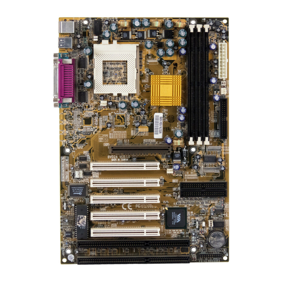
BVD2A Chapter 2 Setup Guide 2.1 Motherboard Layout SOCKET 370 DIMM x 3 T: Mouse B: K/B USB 1/2 ATX Power T: LPT1 B: COM 1/2 VIA Apollo Pro-Plus 133A Chipset FDD Port AGP Slot IDE Port x 2 PCI Slot x 5... -
Page 9: Connector & Jumper Reference
BVD2A 2.2 Connector & Jumper Reference JP17 Socket 370 FAN3 FAN1 AGP SLOT PCI 1 FAN2 PCI 2 IDE 2 SUPER IDE 1 PCI 3 IrDA PCI 4 JBAT1 PCI 5 ISA 1 Battery ISA 2 Connector Front View COM1... -
Page 10: The Setup Steps
BVD2A 2.3 The setup steps refer to the following steps to setup your computer: Refer to the Jumper Setup section to set up the jumpers appropriately. Install the DIMM modules on the motherboard; be sure to install them correctly. III. - Page 11 BVD2A PS/2 Mouse Connector Use this connector to connect a PS/2 Mouse. Description Description Mouse Data N.C. Ground Mouse Clock ATX Power Supply Connector This connector allows the motherboard to draw power from the ATX power supply. We recommend using an ATX power supply with a minimum capacity of 250 watt.
- Page 12 BVD2A Printer Connector This Connector is used for connecting a printer or for transferring data. Signal Name Signal Name Strobe- Data Bit 0 Error Data Bit 1 INIT Data Bit 2 SLCTIN Data Bit 3 Data Bit 4 Data Bit 5...
- Page 13 BVD2A COM1, COM2 –Serial Connectors These connectors are used for connecting a mouse or other serial devices, and are also used to transfer data between peripheral devices. Signal Name Signal Name SOUT USB- Universal Serial Bus (USB1, USB2) Connectors These connectors are commonly used for transferring data between the computer and peripheral devices.
- Page 14 BVD2A IrDA - Infrared Connector: IR This connector is used to connect an infrared device. Signal Name IRRX IRTX WOL – Wake-up On LAN Connector This connector is used to connect an add-in NIC (Network Interface Card). When connected and enabled in the BIOS setup, this function can be used for remotely managing a system on a network.
- Page 15 BVD2A This connector is used to connect an add-in Modem Card. When connected and enabled in the BIOS setup, this function can be used for remotely managing a system on a network. When the Modem controller detects activity on the Modem card, it will consequently wake up the system.
- Page 16 BVD2A JBAT1 – CMOS Clear This jumper can be used to clear the current data stored in the CMOS memory. Description Normal (default) Clear CMOS PANEL CONNECTORS SETTING Locate the bank of switch and indicator connectors. These connectors provide control functions to your system case, such as Speaker, HD LED, Power LED, Key Lock, SMI Switch, Reset…...
- Page 17 BVD2A Name Description 15,17,19,21 SPEAKER Case speaker 20,22 K-LOCK Keyboard Lock 14,16,18 PWR LED Power LED 11,12 ACPI LED ACPI LED 9,10 Reserved Reserved HDD LED Hard Disk LED PWR LED Power LED Reset PWBT Power Button FAN1, FAN2, FAN3 - FAN CONNECTORS These connectors allow the fans of the CPU and the system case to draw power from the motherboard.
- Page 18 CPUs can support all frequencies. Please refer to your CPU specifications before setting the bus speed on your motherboard. The BVD2A will auto-detect your CPU type without your having to set any jumpers. You just need to install your CPU and your system will help you to find the CPU type.
-
Page 19: Memory Installation
BVD2A JP6 - BUS SPEED SETTING CLOCK Auto Short Short 100 MHz Open Short 133 MHz Short Open 2.3-2 Memory installation No jumper changes are necessary for DRAM setting; the system BIOS will check DRAM type and size automatically. This motherboard contains 3 168-pin DIMM sockets (DIMM1, DIMM2, DIMM3). - Page 20 BVD2A already installed. In some cases, there may be a mix of module types. You can confirm this by checking the configuration screen that appears while the computer is starting up. Press the pause key to temporarily interrupt the start-up messages so that you have more time to read the screen. When you’re done, press any key to resume.
- Page 21 BVD2A How to Remove DIMM Modules from Motherboard 1. Press the holding latches at either side of the socket outward to release the DIMM. 2. Gently pull the DIMM out of the socket. Note: Samples of System Memory Combinations Options...
-
Page 22: How To Install The Cpu
Referential Steps of installing the Socket 370 CPU This section is only for CPU installation, the motherboard in the picture is not the BVD2A. Regarding the heat-sink, please refer to the instructions supplied. 1. Review the CPU and motherboard. Socket 370 CPU... - Page 23 BVD2A 3. Locate Pin 1 in the socket and look for the cut edge in the CPU, match Pin 1 with the cut edge then insert the CPU. It should be inserted easily. Cut edge 4. Press the lever down to lock the CPU into the socket.
-
Page 24: Installing The Motherboard
2.3-4 Installing the Motherboard The BVD2A motherboard complies with the specifications for an ATX board, so you can also install this kind of board into a full-size ATX case. Some features on the motherboard are implemented by cabling connectors on the motherboard to indicators and switches on the system case. -
Page 25: Installing An Interface Card
BVD2A 2.3-5 Installing an Interface Card This section explains how to install new interface cards on your motherboard. It covers installing ISA cards, PCI cards and AGP cards. There are seven expansion card slots on the motherboard, one AGP slot, five PCI slots and two ISA slots. -
Page 26: Installing Accessory Cables
BVD2A 2.3-1 Installing Accessory Cables This section describes how to connect the accessory cable that motherboard or system housing supports. In the case of ATX, there is no need to use a bracket to extend the connectors to the rear panel, so here we will discuss only the installation instructions for Floppy, IDE. - Page 27 BVD2A Floppy Cable The floppy cable for floppy disk drives is a 34-pin flat cable with 3 connectors classified as follows: 1. Female header (For floppy connector onboard) 2. Female header and Edge connector (For driver B) 3. Female header and Edge connector (For driver A) The end-most connector cable is twisted to support floppy drive A, while the middle connectors are for floppy drive B.
-
Page 28: Ch3. Award Bios Setup
BVD2A Chapter 3 Award BIOS Setup This chapter explains how to use and modify the BIOS setup utility that is stored on the motherboard. The setup utility stores information about t h e motherboard components, and the configuration of other devices that are connected to it. - Page 29 BVD2A When an option is highlighted, you can execute the option by pressing the Enter key. Some options lead to dialog boxes which ask you to verify that you wish to execute that option. You usually answer these dialogs by typing Y for yes and N for no.
-
Page 30: The Main Menu
BVD2A 3.1 The Main Menu Once you enter the Award BIOS CMOS Setup Utility, the Main Menu appears. Use the arrow keys to select among the items and press the Enter key to accept the current value or enter a sub-menu. - Page 31 BVD2A Standard CMOS Features This setup page includes information on the basic features of your system. Advanced BIOS Features This setup page includes information on some of the more enhanced features of your system. Advanced Chipset Features This setup page includes information on some of the special chipset features.
- Page 32 BVD2A PC Health Status This setup page shows a list of hardware monitoring results. Frequency/Voltage Control This setup page allows you to define clock and system bus speeds. Load Fail-Safe Defaults This page allows you to load the BIOS chipset defaults, indicating the minimum values required by the system for the normal operation.
-
Page 33: Standard Cmos Features
BVD2A 3.2 Standard CMOS Features The Standard CMOS Features page displays a table of items, which are used to define some of the basic features of your system. Date and Time The Date and Time items show the current date and time held by your computer. - Page 34 BVD2A The documentation provided with the drive may not tell you what value to use under the MODE heading. If the drive is smaller than 528 MB, set MODE to Normal. If the drive is larger than 528 MB and it supports Logical Block Addressing, set MODE to LBA- Most high-capacity drives support Logical Block Addressing.
-
Page 35: Advanced Bios Features
BVD2A 3.3 Advanced BIOS Features This option displays a table of items which define more advanced features of your system. Anti-virus Protection Default: Enabled Anti-Virus program can locate and remove problematic programs before any damage is done. When this item is enabled, the Award BIOS will monitor the boot sector and partition table of the hard disk drive at any attempt to modify it. - Page 36 BVD2A Enabled : Activates automatically when the system boots up, if anything attempts to access the boot sector or hard disk partition table, it will cause the above warning message to appear. Disabled : No warning message will appear when anything attempts to access the boot sector or hard disk partition table.
- Page 37 BVD2A Boot Other Device Default: Enabled If you enable this item, the system will search all other possible locations for an operating system if it fails to find one in the devices specified under the first, second and third boot devices.
- Page 38 BVD2A Typematic Rate (Chars/Sec) Default: 6 When the typematic rate is enabled, this section allows you select the rate at which the keys are repeated. 6 characters per second 15 15 characters per second 8 characters per second 20 20 characters per second...
-
Page 39: Advanced Chipset Features
BVD2A Shadow XXXXX-XXXXX Default: Disabled These items allow the BIOS of other devices to be copied to system memory for faster performance. 3.4 Advanced Chipset Features This option displays a table of items, which define timing parameters of the motherboard components including the graphics system, the memory, and the system logic. - Page 40 BVD2A SDRAM Cycle Length Default: 3 This item defines the number of CPU cycles between SDRAM refresh. The refreshment may be not complete and data can be lost when insufficient time is allowed. We recommend that you leave this item at the default value 3.
- Page 41 BVD2A AGP Driving Control Default: Auto This item can be used to signal driving current on AGP cards auto or Manual. Some AGP cards need stronger than normal driving current in order to operate. We recommend that you set this item to Auto by default.
-
Page 42: Integrated Peripherals
BVD2A 3.5 Integrated Peripherals This option displays a list of items which defines the operation of some peripheral items on the system's input/output ports. OnChip IDE Channel0 Default: Enabled OnChip IDE Channel1 Enabled You can use this item to enable or disable the primary and secondary IDE channels that are built into this motherboard. - Page 43 BVD2A Primary Master/Slave PIO Default: Auto Secondary Master/Slave PIO PIO - Programmed Input / Output - allows the BIOS to tell the controller what it wants and then let the controller and the CPU to complete the task by themselves. This is simpler and faster. Your system supports five modes, 0 - 4, which primarily differ in timing.
- Page 44 BVD2A Note: Set to Auto is not recommended. Onboard Serial Port 2 Default: 2F8/IRQ3 User can select serial port IRQ. If set to Auto, system will assign an IRQ for it. Note: Set to Auto is not recommended. UART Mode Select Default: Normal This lets you select the Infrared mode.
- Page 45 BVD2A 3.6 Power Management Setup This option displays a table of items which lets you control the power management of the system. Modern operating systems take care of much of the routine power management. This motherboard supports ACPI (advanced configuration and power interface).
-
Page 46: Power Management
BVD2A ACPI function Default: Enabled When Enabled, this function turns on several power saving measures. Power Management Default: User Define Press Enter to display the Power Management sub-menu. This page allows you to select the type (or degree) of power saving and is directly related to the following modes : Doze;... - Page 47 BVD2A MODEM Use IRQ Default: 3 This item determines the IRQ in which the MODEM can be detected for power management purposes. Choices are: 3,4,5,7,9, 10,11, or N/A. Soft-off by PWR-BTTN Default: Instant-off Under ACPI (advanced configuration and power interface) the system can be turned off mechanically (by the power button) or it can do a software power off.
- Page 48 BVD2A Wake Up on LAN/Ring Default: Disabled If you enable this item, it allows activity on an add-in card in one of the PCI slots to resume the system from a power-saving mode. It will also wakeup the system whenever there is traffic on an installed fax/modem or network adapter.
-
Page 49: Pnp/Pci Configurations
BVD2A 3.7 PnP/PCI Configurations The PnP/PCI Configurations page allows you to configure the ISA and PCI devices installed in your system. The following screen appears if you select the option PnP/PCI Configurations setup option from the main menu. PNP OS Installed... -
Page 50: Pc Health Status
BVD2A Direct Memory Access (DMA) channels. As default, these items are set to PCI/ISA PnP. If you install an ISA Bus card that does not support PNP, and it requires a special IRQ and DMA, you can modify the list of assignments. -
Page 51: Frequency/Voltage Control
BVD2A 3.9 Frequency/Voltage Control This item allows you to set the clock speed and system bus for your system. The clock speed and system bus are determined by the kind of processor you have installed in your system. Auto Detect DIMM/PCI Clk... -
Page 52: Load Fail-Safe Defaults
BVD2A 3.10 Load Fail-Safe Defaults This option opens a dialog box that lets you install fail-safe defaults for all appropriate items in the whole setup utility. Press the Y key and then Enter to install the defaults. Press the N key and then Enter to not install the defaults. -
Page 53: Save And Exit Setup
BVD2A 4. The system will ask you to confirm the new password by asking you to type it in a second time, Carefully type the password again and press Enter, or just press Enter if you are deleting a password that is already installed. -
Page 54: Ch4. Software Setup
BVD2A Chapter 4 Software Setup The support software for this motherboard may be supplied on either a CD-ROM, or on one or more diskettes. All the support programs are stored in separate folders, so you can find the program you need easily. The support software provided contains the following programs: IDE Bus Master drivers for Win 95/NT. - Page 55 BVD2A 3. Press “VIA APOLLO PRO/Plus” button. VIA APLLLO PRO/Plus button 4. Then you will see the dialog box as following: You just click the “1. VIA Driver Install” item and follow the instructions to setup these software. 5. Follow the instructions to complete the software installation, then re-boot your PC.
Need help?
Do you have a question about the BVD2A and is the answer not in the manual?
Questions and answers