Table of Contents
Advertisement
Contents
CH1. MOTHEROARD FEATURE .............................................................1
!SPECIFICATIONS ..........................................................................1
!POWER OFF CONTROL SOFTWARE .........................................3
!PACKAGING CHECK LIST ..........................................................3
CH2. SETUP GUIDE.....................................................................................4
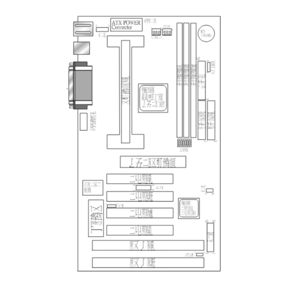
!MAINBOARD LAYOUT DRAWING............................................4
!JUMPER & CONNECTOR SETTING ...........................................6
CONNECTOR SETTING ...............................................................6
JP3 OTHER JUMPER SETTING ..................................................9
CPU TYPE SELECT ....................................................................10
FAN CONNECTOR......................................................................15
!MEMORY INSTALLATION........................................................16
CH3. AWARD BIOS SETUP......................................................................17
!THE MAIN MENU .......................................................................19
!STANDARD CMOS SETUP.........................................................21
!BIOS FEATURES SETUP ............................................................22
!CHIPSET FEATURES SETUP .....................................................28
!POWER MANAGEMENT ............................................................29
!PNP / PCI CONFIGURATION SETUP ........................................34
!INTEGRATED PERIPHERALS ...................................................36
!LOAD BIOS DEFAULT ...............................................................37
!LOAD SETUP DEFAULT ............................................................37
!SUPERVISOR / USER PASSWORD SETTING..........................37
!IDE HDD AUTO DETECTION....................................................38
CH4. WINBOM W83781D SETUP GUIDE..............................................39
®
✒ PENTIUM
II CPU INSTALLATION GUIDE... ... .... ... ... ... ... ... .. 42
REMARK
®
INTEL
is a registered trademark of Intel Corporation.
All other brands and product names are trademarks registered trademarks of their
respective companies.
CONTENTS
i
Advertisement
Table of Contents

Related Manuals for Procomp B683


Summary of Contents for Procomp B683
-
Page 1: Table Of Contents
Contents CONTENTS CH1. MOTHEROARD FEATURE .............1 !SPECIFICATIONS ................1 !POWER OFF CONTROL SOFTWARE .........3 !PACKAGING CHECK LIST ............3 CH2. SETUP GUIDE..................4 !MAINBOARD LAYOUT DRAWING..........4 !JUMPER & CONNECTOR SETTING ...........6 CONNECTOR SETTING ...............6 JP3 OTHER JUMPER SETTING ..........9 CPU TYPE SELECT ..............10 FAN CONNECTOR..............15 !MEMORY INSTALLATION............16 CH3. -
Page 2: Specifications
B683/B680 Chapter 1 Motherboard Feature SPECIFICATIONS ® Intel 440BX chipset, Winbond 83977TF-AW System Chipset ® Pentium 66/100 MHz CPU CPU Bus Speed 200MHz ~ 550MHz CPU Clock Expandable to 384MB(3 banks) with 168-Pin Memory Subsystem SDRAM(DIMM) Socket X3 Two high speed 16550 compatible serial ports, one... - Page 3 CPU Fan Control ( the fan will automatically stop when the system enters suspend mode) On-Board W83781D CPU Overheat Warning(reserved) (Only for B683) Chassis Intrusion Detect (reserved) Display Actual Current Voltage Four PCI Master Slots & Two 16-bit ISA Slots Expansion slot Support 3.3/5V PCI bus Interface...
-
Page 4: Power Off Control Software
The motherboard comes securely packed in a durable box and shipping carton. If any of the above items are missing or damaged , please contact your supplier. The motherboard contains: Q’ TY Description motherboard : B683/B680 Diskette : Bus master driver Award system BIOS Cable : Enhanced IDE connector Cable : F.D.D connector... - Page 5 B683/B680 Chapter 2 SETUP GUIDE B683 Motherboard Layout Drawing...
- Page 6 B683/B680 B680 Motherboard Layout Drawing...
-
Page 7: Jumper & Connector Setting
B683/B680 JUMPER & CONNECTOR SETTING Connector Setting KB1- PS/2 Keyboard/ PS/2 Mouse Connector Description Keyboard Data 2 , 6 N.C. Ground Keyboard Clock Description Mouse Data 2 , 6 N.C. Ground Mouse Clock USB1-Universal Series Bus (USB) Connectors USB1 Pin... - Page 8 B683/B680 JWR1 - Power Supply Connector Description 1,2,11 + 3.3 V 3,5,7,13,15,16,17 Ground 4,6,19,20 + 5 V POWER GOOD 5VSB +12 V -12 V PS-ON - 5 V JP2 – Infrared Connector : IR Signal Name SIRRX IRTX JBAT1 – CMOS CLEAR...
- Page 9 B683/B680 LPT1- PRINTER Connector Signal Name Signal Name Strobe- Data Bit 0 Error Data Bit 1 INIT Data Bit 2 SLCTIN Data Bit 3 Data Bit 4 Data Bit 5 Data Bit 6 Data Bit 7 Busy SLCT COM1,COM2 - Serial Connectors...
-
Page 10: Jp3 Other Jumper Setting
B683/B680 Note : 1-2 Disabled (Default) 2-3 Enabled JSB1 – For Sideband Signals Connector Ex. Creative SB-LINK Connector Signal Name -GNTA -REQA SERIRQ JP3 – OTHER JUMPER SETTING Power_LED KEY_Lock HDD_LED SUS_LED Reset EXT_SMI Name Description 1 - 3 Reset... - Page 11 B683/B680 JP1 - POWER BUTTON Description ON/OFF...
-
Page 12: Cpu Type Select
B683/B680 CPU TYPE Select CPU Bus Speed - 66MHz part : 1. 200MHz SW1-1 SW1-2 SW1-3 SW1-4 SW1-5 SW1-6 CT S 208-6 T 808 2. 233MHz SW1-1 SW1-2 SW1-3 SW1-4 SW1-5 SW1-6 CT S 208-6 T 808 3. 266MHz SW1-1 SW1-2 SW1-3 SW1-4 SW1-5 SW1-6... - Page 13 B683/B680 5. 333MHz SW1-1 SW1-2 SW1-3 SW1-4 SW1-5 SW1-6 CT S 208-6 T 808 CT S 208-6 T 808 6. 366MHz SW1-1 SW1-2 SW1-3 SW1-4 SW1-5 SW1-6 CT S 208-6 T 808 CT S 208-6 T 808 7. 400MHz SW1-1 SW1-2 SW1-3 SW1-4 SW1-5 SW1-6 8.
- Page 14 B683/B680 9. 466MHz SW1-1 SW1-2 SW1-3 SW1-4 SW1-5 SW1-6 CT S 208-6 T 808 CT S 208-6 T 808 10. 500MHz SW1-1 SW1-2 SW1-3 SW1-4 SW1-5 SW1-6 CT S 208-6 T 808 CT S 208-6 T 808...
- Page 15 B683/B680 CPU Bus Speed - 100MHz part : 1. 300MHz SW1-1 SW1-2 SW1-3 SW1-4 SW1-5 SW1-6 CT S 208-6 T 808 CT S 208-6 T 808 2. 350MHz SW1-1 SW1-2 SW1-3 SW1-4 SW1-5 SW1-6 CT S 208-6 T 808 CT S 208-6 T 808 3.
- Page 16 B683/B680 5. 500MHz SW1-1 SW1-2 SW1-3 SW1-4 SW1-5 SW1-6 CT S 208-6 T 808 CT S 208-6 T 808 6. 550MHz SW1-1 SW1-2 SW1-3 SW1-4 SW1-5 SW1-6 CT S 208-6 T 808 CT S 208-6 T 808...
-
Page 17: Fan Connector
B683/B680 CPU TYPE SELECT LIST SW1-1,2,3,4 (For RATIO select) RATIO SW1-1 SW1-2 SW1-3 SW1-4 SW1-5 (For BUS clock) CLOCK SW1-5 66 MHz 100 MHz SW1-6 (CPU BUS Clock manual / Auto detect) CLOCK SW1-6 Default (Auto Detect) Force BUS CLOCK up to 100 MHz... -
Page 18: Memory Installation
MEMORY INSTALLATION No jumper setting is necessary for DRAM setting, BIOS will check DRAM type and size automatically. B683 motherboard contains 3 by 168-pin DIMM sockets(DIMM1,DIMM2,DIMM3). B683 motherboard has table-free ( or auto-bank ) feature and user can install DIMM into any bank. -
Page 19: Ch3. Award Bios Setup
B683/B680 Chapter 3 AWARD BIOS SETUP Award BIOS ROM has a built-in Setup program that allows users to modify the basic system configuration. This type information is stored in battery-backed RAM so that it retains the Setup information when the power is turned off. - Page 20 B683/B680 Right Arrow Move to the item in the right hand Esc Key Main Menu Quit and not to save changes to CMOS Status Page setup menu and Option Page Setup Menu Exit current page and return to Main Menu...
-
Page 21: The Main Menu
B683/B680 The Main Menu Once you enter Award BIOS CMOS Setup Utility, the Main Menu will appear on the Screen.. Use arrow keys to select among the items and press to accept or enter the sub-menu. ROM PC/ISA BIOS (2A69KPNJ) CMOS SETUP UTILITY AWARD SOFTWARE, INC. - Page 22 B683/B680 PNP / PCI CONFIGURATION SETUP This menu allows the user to modify PNP / PCI configuration function. Load BIOS Defaults BIOS defaults indicates the most appropriate value of the system parameter which the system would be in minimum performance.
-
Page 23: Standard Cmos Setup
B683/B680 ON NOW FUNCTION User can select the way to power on system from BIOS Setup. Choose “ Integrated Peripheral “ item , user can setup “ POWER ON FUNCTION” BUTTON ONLY: Power on by power button only. PASSORD: Select “ KB Power on Password” then enter. Key in password and save CMOS SETUP. -
Page 24: Bios Features Setup
B683/B680 BIOS Features Setup ROM PCI/ISA BIOS (2A69KPNJ) BIOS FEATURE SETUP AWARD SOFTWARE, INC Anti-Virus Protection : Enabled Video BIOS Shadow : Enabled CPU Internal Cache : Enabled C8000-CBFFF Shadow : Disabled External Cache : Enabled CC000-CFFFF Shadow : Disabled... - Page 25 B683/B680 Enabled Activate automatically when the system boots up causing a warning message to appear when anything attempts to access the boot sector or hard disk partition table. Disabled No warning message to appear when anything attempt to access the boot sector or hard disk partition table.
- Page 26 B683/B680 C,A,SCSI/ D,A,SCSI/ E,A,SCSI/ F,A,SCSI: System will first search for IDE hard disk driver ( C: D: or E: or F:) then second search floppy disk driver then SCSI hard disk driver. SCSI,A,C: System will first search SCSI hard disk driver then second search for floppy disk driver then IDE hard disk driver.
- Page 27 B683/B680 Boot Up NumLock Status The default value is On. Keypad is number keys Off: Keypad is arrow keys Boot Up System Speed It selects the default system speed - the speed that the system will run at immediately after power up.
- Page 28 B683/B680 : 12 characters per second : 15 characters per second : 20 characters per second : 24 characters per second : 30 characters per second Typematic Delay (Msec) When holding the a key, the time between the first and second character will be displayed.
- Page 29 B683/B680 Video BIOS Shadow It determines whether video BIOS will be copied to RAM, however, it is optional from chipset design. Video shadow will increase the video speed. Enabled: Video shadow is enabled Disabled: Video shadow is disabled C8000-CBFFF Shadow/DC000-DFFFF Shadow These categories determine whether optional ROM will be copied to RAM by 16K byte.
-
Page 30: Chipset Features Setup
Unless you are a qualified engineer & know the items, functions you are going to modify. We do not recommend you to change the default setting. Note: Above “CHIPSET FEATURE SETUP” referential list is for B683, if your motherboard is B680, the sensor part will be not display. -
Page 31: Power Management
B683/B680 Power Management ROM PCI/ISA BIOS (2A69KPNJ) POWER MANAGEMENT SETUP AWARD SOFTWARE, INC. ACPI function : Enabled ** Reload Global Timer Events ** Power Management : User Define IRQ [3-7,9-15],NMI : Disabled PM Control by APM : Yes Primary IDE 0... - Page 32 B683/B680 Item Options Descriptions A. Power Management 1. Disable Global Power Management will be disabled 2. User Define Users can configure their own power management 3. Min Saving Pre-defined timer values are used such that all timers are in their MAX value 4.
- Page 33 B683/B680 Item Options Descriptions D. Video off Method 1. Blank Screen The system BIOS will only blanks off the screen when disabling video 2. V/H SYN In addition to (1), BIOS will C+Blank also turn off the V-SYNC & H-SYNC signals form VGA cards to monitor E.
- Page 34 B683/B680 Item Options Descriptions G. Doze Mode Disable System will never enter (*) Remark 1 DOZE mode 1 Min Defines the continuous idle 2 Min time before the system 4 Min entering DOZE mode. 8 Min 12 Min If any item defined in (J) is 20 Min enabled &...
- Page 35 B683/B680 Normally, STANDBY mode puts the system into low speed or 8, screen may be off depend on (E) Item Options Descriptions I. Suspend Mode 1. Disable System will never enter (*) Remark 1 SUSPEND mode Defines the continuous idle...
-
Page 36: Pnp / Pci Configuration Setup
B683/B680 PNP / PCI Configuration Setup ROM PCI/ISA BIOS(2A69KPNJ) PNP/PCI CONFIGURATION AWARD SOFTWARE, INC. PNP OS Installed : No PCI IDE IRQ Map To : PCI-AUTO Resources Contorlled By : Manual Primary IDE INT# Reset Configuration Data : Disabled Secondary IDE INT#... - Page 37 B683/B680 Item Options Descriptions A. PCI IDE IRQ Map To PCI-AUTO PCI-AUTO PCI-SLOT1 The BIOS will: PCI-SLOT2 − scan for PCI IDE devices & determine the location of the PCI IDE device PCI-AUTO PCI-SLOT1 PCI-SLOT1 PCI-SLOT2 PCI-SLOT2 − assign IRQ 14 for primary IDE INT# IRQ...
-
Page 38: Integrated Peripherals
B683/B680 INTEGRATED PERIPHERALS ROM PC/ISA BIOS(2A69KPNJ) INTEGRATED PERIPHERALS AWARD SOFTWARE, INC. IDE HDD Block Mode : Enabled Onboard Serial Port 1 : 3F8/IRQ4 IDE Primary Master PIO : Auto Onboard Serial Port 2 : 2F8/IRQ3 IDE Primary Slave PIO : Auto... -
Page 39: Load Bios Default
B683/B680 Load BIOS Default When you access "Load BIOS Default", the following message appears: Load BIOS Default (Y/N) ?N The BIOS Default values are the "worst case" default, and are the most stable values for the system. Use them if the system is performing erratically due to hardware problems. -
Page 40: Ide Hdd Auto Detection
B683/B680 IDE HDD Auto Detection This feature allows you to check all the informations on your hard disk formation. When you access "IDE HDD Auto Detection", the system executes auto detection. At the prompt, it represents all the informations on your HDD, and you are... - Page 41 B683/B680 Chapter 4 Winbond W83781D Setup Guide This part only for B683 The W83781D supports 3 Temperature Resister Sensors , voltage detection, fan speed sensor control. 3 Temperature Resister Sensors: a. RT2: This function is the CPU’ s temperature sensor.
- Page 42 B683/B680 Winbond 83781D Fan Application ♦ Voltage default - The Application of W83781D also controls the fan speed. The default of CPU Fan, SYS1 Fan and SYS2 Fan is “Enable”. ♦ When you connect just only one CPU Fan -...
- Page 43 B683/B680 2. Click the “ Disable” of the warning icon of Fan 3, then it shows the warning icon of Fan 2. You just click the “ Disable” icon as previous step. Then “ Save” and “ Exit” . The correct setup is completed.
- Page 44 B683/B680 How to install the CPU Prepare the motherboard by installing the supplied Slot 1 CPU, then install the CPU according to the instructions supplied. Complete the processor installation by installing the supplied heat-sink support, and connecting the heat sink power cable to the motherboard connector.
- Page 45 B683/B680 3. Once the above two steps have been completed, slot the CPU Retention into Slot1. Pull up the CPU stays on both side of the CPU Retention so they are horizontal, at an angle of 90°. Then the side of the CPU Retention with no mark on it and the side of Slot1 with the small rectangular tab should be on the same side.
- Page 46 B683/B680 5. Slide the CPU slowly into Slot1 along the two sides of the CPU Retention. Note: Some Slot 1 processors with different packing maybe need the caps to let them be fixed. So if it need the caps during installing Slot 1 CPU, please follow this step: “...
- Page 47 B683/B680 SLOT 1 CPU Disassembly/Replacement Procedures 1. Move the protruding part on top of the CPU locking caps gently outwards, so that the locking caps come off. 2. Pull the CPU Fan connector off the motherboard, and then gently pull the CPU out from Slot1.
- Page 48 B683/B680...
Need help?
Do you have a question about the B683 and is the answer not in the manual?
Questions and answers