
Related Manuals for Proceq ZDR 6020


Summary of Contents for Proceq ZDR 6020
- Page 1 ZDR 6020 Dynamic Retroreflectometer R for the following versions 6020.EU.1m and 6020.OV.1m Instruction Manual...
-
Page 3: Table Of Contents
Index Exclusion of liability ........... Error! Bookmark not defined. 1 Description of device ...................7 2 Safety information ....................9 2.1 Symbols used ....................9 2.2 Safety notes and hints ...................9 3 Delivery of device ....................10 3.1 Damages during carriage ................10 3.2 Shipment ..................... - Page 4 5.5.1 Project ....................30 5.5.2 Measuring file ..................30 5.5.3 Measuring file format ................. 32 5.6 Calibrate ..................... 34 5.6.1 Calibrate measuring head ..............34 5.6.2 Speed calibration ................35 5.7 Camera ....................... 36 5.7.1 Camera properties ................36 5.8 Settings ....................... 37 5.8.1 Marking presettings ................
- Page 5 10.3 Replacing the lamp ..................60 10.4 Replacing the protective glass ..............65 10.5 Replacing the fuse ..................65 11 Error messages ....................66 12 Technical specification ..................67 Glossary ........................69 Page 5...
-
Page 6: Exclusion Of Liability
Illustrations, descriptions as well as the technical specifications conform to the instruction manual on hand at the time of publishing or printing. However, Proceq SA policy is one of continuous product development. All changes resulting from technical progress, modified construction or similar are reserved without obligation for Proceq SA to update. -
Page 7: Description Of Device
Description of device The ZDR 6020 is a vehicle mounted mobile retro-reflectometer with 300 measurements per second guaranteeing accurate and continuous coverage of the night visibility (R ) of all types and colours of road markings. A measuring head can be mounted on either side of the measuring vehicle, which... - Page 8 • Approved by the accredited association StrAus-Zert, Germany (test No. 0913- 2009-05). Measuring principle: The ZDR 6020 Dynamic Retro-reflectometer R measures the Retroreflection of road markings true to scale. is the coefficient of retroreflected luminance (night visibility) of road markings.
-
Page 9: Safety Information
2.2 Safety notes and hints The ZDR 6020 is a high quality, state of the art instrument and is safe to operate. Nevertheless, there is always risk when the instrument is handled inappropriately. -
Page 10: Delivery Of Device
All maintenance and repair work which is not explicitly allowed and described in this manual (see chapter 10.1 “Maintenance carried out by the user” on page 60) shall only be carried out by Proceq SA or your authorized Proceq agent, failure to comply voids warranty. -
Page 11: Shipment
7 days. However, this period may vary depending on the courier. Hence, it is recommended to check the exact time limit when receiving the goods. If there are any damages also inform your authorized Proceq agent or Proceq SA immediately. 3.2 Shipment Should the device be transported again, it must be packaged properly. -
Page 12: Standard Delivery
3.3 Standard delivery Following parts are included in the delivery: ZDR 6020 1 m Measuring head Removable sunshade Mounting adapters (left/right) for measuring head mounting Ruggedized touchscreen tablet with installed ZDR 6020 “RetroGrabber software and microphone Tablet docking station Tablet mount... - Page 13 Power supply unit (car box) Storage box Gauge Auxiliary height indicators Set of tools • 6 Allen keys (1.5 mm, 2 mm, 2.5 mm, 3 mm, 4 mm, 5 mm) • 1 Allen screw M4 • 2 Spanner wrenches (10 mm, 19 mm – 1 each) •...
-
Page 14: Options
• ZRM 6006 Retro-reflectometer R All spare parts can be purchased from Proceq or an authorized agent. Proceq SA refuses all warranty and liability claims for damages caused by usage of the ZDR 6020 in combination with non-original accessories, or accessories from 3 party suppliers. -
Page 15: System Components
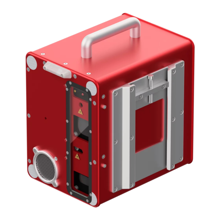
System components 4.1 General overview The ZDR 6020 Dynamic Retroreflectometer R consists of several components that are necessary for the operation. These components are described in the following chapters: • Measuring head • External connectors • Carrier pipe • Tablet, docking station and tablet mount •... - Page 16 4.2 Measuring head The measuring head is designed to be mounted on either side of the measuring vehicle or on a stationary test stand. A real-time computer inside the measuring head controls and monitors the data acquisition process. Furthermore, it streams the measured values to the RetroGrabber software on the tablet.
- Page 17 Connector plug Handle Height adjustment screw Mounting bracket Keep the device dry. Danger of short circuit! 4.3 External connectors The measuring head is connected to the system by a heavy duty industrial plug connector. They are located next to the rear wheel on either side of the measuring vehicle, see picture below.
- Page 18 Fasteners Quick release 4.5 Tablet, docking station and tablet mount A ruggedized touchscreen tablet is used to operate the ZDR 6020. With the installed RetroGrabber software, it communicates with the measuring head and records measured data to its hard drive.
- Page 19 Tablet Docking station Tablet mount Co-driver seat Two cables are plugged into the docking station: Ethernet connector Power docking station When driving with the tablet mount in place, the passenger side airbag should be deactivated. It is forbidden to operate the vehicle with a person seated in the passenger seat while the tablet mount is in use.
-
Page 20: Camera
4.6 Camera The ZDR 6020 is equipped with an auto-iris camera mounted on the windscreen with vacuum cup. It records a picture of the road ahead and its markings every 10 m. While measuring it is also possible to have a live image displayed by pressing the button “Camera”... -
Page 21: Panel Switches
The lasers are only powered on when the measuring head switch is on as well. The ZDR 6020 consumes a lot of power during operation. It is therefore essential that the car engine is always running while the system is switched Laser radiation class 2. -
Page 22: Calibration Unit
4.8 Storage box The grey storage box sits in a black aluminium frame which is usually located in the car trunk. It contains the measuring head, the mounting adapters, all tools and spare parts. Storage box Black aluminium frame Calibration unit Power supply unit (car box) Auxiliary height indicators Sunshade... - Page 23 4.9 Power supply unit (car box) The power supply unit (car box) is usually located in the car trunk below the grey storage box, see pictures in chapter 4.8 “Storage box” on page 22. It is the central wiring point connecting different components of the system. Most fuses are located in the power supply unit (car box).
-
Page 24: Wiring
4.11 Wiring The wiring between the different system components is installed once and is invisible to the user. Most cables go to the power supply unit (car box) and don’t need to be manipulated for normal measuring operation. Wiring schematics: Page 24... -
Page 25: Retrograbber Software
RetroGrabber Software The RetroGrabber software is needed to operate the ZDR 6020 Dynamic Retro- reflectometer R . It performs the following operations: • Obtaining the measurements from the measuring head • Calculating an average value of all received sensor signals •... - Page 26 5.3.2 Main menu The main menu is located on the left side of the main screen. It contains seven different buttons: Measure: Measuring mode Project: Create and open projects and measuring files Calibrate: Calibration of measuring head, speed calibration Camera: Camera settings Settings: System configuration, filter settings, marking presettings...
-
Page 27: Measure
5.4 Measure By clicking on “Measure” in the main menu, the measuring window is displayed, which is also RetroGrabber’s default window. 5.4.1 Measuring window If the measuring head has not established a connection to the RetroGrabber software (icon in the status bar is dark green), a black window is displayed: As soon as the measuring head has established a connection to the RetroGrabber software (icon in the status bar is light green), the measuring window appears. - Page 28 As neither a project nor a measuring file have been opened yet, no data will be stored on the tablet and only a limited number of features are displayed in the measuring window. For a detailed explanation of all available features in the measuring window, please see below.
-
Page 29: Project
Bar diagram: The bar diagram represents the road ahead and its markings. Up to three markings can be detected and displayed simultaneously. The width of the bar depends on the width of the marking and on the filter settings. To distinguish between the markings, they are displayed in different colours: •... -
Page 30: Project
5.5.1 Project A project is a container for measuring files, pictures and voice recordings. By clicking on “Project” in the main menu, the project window is displayed. Create: Opens a file explorer window. Browse to the appropriate folder location and enter a project name to create a new project. - Page 31 Measurements: List with all measuring files from the current project New: Opens an editor mask with file header information, see picture below: Measurement Name: Filename, compulsory Region: Measuring area, optional Street: Street name, optional Lane: Lane name, optional Start Position: Start position (km) of measurement, default = 0 Side: Lane position, optional...
-
Page 32: Measuring File Format
Opens a file explorer window in the current project folder 5.5.3 Measuring file format The measuring file generated by the ZDR 6020 is stored in an open source, tab separated text file. Even though it has an “.xls” file ending, it can be opened and altered with any text editor like Notepad. - Page 33 ⋅lx Max: The maximum R value in [mcd⋅m ] over the last interval Std Dev: Standard deviation (type: population) of R during the interval % Pass: Percentage of values that have passed the data process filters. A high value means high signal quality. Day contrast ratio Marker: Event buttons pressed...
-
Page 34: Calibrate
5.6 Calibrate 5.6.1 Calibrate measuring head The ZDR 6020 should be levelled and calibrated every time it is mounted on the vehicle. Click on “Calibrate” in the main menu to open the calibration window: Calibrate: Bar diagram ⋅lx Calibration Standard: R value in [mcd⋅m... -
Page 35: Speed Calibration
5.6.2 Speed calibration The ZDR 6020 takes the speed information from an adapter connected to the internal car communication system (CAN bus). The extracted signal is proportional to the vehicle speed and needs to be calibrated for proper mileage calculation. -
Page 36: Camera
5.7 Camera The camera is mounted on a vacuum cup on the windscreen and takes pictures of the road ahead as seen by the driver. This allows visual control of the road markings. The system is configured to take a picture every 10 meters. Click on “Camera”... -
Page 37: Settings
5.8 Settings A multitude of settings can be adjusted in the settings window. Click on “Settings” in the main menu to open the settings window: 5.8.1 Marking presettings Marking presettings are used to store measurement parameters for a marking. The marking presettings can be prepared in the office before measuring and then be applied on site. -
Page 38: General Settings
Settings Name: Name of the marking presetting Trigger Mode: Automatic Meters (distance based, default) or Automatic Seconds (time based for stationary wet measurements). Indicates the distance or time interval for calculating the average R value in the measurement file Average every: Interval length (meter or seconds), depending on the trigger mode. -
Page 39: Event Button Configuration
GPS Precision: 12 (default) Convert to old Format: Converts measurement files to old format See chapter 9 “Data analysis” on page 59. 5.8.3 Event button configuration The buttons underneath the bar diagram in the measuring window are called “Event Buttons”, see chapter 5.4.1 on page 27. They store predefined texts in the measuring file when pressed during a measurement. - Page 40 Cameras: Cameras connected to the system Enable Pictures: Enable / disable camera Take Pic every full km: Automatically takes several pictures every km. This is meant to detect position indicators on the road and adjust the mileage accordingly Take always Pictures: Takes pictures every 10 m Apply Marking Presetting: Takes a picture if the R value is below or above...
-
Page 41: Bar Graph Settings
5.8.5 Bar Graph settings The bars in the bar diagram can be configured in the “Bar Graph Settings“. Show simplified Bar-graph: Bar in the bar graph is rectangular Show grey Bars on Bar-graph: Hides bars that are not recognized as markings 5.8.6 System configuration There is no need to change the settings in this window for normal operation. - Page 42 Filter Settings: Data filter needed to calculate R Live Data Monitor: Internal use only DB Data Monitor: Internal use only Msre & RT Monitor: Important system parameters like lamp voltage Connection Monitor: Information about TCP parameters and active connection. Calibration Monitor: Calibration parameters, internal use only GPS Monitor: GPS, temperature and humidity...
- Page 43 Edit Filter Settings: Enable editing filter settings PassFailFilterSettings Upper and lower limit for valid R values. Taken from the current Marking Presetting, see chapter 5.8.1 on page 37. Values outside of limits are discarded. • PassFail: Enable / disable filter •...
- Page 44 No. of Markings Filter Number of expected markings, value taken from the current Marking Preset, see chapter 5.8.1 on page 37. Default = 1 DayContrastFilter Calculation of day contrast ratio. • DayContrast: Enable / disable filter • ToleranceBandFromB.: Tolerance band in %, default = 10 Contrast Filter Calculation of day contrast ratio.
-
Page 45: Admin
LampVoltageMeasured: Voltage on halogen lamp Speed km/h: Vehicle speed 5.8.7 Admin Password protected administration area, for internal use only. 5.9 Info Errors, warnings and general system information. Click on “Info” in the main menu to open the info window. 5.9.1 Messages Errors and messages are displayed and explained in this area. -
Page 46: System Info
5.9.2 System info Host Address: IP of RetroGrabber Last R Calibration: Date of last calibration RetroGrabber Version: RetroGrabber software version Serial Number: Serial number of measuring head Target Address: IP of measuring head Measuring head Version: Measuring head hardware version Realtime Version: Measuring head software version Measuring... -
Page 47: Country Regulations
6.1 Country regulations Please take into consideration that several countries have certain regulations concerning the measurement of road markings. Please inform yourself before starting to measure in order to comply with these regulations. 6.2 Setting up the system Preparing the system for measuring involves placing the tablet in the docking station, starting the RetroGrabber software and attaching and levelling the measuring head. - Page 48 Main switch Switch on the tablet. Mount the measuring head while the tablet is booting up: Open the fasteners and remove the protective cap from the carrier pipe. Open the protective cap on the external connector by pushing back the safety clamp underneath. Slide the mounting adapter with the nozzle on top into the carrier pipe.
- Page 49 Plug in the connector. Secure the connector by locking the safety clamp. Use the screwdriver type #5 Allen key to lock the quick release fastener. Quick release fastener locked. Start the RetroGrabber software then switch on “Head” on the panel and wait approx.
- Page 50 Head switch Measuring head connected to RetroGrabber software (icon light green) Switch on “Laser” on the panel: Laser switch. Laser radiation class 2. Avoid direct eye contact to beam. Place the corresponding auxiliary height indicator next to the centre of the front and rear wheel, so that the laser beams are visible: Auxiliary height indicators The height indicator for the front...
- Page 51 Use the height adjustment screw on the measuring head and the angle adjustment screw on the mounting adapter to level the measuring head in a way that both laser beams point to the white ring on the auxiliary height indicators: Height adjustment screw on the measuring head Use the screwdriver type #5 Allen...
-
Page 52: Calibration
6.3 Calibration Each time the measuring head is mounted on the vehicle it should be calibrated, at least once a day. Calibration means that the ZDR 6020 is compared to a reference calibration standard with a known R value. The deviation between the measured and the reference values should not exceed 5 %. - Page 53 Insert the cover plate into the two holes at the far end of the calibration unit. Make sure the plate is correctly seated. The yellow mark must be in level with the calibration unit. Adjust position and height of the calibration units´...
- Page 54 Properly placed calibration unit Open the calibration dialog in the RetroGrabber software. Make sure that “R Calibration Standard” is the reference value of the calibration unit. Change that value in the Setup if necessary. Press Calibrate. The calibration process takes a couple of seconds.
-
Page 55: Measuring
6.4 Measuring Measuring is done by driving along the road and scanning the road pavement markings with the measuring head. In the driver display you will see the red, green and blue sensor bars that represent the markings. While driving, always make sure the markings are inside the detection area. - Page 56 Open or create a project Open or create a measuring file Open the measuring window. All icons in the status bar are now light green and the system is ready for measuring Having reached the point where you want to start to measure, press “Capture” and the software will then record the measurement information on the tablet.
-
Page 57: Speed Calibration
Speed Calibration The speed is calculated from the car’s odometer pulse and needs to be calibrated by the RetroGrabber software. After the initial factory calibration it is only necessary to do a speed calibration when changing tires, e.g. changing from summer to winter tires. -
Page 58: Tools
The measuring head will not connect when NetSetMan is set to Office. Do not forget to switch to ZDR 6020 profile before setting up the system. 8.2 LogMeIn The program LogMeIn allows remote access to the tablet. This feature is used by Zehntner for maintenance purposes such as software updates or trouble shooting. -
Page 59: Data Analysis
Choose the appropriate ZDR 6020 measuring file “xxx.xls” from the explorer window. Now there are three files called xxx_converted_1.xls, xxx_converted_2.xls and xxx_converted_3.xls which can be imported in the “MappingTools” software. The new version of “MappingTools” (1.26 and higher) can import all ZDR 6020 measuring files without prior conversion. Page 59... -
Page 60: Maintenance
All other maintenance and repair work may only be carried out by Proceq SA Instruments or your authorized Proceq agent, otherwise all warranty is void. Make sure that the ZDR 6020 is turned off and unplugged before doing any maintenance. - Page 61 Note: The spare lamps are aligned optically and then glued to the lamp holder part. This alignment process may only be performed at Proceq SA Factory. Open the measuring head housing: Loosen the three screws on the right side of the cable on the back side (Allen key 2 mm).
- Page 62 Place both hands on each side of the measuring head as shown in the picture. The thumb against the edge of the mounting bracket and all other fingers against the small edge of the back plate. Press on both sides simultaneously. Press with the thumb forward against the mounting bracket and pull back the back plate with all other fingers.
- Page 63 Loosen the two screws on the lamp holder with a 3mm Allen key. Lift up the air outlet part a little, and then push back the air outlet part by squeezing the flexible tube together. When the flexible tube is squeezed, the lamp with its holder is laid open.
- Page 64 Put back the lamp to its position carefully. Always make sure it sits nice and tight in its fit. For easier operation it is recommended to remove the screws before positioning the lamp. Afterwards place the air outlet part into its position.
-
Page 65: Replacing The Protective Glass
10.4 Replacing the protective glass Open the twelve Allen screws with the 2 mm Allen key and remove the black cover. Replace the safety glass and gently screw the black cover back on. Do not overtighten the screws as the protective glass might crack. 10.5 Replacing the fuse There is a set of spare fuses to be found in the grey storage box. -
Page 66: Error Messages
Restart the system. 7110 Unable to Make sure the current NetSetMan profile Measuring head not connect to the is set to ZDR 6020. Restart the system. connected measuring head Check the LEDs at the network plug of the docking station. 7210... -
Page 67: Technical Specification
box). 7516 No connection Check GPS settings and network GPS Trimble to GPS receiver connection. Settings available 7530 Camera not Make sure the camera is connected Camera error connected correctly. 7531 No camera Make sure the camera is connected Camera error available correctly. - Page 68 ≥ 1000 mm x 880 mm (≥39.4“ x 34.65“) Measuring area (WxL): Measuring distance: 6 m (19.7 ft.) Measuring speed: max. 150 km/h (93.21 mph) 0 - 4‘000 mcd⋅m ⋅lx Measuring range R profiled markings -≈20 mm (0.79") Power consumption: 12 - 16VDC;...
-
Page 69: Glossary
Glossary Admin ..........45 General overview ......15 Apparatus Specifications ......68 Info ..........45 Instrument Bar Graph settings ......41 Delivery ........10 Description ........7 Extent of delivery ......12 Calibrate ........34 Calibration ........52 Calibrating speed ....... 57 Lamp Calibration unit ...... - Page 70 Replacing ........65 Speed Calibration ......57 Standard delivery ......12 Storage Temperature ......68 Replacing Storage box........22 Fuse ........... 65 System components ..... 15 Lamp .......... 61 System configuration ....41 Protective glass......65 System info ........46 RetroGrabber Software ....
- Page 72 Subject to change. Copyright © 2017 by Proceq SA, Schwerzenbach. All rights reserved. www.proceq.com Version 2.6 dated 15.06.2017...
Need help?
Do you have a question about the ZDR 6020 and is the answer not in the manual?
Questions and answers