Table of Contents
Advertisement
Quick Links
Advertisement
Table of Contents

Related Manuals for Proceq Zonotip


Summary of Contents for Proceq Zonotip
- Page 1 Operating Instructions Thickness Gauge Made in Switzerland...
-
Page 2: Table Of Contents
4.3.1 Create a New Material / Edit a Material 4.3.2 Calibration on known Material / Determinate the US velocity 4.3.3 Overview of Different Setup-Items 5. Velocity of Longitudinal Ultrasonic Waves 6. Zonolink 7. Technical Specifications 8. Part Numbers and Accessories 9. Maintenance and Support © 2014 Proceq SA... -
Page 3: Safety And Liability
1. Safety and Liability 1.1 Safety and Usage Precautions This manual contains important information on the safety, use and maintenance of the Zonotip / Zonotip . Read through the manual carefully before the first use of the instrument. Keep the manual in a safe place for future reference. -
Page 4: Tutorial
2. Tutorial The Zonotip / Zonotip is designed to measure the thicknesses of ferrous and non-ferrous metals as well as products made of plastics and other materials with a low ultrasonic attenuation. It meas- ures the double traverse of an ultrasonic pulse through the object under test from one surface to the other (see figure 1). -
Page 5: Getting Started
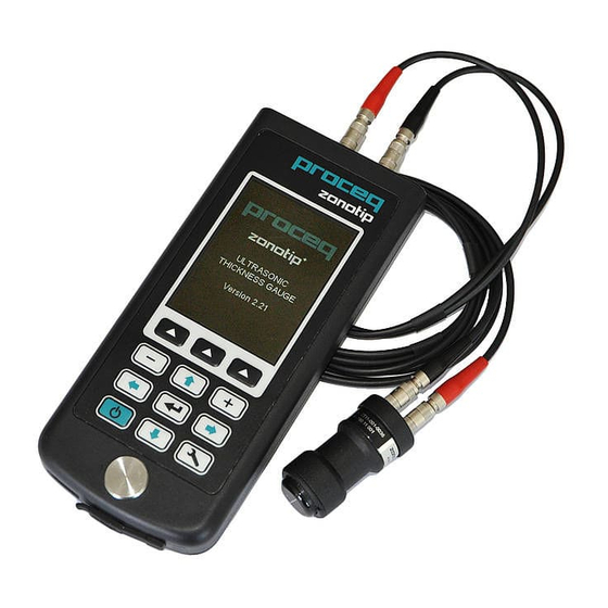
Ports for transducers Functional keys Navigation keys Zeroing sample / test plate USB Port Figure 2: The Zonotip instrument Figure 3: Connection of the 4.0 MHz Figure 4: Connection of the 2.5 MHz trans- transducer. Make sure the red cable is ducer connected to the port with the red dot. -
Page 6: Connect Probes
The optional 2.5 MHz single-element integrated transducer is smaller and requires only one cable (see figure 6). This makes it more convenient to use in smaller areas or in areas that are harder to access. The 2.5 MHz is included when purchasing the Zonotip unit. -
Page 7: First Steps Before Measuring
This process is needed to calibrate the instrument before the first measurement. • Please put a little coupling paste onto the built-in zeroing sample (test plate) of the Zonotip (see figure 2). The thickness of the zeroing sample is 5 mm. -
Page 8: Use Of The Instrument
4.1 The Different Measuring Modes 4.1.1 Overview of Settings / Menu Structures The Zonotip / Zonotip features different measuring modes that can be set in the Setup-Screen: the Norm mode, the Memory mode and the A-Scan mode (Zonotip only). Measuring Mode Memory... - Page 9 4.3.2 Select the number of decimals Discrete 0.01 Sound Vibration English to change the language, please press the functional keys multiple times. German French Italian Language Portuguese Spanish Chinese Russian Measuring units inch Brightness © 2014 Proceq SA...
-
Page 10: Norm Mode
Using the Norm mode is convenient when the measurement results do not have to be recorded. This mode enables the Zonotip to promptly determine the thickness of the test object and to set the “monitor” (5) response range. If “monitor” (5) is set to “inside” and the readings are within the defined limits, the readings are shown in red. -
Page 11: Memory Mode
4.1.3 Memory Mode The Memory mode of the Zonotip / Zonotip allows to promptly determine the thickness of the test object, to record the measurement in the memory of the instrument, to browse them on the display as well as to correct the entries and to conduct re-measurements. -
Page 12: A-Scan Mode
4.1.4 A-Scan Mode (Zonotip only) The A-Scan mode allows excluding measurement inaccuracies, caused by e.g. flaws or cracks in the test object. The signal is visualized on the display as an A-Scan, which allows a more indepth analysis of the reading. -
Page 13: Pictograms
Signal level is maximal Signal level is average Signal level is minimal No signal No measurements Measurement using the ACF method (see chapter 4.2.2) Measurement using the threshold method (see chapter 4.2.2) Overwrite mode (see chapter 4.1.3) © 2014 Proceq SA... -
Page 14: Operation Pictograms A-Scan
4.2.2 Operation Pictograms A-Scan (Zonotip only) Change gate parameters Select signal section to be displayed Selection of the measurement method: the instant the signal within the gate exceeds the threshold (vertical position of the gate) is used for the measurement. -
Page 15: Calibration On Known Material / Determinate The Us Velocity
Set the amplification of the instrument Gain A-Scan 0 - 80 dB inlet path • Fill: reflected in the filled type Type of A-Scan A-Scan Selection of the signal reflection type • Outline: reflected in form of an outline © 2014 Proceq SA... -
Page 16: Velocity Of Longitudinal Ultrasonic Waves
• Connect the thickness gauge to the PC using a USB cable. • Press the button (in color). Please note that the device is in the Memory Mode; otherwise the device will not connect to the PC, enabling you to transfer your data. © 2014 Proceq SA... - Page 17 The software will save the files in the *.csv format, which can then be opened in programs such as Excel or Notepad. Shutdown Press the button If the changes were not saved, the software will warn about that. © 2014 Proceq SA...
-
Page 18: Technical Specifications
45 x ∅23 mm (1.8 x ∅0.9 inch) 24 x ∅16 mm (0.9 x ∅0.6 inch) Size (∅18.5 at the connector) Weight 23 g 16 g Standards and Regulations Applied • ASTM E 797 • EN 15317 © 2014 Proceq SA... -
Page 19: Part Numbers And Accessories
9. Maintenance and Support 9.1 Support Concept Proceq is committed to providing a complete support service for this instrument. It is recom- mended that the user registers the product on the www.proceq.com to obtain valuable information on available updates and other useful information. - Page 20 Five Continent International Mansion, No. 807 Zhao Jia Bang Road Shanghai 200032 Phone +86 21 6317 7479 +86 21 6317 5015 info-china@proceq.com www.proceq.com Subject to change without notice. Copyright © 2014 by Proceq SA, Schwerzenbach Part number: 820 790 01 E Made in Switzerland...
Need help?
Do you have a question about the Zonotip and is the answer not in the manual?
Questions and answers