Table of Contents
Advertisement
Quick Links
Advertisement
Table of Contents

Related Manuals for Epson SRC520


Summary of Contents for Epson SRC520
- Page 1 ROBOT CONTROLLER SRC520 Rev.4 EM015C868F...
- Page 3 ROBOT CONTROLLER SRC520 Rev.4 Copyright 1998, 2000-2001 SEIKO EPSON CORPORATION. All rights reserved.
- Page 4 FOREWORD Thank you for the purchase of our robot for use in precision construction applications. This manual contains information that you need to know how to use the robot controller correctly. Please thoroughly read this and other related manuals before and while using the equipment.
- Page 5 Microsoft Corporation. Other brand and product names are trademarks or registered trademarks of the respective holders. Please direct any inquiries about the use of this manual to: SRC520 SEIKO EPSON CORPORATION Sales Engineering Group TEL: 81-266-24-2004 FAX: 81-266-24-2017...
- Page 6 Safety Precautions Please carefully read this manual and any other manuals before installing this robot system (and definitely before connecting cables). Keep this manual in a handy location for easy access at all times. This sign indicates that a danger of serious injury or WARNING ...
- Page 7 The emergency stop circuit has been changed for double structure for safety. Therefore, the emergency connector standard has been changed. When connecting SRC520 to the emergency stop circuit that used to be connected to SRC500, a converting connector (option) is necessary.
- Page 8 The controller consists of one Control Unit and Drive Unit(s). You may find the controller model name on the front panels of them. The model, SRC520 and SRC520CE, are quite different. Only SRC520CE is in 520CE conformity with the following EC directives:...
-
Page 9: Table Of Contents
TABLE OF CONTENTS Function 1. For Safety Safety Precautions .............. 3 Safety Features ..............5 2. Part Names and Functions System Configuration............7 Standard Specifications ............9 Control Unit ............... 12 2.3.1 Control Unit ............12 2.3.2 Front Panel............12 2.3.3 Rear Panel ............ - Page 10 5.1.3 Checking the Functions ........42 Emergency Stop Switch............ 43 5.2.1 Emergency Stop Switch ........43 5.2.2 Checking the Functions ........43 Pin Assignments ............... 44 Circuit Diagrams ............... 45 5.4.1 Example 1: External emergency stop switch typical application ......45 5.4.2 Example 2: External safety relay typical application........
- Page 11 Pin Assignments ........... 81 9.1.2 Connection Example..........82 Preparation for Communication ........83 10. Jumper Settings for MIB 11. Stand-alone Option for SRC520 11.1 Stand-alone Option ............87 11.2 System Configuration............87 11.3 Installation ................. 87 11.4 Power Supply ..............88 11.5 Extension Emergency Connector Unit......
- Page 12 Pin Assignments for the System Connectors....124 4.2.1 M/C Power ............124 4.2.2 M/C Signal ............125 4.2.3 MOTION.............. 126 Drive Unit ................ 127 4.3.1 System Configuration ......... 127 4.3.2 Module Functions and Layout ......128 4.3.3 Inspecting a Switching Power Supply Module ... 129 Motor Driver Module ............
- Page 13 Function The manual herein explains in detail the functions of the robot controller, SRC520.
- Page 14 Function...
-
Page 15: Function
Function 1. For Safety 1. For Safety 1.1 Safety Precautions This sign indicates that a danger of serious injury or death WARNING will exist if instructions there under are not followed. This sign indicates that ignoring the instructions there under CAUTION may cause harm to people or physical damage to equipment and facilities. - Page 16 [115] side (AC100V to AC120V), the equipment will be damaged seriously. Only install optional hardware specifically designed for the SRC520 in the Control Unit. Do not install any other software than originally installed in the Control Unit at shipping.
-
Page 17: Safety Features
Function 1. For Safety 1.2 Safety Features Provided against unexpected contingencies, the robot features the following safety measures. However, the user is recommended to strictly follow the proper usage of the robot by thoroughly reading the attached manuals at the very beginning. Skipping the proper steps of usage relying on the featured safety functions is highly dangerous. - Page 18 Function 1. For Safety Encoder Cable Disconnection Error Detection: The dynamic brake circuit is activated when the Motor Encoder Signal cable (connecting to the Drive Unit) is disconnected. Motor Overload Detection: The dynamic brake circuit is activated when the load on the motor is detected to exceed its capacity.
-
Page 19: Part Names And Functions
2. Part Names and Functions 2.1 System Configuration The SRC520 is consisted of one Control Unit and Drive Unit(s). One Drive Unit enables controlling up to 4 axes/motors at once. Up to three Drive Units can be connected to one Control Unit. - Page 20 Function 2.1 System Configuration (Part Names and Functions) Example 2 : Three Drive Units and Three Manipulators Manipulator Drive Unit Control Unit Jog Pad Manipulator (option) Drive Unit Manipulator Drive unit...
-
Page 21: Standard Specifications
Function 2.2 Standard Specifications (Part Names and Functions) 2.2 Standard Specifications Item Specification Model SRC520 PC compatible computer optimized for SRC520: : Pentium 200MHz or faster Control Unit HD/RAM : 1GB/32MB or more : Windows 95 Drive Unit Up to four (4) connectable AC Servo Motors Max. - Page 22 For the Control Unit, refer to the “Function 2.3.4 Dimensions”. Size For the Drive Unit, refer to the “Function 2.4.5 Dimensions”. * When only using the Control Unit, the specification is different. Refer to the “Function 11. Stand-alone Option for SRC520”.
- Page 23 Function 2.2 Standard Specifications (Part Names and Functions) SRC520CE is in conformity with the following EC directives: 520CE Conformed to: Applied Standards Machinery directive EN775, EN60204-1 EMC directive EN55011, EN50082-2 Low Voltage directive EN60950...
-
Page 24: Control Unit
As for the power supply when only using the Control Unit, refer to the “11.4 Power Supply” in the “Function 11. Stand-alone Option for SRC520”. Only install optional hardware specifically designed for the SRC520 in the Control Unit. Do not install any other software than originally installed in the Control Unit at shipping. - Page 25 Function 2.3 Control Unit (Part Names and Functions) Open (Certain PC panels may appear differently from the figure.) (10) (11) (1) Signature label: The serial number of the Control Unit is recorded. (2) Connection Check label: The details of the Drive Units(s) and Manipulator(s) to be connected are recorded on the label as shown below: The Manipulator model, Manipulator serial number, DU number (ex: DU1) and Drive Unit serial number.
- Page 26 (10) OPTIONAL DEVICE connector: Connects the optional operating unit. For details, refer to the “Function 4. OPTIONAL DEVICE Connector”. (11) SYSTEM PANEL: Special system panel for SRC520. This has the connectors for operation units and the LED for indicating the status.
-
Page 27: Rear Panel
Function 2.3 Control Unit (Part Names and Functions) 2.3.3 Rear Panel Name and functions as follows: (12) (10) (11) (1) RS-232C connector (COM2): This connector facilitates data communication and centralized control by connecting peripheral equipment and the host computer to the Control Unit. For details, refer to the “Function 9. - Page 28 (AC200V to AC240V) when using the Control Unit with other equipment. When only using the Control Unit, the setting is different. Refer to the “Function 11. Stand-alone Option for SRC520” for the “11.4 Power Supply”. (8) AC OUT: The AC OUT connector outputs the power to the monitor.
-
Page 29: Dimensions
Function 2.3 Control Unit (Part Names and Functions) 2.3.4 Dimensions [mm]... -
Page 30: Control Unit Capability
2.3 Control Unit (Part Names and Functions) 2.3.5 Control Unit Capability The capability of the SRC520 Control Unit with regards to the max. number of controllable manipulators (=motor axes) is as in the table below: When the CP motion is used:... -
Page 31: Drive Unit
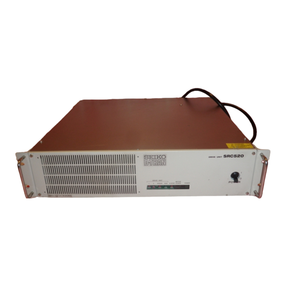
Function 2.4 Drive Unit (Part Names and Functions) 2.4 Drive Unit 2.4.1 Drive Unit The Drive Unit controls the motor/axes as it receives a command from the Control Unit. One Drive Unit is capable of controlling (a motor with) up to four (4) axes. Up to three (3) Drive Units are connectable to a Control Unit. -
Page 32: Rear Panel
Function 2.4 Drive Unit (Part Names and Functions) 2.4.3 Rear Panel M/C POWER AC OUTLET AC 200-240V INPUT AC 200-240V EMERGENCY D I/O MOTION M/C SIGNAL (1) AC OUTLET: Socket for the AC200V (or the local equivalent) power supply to the Control Unit. The PC power cable included in the accessories should be connected to this AC OUTLET. -
Page 33: Drive Unit - Interior Layout
Function 2.4 Drive Unit (Part Names and Functions) 2.4.4 Drive Unit – Interior Layout Do not open the cover(s) of the Control and Drive Units except while maintaining them. Because of the high voltage charger inside the Control WARNING and Drive Units, there is a risk of fatal electrical shock even when its main power is OFF. - Page 34 Function 2.4 Drive Unit (Part Names and Functions) (3) Motor Driver module: The Motor Driver module receives a reference from DMB, and, outputs the three-phase current to supply power to the motor. (The figure in the previous page shows a sample of Drive Unit for a 4-axes robot. From left to right: Axis 1 through (4) Switching Power Supply: The Supplied AC200V (or the local equivalent) power is regulated here and, is output as DC24V.
-
Page 35: Dimensions
Function 2.4 Drive Unit (Part Names and Functions) 2.4.5 Dimensions [mm]... - Page 36 Function 2.4 Drive Unit (Part Names and Functions)
-
Page 37: Installation
Note SRC5**/SPEL 95 Introduction Manual 1 book SRC5**/SPEL 95 User’s Guide 1 book SRC5**/SPEL 95 Appendix 1 book Robot Controller SRC520 manual 1 book Manipulator manual 1 book/model Pulse Generating Board Depends on Remote I/O Board Robot controller option manual... -
Page 38: Environmental Requirements
Function 3.2 Environmental Requirements (Installation) 3.2 Environmental Requirements In order to safety optimize the controller’s performance; the controller must be placed in an environment which satisfies the following conditions. Item Condition Ambient temperature 5 to 40°C (with minimal variation) Ambient relative 20 to 80 % (with no condensation) humidity... -
Page 39: Power Supply
The socket-outlet shall be installed near the equipment and shall be easily accessible. NOTE The power supply specification is different from the one shown above when only using the Control Unit. Refer to the “11.4 Power Supply” in the “Function 11. Stand-alone Option for SRC520”. -
Page 40: Power Plug
Function 3.3 Power Supply (Installation) 3.3.2 Power Plug The AC power cable of the Drive Unit is equipped with a power plug. Make sure that the plug is compatible with the power outlet in your area. If not, replace the attached plug with the one that is suitable in your area. -
Page 41: Cable Connection
Function 3.4 Cable Connection (Installation) 3.4 Cable Connection Make sure that the power to the Control Unit and the Drive Unit is turned OFF before connecting or disconnecting any cables. Failure to do so may WARNING cause electric shock and may damage the units. Check on the Connection Check Label and DU number (at Control Unit) and Signature Labels (at Drive Unit &... -
Page 42: Typical Cable Connection (Single Manipulator)
Function 3.4 Cable Connection (Installation) 3.4.1 Typical Cable Connection (Single Manipulator) The robot must be connected as follows in order to be activated properly. The diagram indicates a standard cable connection for a single Manipulator configuration. Drive Unit (1) M/C Power Cable M/C POWER Manipulator (2) M/C Signal Cable... - Page 43 CAUTION [115] side (AC100V to AC120V), the equipment will be damaged seriously. As for the power supply when only using the Control Unit, refer to the “11.4 Power Supply” in the “Function 11. Stand-alone Option for SRC520”.
- Page 44 Function 3.4 Cable Connection (Installation) (7) AC Power cable: Cables for AC200V (or the local equivalent) power supply to the Drive Unit. The AC power cable and the AC OUTLET connector on the Drive Unit are directly connected inside the unit. Therefore, no matter if the Drive Unit’s switch CAUTION is ON or OFF, the AC OUTLET connector is constantly outputting AC200V (or the local equivalent) power which requires extra caution.
-
Page 45: Connecting Drive Unit And Control Unit
Function 3.4 Cable Connection (Installation) 3.4.2 Connecting Drive Unit and Control Unit The setup data for the Drive Unit is stored in the Control Unit. When connecting those units, it is crucial that the Drive Unit must be itself specified on the Connection Check Label on the front panel of the Control Unit be connected. - Page 46 Drive Unit’s No. is indicated on the label as shown below. DU number label(s) at the back of Control Unit: Drive Unit serial number - Identifying proper unit: Drive Unit’s serial No. is indicated on the label as shown below. :SRC520 MODEL DRIVE UNIT :00006 SERIAL NO.
-
Page 47: Connecting A Drive Unit To The Manipulator
Function 3.4 Cable Connection (Installation) 3.4.3 Connecting a Drive Unit to the Manipulator Connect a Drive Unit to the Manipulator by using M/C Power cable and M/C Signal cable. M/C power cable : M/C Power cable has round connectors with 17-pins on both ends. Connect the female connector to the POWER connector at the Manipulator and the male connector to the M/C POWER connector at the Drive Unit. -
Page 48: Noise Countermeasures
Function 3.5 Noise Countermeasures (Installation) 3.5 Noise Countermeasures The followings must be observed in the system’s cable wiring: ・ The earth wire of the power supply should be grounded. (Ground resistance: less than 100Ω) It is important to ground the frame of Drive Unit not only for prevention from electric shock, but also for reducing the influence of electric noise around the Drive Unit. - Page 49 Function 3.5 Noise Countermeasures (Installation) ・ Make sure that the induction elements used to connect to the controller’s I/O (such as relays and solenoid valves) have surge suppressors. If an induction element without surge suppressor has be used, make sure to connect a rectifying diode right in front of the induction element.
- Page 50 Function 3.5 Noise Countermeasures (Installation)
-
Page 51: Optional Device Connector
Function 4. OPTIONAL DEVICE connector 4. OPTIONAL DEVICE Connector 4.1 OPTIONAL DEVICE Connector This is the connector for JP500 (Jog Pad) or OP500 (Operation Pendant) as an optional operation unit. The “Port Short Connector,” an accessory that comes with the Control Unit, must be connected to this connector if an operation unit is not used. -
Page 52: Pin Assignments
Function 4. OPTIONAL DEVICE connector 4.4 Pin Assignments In case you wish to connect your own mode-switching switch to the OPTIONAL DEVICE Port Short connector, refer to the following pin assignments. Pin number Signal name Pin number Signal name ENABLE KEY1 E_SW11 KEY2... -
Page 53: Emergency Connector
Function 5.1 Safety Door Switch and Latch Release Switch (EMERGENCY connector) 5. EMERGENCY Connector NOTE For safety, refer to the SRC5**/SPEL 95 Introduction manual for “1. Safety”. When the system is “Multi-Manipulator” to control two or more manipulators with one NOTE Control Unit, refer to the Multi-Manipulator manual for the “1.3 Safety”... -
Page 54: Latch Release Switch
Function 5.1 Safety Door Switch and Latch Release Switch (EMERGENCY connector) 5.1.2 Latch Release Switch Software latches the following conditions: - The safety door is open. - The operation mode is “ATTEND”. The EMERGEMCY connector has an input terminal for a latch release switch that cancels the latched conditions. -
Page 55: Emergency Stop Switch
Function 5.2 Emergency Stop Switch (EMERGENCY connector) 5.2 Emergency Stop Switch Do refer to the typical application diagram in the “Function 5.4 Circuit Diagrams” when wiring to the EMERGENCY connector so that it should not WARNING dysfunction the emergency stop input at the Control Unit via the OPTIONAL DEVICE connector. -
Page 56: Pin Assignments
Function 5.3 Pin Assignments (EMERGENCY connector) 5.3 Pin Assignments The EMERGENCY connector pin assignments are as follows: Pin No. Signal Function E_SW11 Emergency Stop switch output (1) E_SW12 E.STOP1+ Emergency Stop input 1 (+) E.STOP1- Emergency Stop input 1 (-) E.STOP OUT Emergency Stop condition output (Relay contact) -
Page 57: Circuit Diagrams
Function 5.4 Circuit Diagrams (EMERGENCY connector) 5.4 Circuit Diagrams 5.4.1 Example 1: External emergency stop switch typical application... -
Page 58: Example 2: External Safety Relay Typical
Function 5.4 Circuit Diagrams (EMERGENCY connector) 5.4.2 Example 2: External safety relay typical application... -
Page 59: D-I/O Connector
Function 6. D-I/O Connector 6. D-I/O Connector The D-I/O connector is for connecting your input/output equipment to the system. A standard controller model has one D-I/O port at the rear panel. It has 16 pins each for input and output respectively. The following table shows the applicable Drive Unit for the input/output bit numbers. -
Page 60: Input Circuit
Function 6.1 Input Circuit (D-I/O Connector) 6.1 Input Circuit : DC12 to 24V ±10% Input Voltage Range On Voltage : DC10.8V (min.) Off Voltage : DC5V (max.) Input Current : 10mA (TYP) at DC24V input The input bit numbers in the following diagrams presume the standard Drive Unit (DU1). Typical Input Circuit Application 1 : NPN type (the standard for the regions outside Europe) GND +DC 1 Input No.0 to 3 common... - Page 61 Function 6.1 Input Circuit (D-I/O Connector) Typical Input Circuit Application 2 : PNP type (the European standard) GND +DC 1 Input No.0 to 3 common 470 Ω 2.2 kΩ 2 Input No.0 3 Input No.1 (ditto) 4 Input No.2 (ditto) 5 Input No.3 (ditto) 26 Input No.4 to 7 common...
-
Page 62: Output Circuit
Function 6.2 Output Circuit (D-I/O Connector) 6.2 Output Circuit : DC12V to 24V ±10% Rated Output Voltage Maximum Output Current : TYP 100mA/1 output Output Driver : Photo coupler Saturation Voltage : 1.6V or under The input bit numbers in the following diagrams presume the standard Drive Unit (DU1). Typical Output Circuit Application 1 : NPN type (the standard for the regions outside Europe) Be careful not to misconnect the output circuit because it has no protection CAUTION... - Page 63 Function 6.2 Output Circuit (D-I/O Connector) PNP type (the European standard) Typical Output Circuit Application 2 : Be careful not to misconnect the output circuit because it has no protection CAUTION circuit which protects the circuit from short-circuit and reverse-connection. GND +DC No.0 to 3 common Output...
-
Page 64: Pin Assignments
Function 6.3 Pin Assignments (D-I/O Connector) 6.3 Pin Assignments The internal power supply does not output to the D-I/O connector. Make sure that the power is supplied by an external power source. 6.3.1 D-I/O connector – Pin Assignments The input/output bit numbers shown below presume a standard Drive Unit (DU1). Pin No. -
Page 65: Optional Cable - Pin Assignments
Function 6.3 Pin Assignments (D-I/O Connector) 6.3.2 D-I/O connector optional cable – Pin Assignments The D-I/O connector cable is an optional part. Pin No. Signal Name Pin No. Signal Name Input common 0 to 3 Output common 0 to 3 Input No.0 Output No.0 Input No.1... - Page 66 Function 6.3 Pin Assignments (D-I/O Connector)
-
Page 67: Extension I/O Board - Optional
Function 7.1 Extension I/O Board (Extension I/O Board – Optional) 7. Extension I/O Board - Optional 7.1 Extension I/O Board Mount the extension I/O board on the ISA slot in the Control Unit when extra I/Os are desired. One additional I/O board extends by 32 pins each for input and output. The I/Os can be extended up to 464 each for input and output respectively (including those for Remote I/O). -
Page 68: Protected Extension I/O Board
Function 7.2 Protected Extension I/O Board (Extension I/O Board – Optional) 7.2 Protected Extension I/O Board 7.2.1 Protected Extension I/O Board : Jumper Settings The I/O board address is defined by the jumpers JP1, 2, and 3. When assigning the I/O boards to 0700H to 0707H, set them as follows: JP1 : Short-circuit 16-15, 14-13, 12-11, 10-9 and 8-7. -
Page 69: Input Circuit
Function 7.2 Protected Extension I/O Board (Extension I/O Board – Optional) 7.2.2 Protected Extension I/O Board : Input Circuit The following diagrams illustrate cases where #48 through #79 are assigned to the Extension I/O’s inputs and outputs. The I/O number assignment depends on the SPEL 95 settings. - Page 70 Function 7.2 Protected Extension I/O Board (Extension I/O Board – Optional) Protected Extension I/O Board Typical Input Circuit Application 2 : PNP type (the European standard): GND +DC 1 Input No.48 to 51 common 470 Ω 2.2 kΩ 3 Input No.48 4 Input No.49 (ditto) 5 Input No.50...
-
Page 71: Output Circuit
Function 7.2 Protected Extension I/O Board (Extension I/O Board – Optional) 7.2.3 Protected Extension I/O Board : Output Circuit The following diagrams illustrate cases where #48 through #79 are assigned to the Extension I/O’s inputs and outputs. The I/O number assignment depends on the SPEL 95 settings. - Page 72 Function 7.2 Protected Extension I/O Board (Extension I/O Board – Optional) Protected Extension I/O Board Typical Output Circuit Application 2 : PNP type (the European standard) GND +DC No. 48 Output No. 49 Output (ditto) No. 50 Output (ditto) No. 51 Output (ditto) Output No.48 to 51 common...
-
Page 73: Extension I/O Board
Function 7.3 Extension I/O Board (Extension I/O Board – Optional) 7.3 Extension I/O Board (the standard for the regions outside Europe) 7.3.1 Extension I/O Board : Jumper Settings The I/O board address is defined by the jumpers JP1, 2, and 3. When assigning the I/O boards to 0700H to 0707H, set them as follows: JP1 : Short-circuit 16-15, 14-13, 12-11, 10-9 and 8-7. -
Page 74: Input Circuit
Function 7.3 Extension I/O Board (Extension I/O Board – Optional) 7.3.2 Extension I/O Board : Input Circuit The input circuit is the same as the NPN type of the protected extension I/O board. Refer to the “Function 7.2.2 Protected Extension I/O board : Input Circuit” for details. 7.3.3 Extension I/O Board : Output Circuit The following diagrams illustrate cases where #48 through #55 are assigned to the Extension I/O’s inputs and outputs. - Page 75 Function 7.3 Extension I/O Board (Extension I/O Board – Optional) Extension I/O Board Typical Output Circuit Application 2 : Output #56 to #79 Be careful not to misconnect the output circuit because it has no protection CAUTION circuit which protects the circuit from short-circuit and reverse-connection. GND +DC Output No.
-
Page 76: Extension I/O Board : Pin Assignments
Function 7.4 Extension I/O Board : Pin Assignments (Extension I/O Board – Optional) 7.4 Extension I/O Board : Pin Assignments 7.4.1 Extension I/O Board : Pin Assignments (NPN type) NPN:Pin No. 1-50 Pin No. Signal Name Pin No. Signal Name Input common A (48 to 51) Output common A (GND: 48 to 51) Output No.48... - Page 77 Function 7.4 Extension I/O Board : Pin Assignments (Extension I/O Board – Optional) NPN:Pin No. 51-100 Pin No. Signal Name Pin No. Signal Name Input common B (52 to 55) Output common B (GND: 52 to 55) Output No.52 Input No.52 Output No.53 Input No.53 Output No.54...
-
Page 78: Pin Assignments (Pnp Type)
Function 7.4 Extension I/O Board : Pin Assignments (Extension I/O Board – Optional) 7.4.2 Extension I/O Board : Pin Assignments (PNP type) PNP:Pin No. 1-50 Pin No. Signal Name Pin No. Signal Name Input common A (48 to 51) Output common A (+DC: 48 to 51) Output No.48 Input No.48 Output No.49... - Page 79 Function 7.4 Extension I/O Board : Pin Assignments (Extension I/O Board – Optional) PNP Pin No. 51-100 Pin No. Signal Name Pin No. Signal Name Input common B (52 to 55) Output common B (+DC: 52 to 55) Output No.52 Input No.52 Output No.53 Input No.53...
-
Page 80: Extension I/O Connector
Function 7.5 Extension I/O Connector (Extension I/O Board – Optional) 7.5 Extension I/O Connector 7.5.1 Pin Layout of Extension I/O Connector An internal power is not supplied to the Extension I/O connector. Therefore, an external power source must be supplied. 7.5.2 Extension I/O Connector Cable The Extension I/O connector cable is an optional part. -
Page 81: Cable - Pin Assignment
Function 7.5 Extension I/O Connector (Extension I/O Board – Optional) 7.5.3 Extension I/O Connector Cable – Pin Assignment Extension I/O connector cable - Pin Assignment : NPN type Pin No. Signal Name Pin No. Signal Name Input common A (48 to 51) Output common A (+DC: 48 to 51) Output common A (GND: 48 to 51) Input No.48... - Page 82 Function 7.5 Extension I/O Connector (Extension I/O Board – Optional) Pin No. Signal Name Pin No. Signal Name Input common E (64 to 67) Output common E (+DC: 64 to 67) Output common E (GND: 64 to 67) Input No.64 Output No.64 Input No.65 Output No.65...
- Page 83 Function 7.5 Extension I/O Connector (Extension I/O Board – Optional) Extension I/O connector cable – Pin Assignment : PNP type Pin No. Signal Name Pin No. Signal Name Input common A (48 to 51) Output common A (GND: 48 to 51) Output common A (+DC: 48 to 51) Input No.48 Output No.48...
- Page 84 Function 7.5 Extension I/O Connector (Extension I/O Board – Optional) Pin No. Signal Name Pin No. Signal Name Input common E (64 to 67) Output common E (GND: 64 to 67) Output common E (+DC: 64 to 67) Input No.64 Output No.64 Input No.65 Output No.65...
-
Page 85: I/O Remote Settings
Function 8. I/O Remote Settings 8. I/O Remote Settings This section describes functions and timing of input/output signals. The remote functions may be assigned to your standard or extension I/O board(s) to enhance robot control - either from an operational unit of your choice or a sequencer. The user defines the I/O number that a remote function is assigned to. -
Page 86: I/O Signal Description
Function 8.1 I/O Signal Description (I/O Remote Settings) 8.1 I/O Signal Description A standard I/O input and output is 16 points each. Extension I/O board(s) is necessary for input/output of all the functions. 8.1.1 Input Signal Remote input is a function in which operation of the manipulators or Controller is enabled by input of a signal when the fixed conditions for each function are fulfilled. - Page 87 Function 8.1 I/O Signal Description (I/O Remote Settings) *3) Specify the manipulator number with Mnp.No.0-3/4 bit referring to the table below. Specified Mnp. No.0 Mnp. No.1 Mnp. No. 2 Mnp. No.3 Manipulator 0 : OFF, 1 : ON (*4) Specify the group number with Grp. No.0-3/4 bit referring to the table below. Specified Grp No.0 Grp No.1...
-
Page 88: Output Signal
Function 8.1 I/O Signal Description (I/O Remote Settings) 8.1.2 Output Signal Remote output is a function to output the status of the manipulators, the status of the Controller and operating mode and so on, externally to the Controller. The items that can be set are as follows: Function Description Outputs the motor mode status (Motor mode ON:ON). - Page 89 Function 8.1 I/O Signal Description (I/O Remote Settings) Function Description Outputs the working mode status. ON in the AUTO mode (OFF AUTO mode in the PROGRAMMING mode). Outputs the operation mode status. ON in the ATTEND ATTEND mode operation mode (OFF in the NORMAL operation mode). Outputs the READY status of the Controller (ON in the READY READY and RESET status).
-
Page 90: Timing Specifications
8.2 Timing Specifications 8.2.1 Design Notes for Input Signal The following charts indicate timing sequence of the primary operations of the SRC520. The indicated lapse (time duration) should be referred to only as reference value since the actual timing value varies depending on the number of manipulators and running tasks as well as CPU speed of the control unit PC. -
Page 91: Diagram For Program Execution Sequence
Function 8.2 Timing Specifications (I/O Remote Settings) 8.2.3 Timing Diagram for Program Execution Sequence 200msec. 100msec. START monitor Output 20msec. In PAUSE Output 500msec. RESET Output 10msec. Grp. No. Output START Input PAUSE Input RESET Input Grp. No. Input Select the number. *1: The duration varies depending on the Quick Pause (QP) setting and the program’s operating status at the time of Pause input. -
Page 92: Diagram For Emergency Stop Sequence
Function 8.2 Timing Specifications (I/O Remote Settings) 8.2.5 Timing Diagram for Emergency Stop Sequence Power status Output 10msec. START monitor Output 500msec. RESET Output 20msec. Emergency Stop Output RESET Input Emergency Stop Input *1: It is the timing of READY output/input when using the background task. 8.2.6 Timing Diagram for Error Generating Sequence START monitor... -
Page 93: Rs-232C Settings
The Standard Control Unit comes with two RS-232C channels to facilitate controlling of the data communication among the host computer, robots and their peripheral equipment. 9.1 RS-232C cable The RS-232C cable is not included in the standard SRC520 model. Prepare them as necessary. -
Page 94: Connection Example
Function 9.1 RS-232C cable (RS-232C Settings) 9.1.2 Connection Example Example 1: Standard [Control Unit] [Peripheral equipment] Signal Name Pin No. Pin No. Signal Name Clamp Hood Example 2: H/W Flow Control [Control Unit] [Peripheral equipment] Signal Name Pin No. Pin No. Signal Name Clamp Hood... -
Page 95: Preparation For Communication
Function 9.2 Preparation for Communication (RS-232C Settings) 9.2 Preparation for Communication For communication via RS-232C between the Control Unit and peripheral equipment to work, the port configuration on both units must be the same. Make sure that the settings on the following parameters on both units match. You may use either SETCOM command or go to [Setting of a Robot Controller] - [COM Port] to set up the following parameters:... - Page 96 Function 9.2 Preparation for Communication (RS-232C Settings)
-
Page 97: Jumper Settings For Mib
Function 10. Jumper Setting for MIB Jumper Settings for MIB (Motion Interface Board) The Motion Interface Board (MIB) is installed in the Control Unit and, it enables communication between the Control Unit and Drive Unit. The number of MIBs that can be installed in one Control Unit is up to three (3) at maximum. - Page 98 Master (XF signal) ○ Slave ○ : Short JP9, JP10 Setup the type of Drive Unit connected with the MIB. Setting ○ Drive Unit for SRC520 Drive Unit for SRC500 ○ : Short JP11 The normal settings are open.
-
Page 99: Stand-Alone Option For Src520
Function 11. Stand-alone Option for SRC520 11. Stand-alone Option for SRC520 This section describes a Stand-alone Option that allows you to use the SRC520’s Control Unit only. 11.1 Stand-alone Option A Stand-alone Option allows forming the Control Unit own system including the Emergency Stop input and Safety Door input by connecting an Extension Emergency Connector Unit to the Control Unit. -
Page 100: Power Supply
Function 11. Stand-alone Option for SRC520 11.4 Power Supply PC power cable for power source supply from the Drive Unit can not be used when using the Control Unit only. Use the proper PC power cable conforming to the specification of the connecting power source. -
Page 101: Components
Function 11. Stand-alone Option for SRC520 11.5.2 Components of Extension Emergency Connector Unit The Extension Emergency Connector Unit consists of the following parts. Extension Emergency Connector Board : Provides the extension emergency connector function of the Drive Unit for the Control Unit. -
Page 102: Pin Assignments
Function 11. Stand-alone Option for SRC520 11.5.4 Pin Assignments Pin assignments of the Extension Emergency Connector are as follows: Pin No. Signal Name Function E_SW11 Emergency Stop switch output (1) E_SW12 E.STOP1+ Emergency Stop input 1 (+) E.STOP1- Emergency Stop input 1 (-) E.STOP OUT... -
Page 103: Circuit Diagram
Function 11. Stand-alone Option for SRC520 11.5.5 Circuit Diagram Example 1: External emergency stop switch typical application Emergency Stop switches of an operating unit Emergency Stop detection Emergency Stop detection Emergency Stop condition control External +24V Safety Door input 1... - Page 104 Function 11. Stand-alone Option for SRC520 Example 2: External safety relay typical application Emergency Connector Board External+24V Emergency Stop switches of an operating Fuse* unit External +24VGND External +24V External safety relay (The above diagram is simplified for Emergency representation.)
-
Page 105: Mib
For jumper functions, refer to the “Function 10. Jumper Settings for MIB (Motion Interface Board)”. 11.7 Option The options for SRC520, such as the Operation Units (JP500 and OP500), Extension I/O Board and Pulse Generating Board, are available to use even in the Control Unit system only. - Page 106 Function 11. Stand-alone Option for SRC520...
-
Page 107: Maintenance
Maintenance The manual herein explains the maintenance procedure for each unit in the robot controller, SRC 520. - Page 108 Maintenance...
-
Page 109: Safety Precautions On Maintenance
Maintenance 1. Safety Precautions on Maintenance 1. Safety Precautions on Maintenance This sign indicates that a danger of serious injury or WARNING death will exist if the instructions thereunder are not followed. This sign indicates that ignoring the instructions CAUTION thereunder may cause serious harm to people or physical damage to equipment and facilities. - Page 110 Maintenance 1. Safety Precautions on Maintenance CAUTION It is possible that the Motor Driver modules both in the Drive Unit and the Switching Power Supply can become very hot. If you maintain these units, examine the surface temperature, and wear protective gloves if necessary. Do not remove any parts that are not covered in this manual.
-
Page 111: Hardware Configuration
Maintenance 2. Hardware Configuration 2. Hardware Configuration 2.1 Control Unit, Drive Unit and Manipulator The figure below illustrates the hardware (Control Unit, Drive Units and Manipulators) interrelation. In exchanging a module in any of the units, refer to an appropriate section in this manual to follow the instructions and the setting recommendations. -
Page 112: Optional Boards
Maintenance 2. Hardware Configuration 2.2 Optional Boards Control Unit Computer Optional Boards Remote I/O Board Pulse Generating Extension I/O Board Board* (Set the jumper for (Set the jumper for (Set the jumper for I/O address and I/O address) I/O address) the number of I/O) .. -
Page 113: Control Unit
Maintenance 3.1 Overview (Control Unit) 3. Control Unit 3.1 Overview The Control Unit internal layout: CPU board Switching Power Supply CD-ROM Drive FDD : upper HDD : lower Drive Bay Unit Filter System Panel... -
Page 114: Replacing The Mib
Maintenance 3.2 Replacing the MIB (Control Unit) 3.2 Replacing the MIB When MIB is suspected to be defective, replace the board by following the steps below: (1) Shut down Windows 95. Turn OFF the Control and Drive Units. (2) Disconnect the Motion Interface cable. (3) Remove the four screws on both sides of the Control Unit. - Page 115 Maintenance 3.2 Replacing the MIB (Control Unit) (5) Remove two affixing screws, and then take the metal fitting off from the board. Metal Fitting (6) Remove the affixing screw from MIB and remove the MIB out of the slot in the Control Unit.
- Page 116 Maintenance 3.2 Replacing the MIB (Control Unit) (8) Set the jumpers on the new MIB exactly the same as on the old board. Refer to the “Function 10. Jumper Settings for MIB (Motion Interface Board)” for details of the jumper functions. (9) Connect the cable from the System panel to the new MIB.
- Page 117 Maintenance 3.2 Replacing the MIB (Control Unit) (11) Loosen the screws that are holding the angles on the metal fitting. The angle comes in three different sizes to accommodate different board sizes. Select the one that fits. (12) Affix the metal fitting to the Control Unit. (13) Adjust the angle and fix it inside the unit using screws.
-
Page 118: Replacing The Extension Emergency Connector Unit
Maintenance 3.3 Replacing the Extension Emergency Connector Unit (Control Unit) 3.3 Replacing the Extension Emergency Connector Unit When replacing the Extension Emergency Connector Unit that allows you to use the Control Unit only, follow the steps below: (1) Shut down Windows 95. Turn OFF the Control and Drive Units. (2) Disconnect the Motion Interface cable. - Page 119 Maintenance 3.3 Replacing the Extension Emergency Connector Unit (Control Unit)) (5) Remove two affixing screws, and then take the metal fitting off from the board. (6) Disconnect the cable connecting between the MIB and Extension Emergency Connector Board. (7) Unfasten an affixing screw from the Extension Emergency Connector Board and remove the Board.
- Page 120 Maintenance 3.3 Replacing the Extension Emergency Connector Unit (Control Unit) (13) Place the Control Unit Cover back on and secure it with the screws. (14) Connect the Motion Interface cable.
-
Page 121: Replacing An Optional Board
Maintenance 3.4 Replacing an Optional Board (Control Unit) 3.4 Replacing an Optional Board When replacing an optional board(s), refer to the “Maintenance 3.2 Replacing the MIB” and follow the procedure. If there is any jumper set on the old board, it must be set on the new board exactly the same as on the old board. -
Page 122: Replacing The System Panel
Maintenance 3.5 Replacing the System Panel (Control Unit) 3.5 Replacing the System Panel If the System Panel is suspected to be defective, replace the System Panel by following the steps described in the section, “3.5.1” and 3.5.2”, as follows: 3.5.1 Removable HD Unit Model Removal (1) Shut down Windows 95, and then turn OFF the power on both the Control and Drive Units. - Page 123 Maintenance 3.5 Replacing the System Panel (Control Unit) (6) Remove an affixing screw from MIB and remove the MIB out of the slot in the Control Unit. (7) Disconnect the cable from MIB by releasing the connector lock as shown below. (8) Disconnect any cables that are connected to the Drive Bay Unit (DC-ROM drive, FDD and HDD mounting case).
- Page 124 Maintenance 3.5 Replacing the System Panel (Control Unit) (10) Unscrew the mounting screws on the System Panel and remove it from the Drive Bay Unit. (11) Remove the two screws on the HDD mounting case and remove it from the System Panel.
- Page 125 Maintenance 3.5 Replacing the System Panel (Control Unit) Installation (1) Attach the HDD mounting case to a new system panel with the four screws. Match the faces of the case and the system panel to flatten. Screw Screw Face of the system panel Face of the HDD mounting case (2) Install the System Panel in the Drive Bay Unit and secure it with the screws.
- Page 126 Maintenance 3.5 Replacing the System Panel (Control Unit) (3) Install the Drive Bay Unit and fix it with the screws. (4) Connect the cables for the Drive Bay Unit (HDD mounting case, CD-ROM drive and FDD) back. (5) Connect the cable from the System Panel to the MIB. (6) Attach the MIB on the option slot in the Control Unit and fix it with the screw.
- Page 127 Maintenance 3.5 Replacing the System Panel (Control Unit) (7) Loosen the screws that are holding the angles on the metal fitting. (8) Affix the metal fitting to the Control Unit. (9) Adjust the angle and fix it inside the unit using screws. The angle must be adjusted to hold down the board not too tightly.
-
Page 128: Built-In Hdd Model
Maintenance 3.5 Replacing the System Panel (Control Unit) 3.5.2 Built-in HDD Model Removal (1) Shut down Windows 95, and then turn OFF the power on both the Control and Drive Units. Disconnect the Operation Unit or Port Short connector from the OPTIONAL DEVICE connector. - Page 129 Maintenance 3.5 Replacing the System Panel (Control Unit) Disconnect any cables that are connected to the Drive Bay Unit (HDD, CD-ROM drive and FDD). Unscrew all the mounting screws on the Drive Bay Unit to remove the unit. (6) Unscrew the mounting screws on the HDD and remove the HDD from the Drive Bay Unit.
- Page 130 Maintenance 3.5 Replacing the System Panel (Control Unit) Unscrew the mounting screws on the System Panel and remove it from the Drive Bay Unit. Remove the flat cable connecting to the MIB.
- Page 131 Maintenance 3.5 Replacing the System Panel (Control Unit) Installation Connect the flat cable of the new System to the MIB. Install the System Panel in the Drive Bay Unit and secure it with the screws. Affix the four mounting screws on the HDD temporarily. Match the screws on the upper two through holes and fasten to secure the HDD position.
- Page 132 Maintenance 3.5 Replacing the System Panel (Control Unit) (4) Install the Drive Bay Unit and fix it with the screws. (5) Connect the cables for the Drive Bay Unit (HDD, CD-ROM drive and FDD) back. (6) Place the Upper Cover of the Control Unit back on and fix it with the screws. Connect the Motion Interface cable, PC Power cable and Monitor cable.
-
Page 133: Cleaning And Replacing The Fan Filter
Maintenance 3.6 Cleaning and Replacing the Fan Filter (Control Unit) 3.6 Cleaning and Replacing the Fan Filter When you clean and replace the Fan Filter, follow the procedure below: (1) Close down Windows 95. Then, turn OFF the power on both the Control and Drive Units. -
Page 134: Replacing The Hdd For Removable Hd Unit Model
Maintenance 3.7 Replacing the HDD for Removable HD Unit Model (Control Unit) 3.7 Replacing the HDD for Removable HD Unit Model Do not shock, shake or drop the HDD, FDD and CD-ROM drive. CAUTION When these disk drives are shocked physically, it may damage the contained data. For the previous model with a built-in HDD, refer to the “3.5.2 Built-in HDD Model”... -
Page 135: Drive Unit
Maintenance 4.1 Overview (Drive Unit) 4. Drive Unit 4.1 Overview M/C Power Connector M/C Signal Connector Rear Panel Motion Connector Motor Driver Modules Switching Power Regeneration Supply Module Module Axis Axis Axis Axis Main Power Supply Circuit Drive Main Module Board (DMB) Drive Power Board (DPB) -
Page 136: Pin Assignments For The System Connectors
Maintenance 4.2 Pin Assignments for the System Connectors (Drive Unit) 4.2 Pin Assignments for the System Connectors The following tables show the pin assignments for the M/C power connector, M/C signal connector and Motion connector respectively. As for the pin assignments of the connectors not covered in this section, refer to the function volume in this manual. -
Page 137: M/C Signal
Maintenance 4.2 Pin Assignments for the System Connectors (Drive Unit) 4.2.2 M/C Signal Pin No. Signal Pin No. Signal Pin No. Signal 1HOME ENC+5V ENC+5V 4HOME ENC+5V EMB1 +24V HCOM ENC+5V 3HOME ENC+5V ENC+5V EMB2 +24V 2HOME ENC+5V ENC+5V NOTE The Drive Unit and Manipulator’s pin numbering layout differs: one is lined horizontally and the other is lined vertically. -
Page 138: Motion
Maintenance 4.2 Pin Assignments for the System Connectors (Drive Unit) 4.2.3 MOTION Pin No. Signal Pin No. Signal Pin No. Signal ED4+ (NC) ED4- RAS+ RESMIB+ ED2+ RAS- RESMIB- ED2- EA13+ E_STOP001 ED0+ EA13- E_STOP002 ED0- EA11+ E_SW21 RDEN+ EA11- (NC) RDEN- EA9+... -
Page 139: Drive Unit
Maintenance 4.3 Drive Unit (Drive Unit) 4.3 Drive Unit 4.3.1 System Configuration... -
Page 140: Module Functions And Layout
Maintenance 4.3 Drive Unit (Drive Unit) 4.3.2 Module Functions and Layout The Drive Unit consists of Main Power Supply Circuit module, Motor Power module and Switching Power Supply module. The functions of each module are described in the table below. The following figure illustrates the positions in the Drive Unit for each module to be installed. -
Page 141: Inspecting A Switching Power Supply Module
Maintenance 4.3 Drive Unit (Drive Unit) 4.3.3 Inspecting a Switching Power Supply Module The Switching Power Supply module rectifies AC200V (or the local equivalent) and outputs DC24V. The DC24V is converted by the DPB to supply power to: VCC (+5V), the motor driver (+5V) and the encoder (5V). -
Page 142: Motor Driver Module
Maintenance 4.4 Motor Driver Module (Drive Unit) 4.4 Motor Driver Module 4.4.1 Layout and Functions Layout Signature Label CT data Fuse Signature Label The Signature Label on the radiator (heat slinger) indicates capacity in wattage for each Motor Driver module. Model Capacity (W) CACR-A5-SU3C... -
Page 143: Replacing A Motor Driver Module
Maintenance 4.4 Motor Driver Module (Drive Unit) 4.4.2 Replacing a Motor Driver Module Replace a Motor Driver module by following the steps described below. Make sure that the wattage of the new Motor Driver module is correct. When the CAUTION inappropriate wattage module is connected with the Drive Unit, the robot may not function properly or may be damaged. - Page 144 Maintenance 4.4 Motor Driver Module (Drive Unit) Lift up the Motor Driver module so that the cable connected on the back can be disconnected. Compress projections on both sides of the connector to disconnect the cable smoothly. 2) Pull out 1) Compress (7) Connect the cable to a new Motor Driver module.
-
Page 145: Setting Up The New Ct Data On The Spel 95
Maintenance 4.4 Motor Driver Module (Drive Unit) “ 4.4.3 Setting Up the New CT Data on the SPEL 95 After a Motor Driver module is replaced, set up the CT data in the Control Unit by following the steps below. For details of CT data, refer to the “CT data”... -
Page 146: Dpb (Drive Power Board)
Maintenance 4.5 DPB (Drive Unit) 4.5 DPB (Drive Power Board) 4.5.1 Layout and Functions LED9 LED8 LED1 to 7 Connector Connector No. Function The connector to input the DC24V to the Switching Power Supply module. The connector to connect the DMB interface cable. The connector to connect the optional Cooling Fan. - Page 147 Maintenance 4.5 DPB (Drive Unit) LED No. Function LED1 The number “1” indicates that an unresettable error relating to motor control with/in any of the robot axes occurs. LED2 The number “2” indicates that a resettable error relating to motor control with/in any of the robot axes occurs. LED3 ERROR Lights when the CPU of the Drive Unit detects an error.
-
Page 148: Adjusting Encoder Voltage
Maintenance 4.5 DPB (Drive Unit) 4.5.2 Adjusting Encoder Voltage You may adjust the Encoder Power Supply voltage using a control knob, VR1 as follows: (1) Turn ON the Drive and Control Units, and boot SPEL 95. The Robot must be put into the emergency stop condition for safety. -
Page 149: Adjusting +5V Voltage
Maintenance 4.5 DPB (Drive Unit) 4.5.3 Adjusting +5V Voltage You may adjust the +5V voltage for the DMB control circuit using a control knob, VR2, as follows: (1) Shut down Windows 95, and turn OFF the Control and Drive Units. (2) Remove the Upper Cover of the Drive Unit by unscrewing the eight set screws. -
Page 150: Dmb (Drive Main Board)
Maintenance 4.6 DMB (Drive Unit) 4.6 DMB (Drive Main Board) 4.6.1 Layout and Functions LED2 LED1 CN11 The through-holes (test pins) for voltage check The through-holes (test pins) for voltage check Through-hole Description +5V voltage for DMB +5VA +5V voltage for the Motor Driver module −5V -5V voltage for the Motor Driver module +24V... -
Page 151: Replacing Dmb
Maintenance 4.6 DMB (Drive Unit) 4.6.2 Replacing DMB Replace DMB by following the steps described below. (1) Shut down Windows 95, and turn OFF the Control and Drive Units. (2) Disconnect cables connected at the back of the Drive Unit. (3) Wait for about 1 minute until the high voltage is discharged. - Page 152 Maintenance 4.6 DMB (Drive Unit) (8) Lift up the Motor Driver module and disconnect cables from the back. Compress projections on both sides of the connector to disconnect the cable smoothly. 2) Pull out 1) Compress (9) Keep a written record of the corresponding axis number, CT data and the wattage so that the settings for the Motor Driver module remain the same.
- Page 153 Maintenance 4.6 DMB (Drive Unit) (15) Fit in the Motor Drivers for axis #1 and axis #3 just to position the DMB. (16) Tighten the six set screws that are still loose in the step (14). (17) Connect the flat cable CN11. (18) If the Regeneration module has been removed in the step (7), reattach it with referring the steps (6) and (7) described in the “Maintenance 4.8.2 Replacing a Regeneration Module”.
-
Page 154: Cooling Fan
Maintenance 4.7 Cooling Fan (Drive Unit) 4.7 Cooling Fan 4.7.1 Layout Cooling Fan Cooling Fan (option) (standard) E P S IV E S R C 5 2 0 DR IV E UN ER RO RU N E- ST M OT PO W PO W 4.7.2 Inspecting the Fan Filter... -
Page 155: Replacing The Fan
Maintenance 4.7 Cooling Fan (Drive Unit) (3) Pull down the filter for cleaning. Filter (4) It may be cleaned either by vacuuming the dust or rinsing in water. (The filter must be thoroughly dray before being reinstalled.) (5) Reinstall the filter to its original positions. (6) Reattach the Front Panel to the Drive Unit. - Page 156 Maintenance 4.7 Cooling Fan (Drive Unit) (3) Disconnect the cable of the Cooling Fan from the connector (J18 for the standard fan; J17 for the optional fan) on the DPB. (4) Remove the four set screws that hold the Cooling Fan in place. M3 screws (5) Install a new Cooling Fan, and connect the cable of the fan to the connector on the DPB.
-
Page 157: Regeneration Module
Maintenance 4.8 Regeneration Module (Drive Unit) 4.8 Regeneration Module 4.8.1 Layout and Function LED2 (red) LED3 (green) LED1 (orange) LED No. Lamp Color Description The lamp is ON when the system is in a regenerative LED1 Orange process. (This process is to reduce the regenerated electricity by using resistors when the motor is decelerating so that the circuit can be protected.) LED2... - Page 158 Maintenance 4.8 Regeneration Module (Drive Unit) Lift up the Regeneration module carefully, and disconnect the connector J20 from the DPB. (7) Connect the J20 connector of a new Regeneration module to DPB. (8) The new Regeneration module must be pushed in carefully, while making it sure that the J26 connector engages properly.
-
Page 159: Check List For The Manipulator Operation
Maintenance 5. Check List for the Manipulator Operation 5. Check List for the Manipulator Operation When either the Manipulator(s), Control Unit or Drive Unit(s) has been maintained or, when any parts were replaced in those units, it must be checked according to the procedure in this section to ensure that the new setting(s) operates normally. - Page 160 Maintenance 5. Check List for the Manipulator Operation Control Unit – System Panel LED From power-on to SPEL 95 launch While running the SPEL 95 When the main power is turned ON, the light must turn ON momentarily and must go OFF unless there is an emergency stop input. If there is an emergency stop input at this time, the light must stay ON.
-
Page 161: Maintenance Part List
Applies to SRC: Old Code New Code Name Specification Qty. 520 500 SR520DRU001 R12R520DRU001 Drive Unit for PNP type SRC520 ○ SR520DRU012 R12R520DRU012 Drive Unit for NPN type SRC520 ○ DMB (Drive Main Board) for PNP SR520DRU002 R12R520DRU002 Board No.SKP373 ○... - Page 162 Maintenance 6. Maintenance Part List Applies to SRC: Old Code New Code Name Specification Qty. 520 500 SR500OPU011 R12R500OPU011 Operation Pendant OP500 Protected Extension I/O Board for SR520DIO001 R12R520DIO001 Board No.SKP376 ○ PNP type Protected Extension I/O Board for SR520DIO002 R12R520DIO002 Board No.SKP376 NPN type...
Need help?
Do you have a question about the SRC520 and is the answer not in the manual?
Questions and answers