Table of Contents
Advertisement
Advertisement
Table of Contents

Related Manuals for Spectrum Controls 1762sc-IF4OF4


Summary of Contents for Spectrum Controls 1762sc-IF4OF4
-
Page 2: Notice
No patent liability is assumed by Spectrum Controls, Inc. with respect to the use of any of the information, products, circuits, programming, or services referenced herein. -
Page 3: Table Of Contents
MicroLogix™ 1200 Analog Combo Module (4Ch IN / 4Ch Out) Table of Contents Important Notes .......................... ii Notice .............................. ii Limited Warranty .......................... ii Chapter 1 Module Overview ...................... 1‐1 .......................... 1‐1 ECTION ENERAL ESCRIPTION ........................ 1‐1 ECTION UTPUT YPES AND ANGES ......................... 1‐2 ECTION NPUT ... - Page 4 This Manual As much as possible, we organized this manual to explain, in a task-by-task manner, how to install, configure, program, operate, and troubleshoot a control system using the 1762sc-IF4OF4. Related Documentation The table below provides a listing of publications that contain important information about Allen-Bradley PLC systems.
- Page 5 MicroLogix™ 1200 Analog Combo Module (4Ch IN / 4Ch Out) Documentation If you would like a manual, you can download a free electronic version from the Internet at www.spectrumcontrols.com Conventions Used in This Manual The following conventions are used throughout this manual: ...
- Page 6 MicroLogix™ 1200 Analog Combo Module (4Ch IN / 4Ch Out) User’s Manual Pub. 0300247-01 Rev. D...
-
Page 7: Chapter 1 Module Overview
Chapter 1 Module Overview The 1762sc-IF4OF4 Combo module contains 4 analog output channels and 4 analog input channels. The 4 analog output channels (Ch 0 through 3) can be configured for either voltage or current. The first two input channels (Ch 4 and 5) can be configured for current only. -
Page 8: Section 1.3 Input Types And Ranges
Chapter 1: Module Overview Channel 0 through 3 can be configured for voltage or current and support NOTE voltage and current ranges defined in Table 1-1. The module is shipped with channels 6 and 7 in current mode (DIP switches inside unit both down as shown below). -
Page 9: Section 1.4 Data Formats
Chapter 1: Module Overview Section 1.4 Data Formats For input channels, the data can be configured for: Engineering units ×1 Engineering units ×10 Scaled-for-PID Raw/proportional data For output channels, the data can be configured for: Engineering units ... -
Page 10: Led Indicator
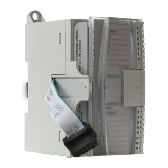
Chapter 1: Module Overview Figure 1-1 Item Description Upper panel mounting tab Lower panel mounting tab Power diagnostic LED Module door with terminal identification label Bus connector (male) Bus connector cover Flat ribbon cable with bus connector (female) Terminal block DIN rail latch Pull loop Ch 6 and Ch 7 DIP switch. -
Page 11: Section 1.7 System Overview
Chapter 1: Module Overview Section 1.7 System Overview The module communicates to the controller through the bus interface. The module also receives 5 VDC and 24 VDC power through the bus interface. An external power supply is required for all 2-wire input transmitters. NOTE 1.7.1 Module Power-up At power-up, the module performs a check of its internal circuits, memory, and... - Page 12 Chapter 1: Module Overview See the block diagram below. ASIC User’s Manual Pub. 0300247-01 Rev. D...
-
Page 13: Chapter 2 Installation And Wiring
It has been designed and tested to meet the following directive. 2.1.1 EMC Directive The 1762sc-IF4OF4 module is tested to meet Council Directive 2014/30/EU Electromagnetic Compatibility (EMC) and the following standards, in whole or in part, documented in a technical construction file: ... -
Page 14: Section 2.3 General Considerations
Chapter 2: Installation and Wiring Table 2-1 Max 5 V Max 24 V Controller Max # of IF4OF4 Modules Bus Current Bus Current ML1100 ML1200 (24 pt.) 400 ML1200 (40 pt.) 600 ML1400 (All) 1500 1500 Section 2.3 General Considerations 1762 I/O is suitable for use in an industrial environment when installed in accordance with these instructions. -
Page 15: Prevent Electrostatic Discharge
Chapter 2: Installation and Wiring 2.3.1 Prevent Electrostatic Discharge Electrostatic discharge can damage integrated circuits or semiconductors if WARNING you touch analog I/O module bus connector pins or the terminal block on the input module. Follow these guidelines when you handle the module: ... -
Page 16: Section 2.4 Mounting
Chapter 2: Installation and Wiring Section 2.4 Mounting Do not remove protective debris strip until after the module and all other WARNING equipment near the module is mounted and wiring is complete. Once wiring is complete, and the module is free of debris, carefully remove protective debris strip. -
Page 17: Panel Mounting
Chapter 2: Installation and Wiring Use DIN rail end anchors (Allen-Bradley part number 1492-EA35 or 1492- EAH35) for environments with vibration or shock concerns. Figure 2-2 For environments with extreme vibration and shock concerns, use the NOTE panel mounting method described below, instead of DIN rail mounting. 2.4.3 Panel Mounting Use the dimensional template shown below to mount the module. -
Page 18: Section 2.5 System Assembly
Chapter 2: Installation and Wiring Section 2.5 System Assembly The expansion I/O module is attached to the controller or another I/O module by means of a ribbon cable after mounting as shown below. Figure 2-4 Use the pull loop on the connector to disconnect modules. Do not pull on NOTE the ribbon cable. - Page 19 Chapter 2: Installation and Wiring Use Belden™ 8761, or equivalent, shielded wire. To ensure optimum accuracy, limit overall cable impedance by keeping a cable as short as possible. Locate the module as close to input devices as the application permits. ...
-
Page 20: Wiring Diagram
Chapter 2: Installation and Wiring Ground the shield drain wire at one end only. The typical location is as follows: For grounded thermocouples or millivolt sensors, this is at the sensor end. For insulated/ungrounded thermocouples, this is at the module end. Contact your sensor manufacturer for additional details. -
Page 21: Wiring The Finger-Safe Terminal Block
Chapter 2: Installation and Wiring 2.6.2 Wiring the Finger-Safe Terminal Block Figure 2-6 Be careful when stripping wires. Wire fragments that fall into a module WARNING could cause damage when power is applied. Once wiring is complete, ensure the module is free of all metal fragments. When wiring the terminal block, keep the finger-safe cover in place. -
Page 22: Section 2.7 Module Indicators
2-10 Chapter 2: Installation and Wiring Figure 2-7 (Door Label) Section 2.7 Module Indicators The 1762 combo module uses a single green LED to show operational status of the module. The table below shows the possible blink codes. Blink Code Description Blinks rapid The module is not in run mode. -
Page 23: Chapter 3 Configuring The 1762Sc-If4Of4 Using Rslogix 500
Chapter 3 Configuring the 1762sc-IF4OF4 Using RSLogix 500 This chapter covers the following subjects: Things you should know Module memory map Add module to Logix 500 Module configuration Reading input data Module update time Section 3.1... -
Page 24: Section 3.3 Add Module To Logix 500
Chapter 3: Configuring the 1762sc-IF4OF4 for RSLogix 500 Section 3.3 Add Module to Logix 500 The following procedure describes how to add the IF4OF4 module to the RSLogix 500 programming software. 1. Create a new RSLogix 500 project and select either a Micro 1100, 1200, or 1400 processor. -
Page 25: Section 3.4 Module Configuration
Chapter 3: Configuring the 1762sc-IF4OF4 for RSLogix 500 4. Enter the module profile data as shown in the figure below and click OK. 5. Repeat steps 1 through 4 for additional modules. Section 3.4 Module Configuration The IF4OF4 is configured using the output data table within RSLogix 500. -
Page 26: Output Channel Configuration (Channels 0 Through 3)
Chapter 3: Configuring the 1762sc-IF4OF4 for RSLogix 500 Table 3-1 (Output File) Register Function Output File (Used for Module Configuration) O:e.0 Channel 0 Data Word O:e.1 Channel 1 Data Word O:e.2 Channel 2 Data Word O:e.3 Channel 3 Data Word O:e.4... -
Page 27: Input Channel Configuration (Channels 4 And 5)
Chapter 3: Configuring the 1762sc-IF4OF4 for RSLogix 500 Table 3-3 lists the number of counts for each of the supported input channel data ranges. Table 3-3 (Output Channel Data Ranges) Output Output Value Condition Raw/Prop EU % FS Range 4..20 mA 20.40 mA... -
Page 28: Input Channel Configuration (Channels 6 And 7)
Chapter 3: Configuring the 1762sc-IF4OF4 for RSLogix 500 Table 3-4 (Configuration for Input Channels 4 and 5) To Select Make these bit settings 17 Hz Filter Frequency 4 Hz (Ignored if Display 62 Hz CJC) 470 Hz Engineering Units ×1 Engineering ×10... - Page 29 Chapter 3: Configuring the 1762sc-IF4OF4 for RSLogix 500 To Select Make these bit settings 0 to 5 V Type J TC Type K TC Type E TC Type T TC Type J TC CJC Disabled Type K TC CJC Disabled...
- Page 30 Chapter 3: Configuring the 1762sc-IF4OF4 for RSLogix 500 Input Range Input Value Condition EU ×1 EU ×10 Prop -190.00 °C Low Limit -1900 -190 -32768 0.. V 5.50 VDC High Limit 5500 32767 18201 5.00 VDC High Range 5000 32767 16383 0.00 VDC...
-
Page 31: Read Input Data
Chapter 3: Configuring the 1762sc-IF4OF4 for RSLogix 500 Section 3.5 Read Input Data The input data file contains module status information and analog input data for each of the four input channels. Analog input data is read for each channel, converted to a scaled digital value, and stored in the input file. - Page 32 3-10 Chapter 3: Configuring the 1762sc-IF4OF4 for RSLogix 500 will continue to convert analog data to the minimum “Low Limit” value. Bit is automatically reset (0) by the module when the under- range condition clears. For input data types 0-20 mA, 0-10 V, and 0-5 V, the under- range flag bits will be set when the data value is 0.
-
Page 33: Section 3.6 Module Update Time
ESD packaging (such as static-shielding / metalized bag or black conductive container). Spectrum Controls, Inc. reserves the right to void the warranty on any unit that is improperly packaged for shipment. RMA (Return Merchandise Authorization) form required for all product returns. - Page 34 3-12 Chapter 3: Configuring the 1762sc-IF4OF4 for RSLogix 500 User’s Manual Pub. 0300247-01 Rev. D...
- Page 35 Appendix A Module Specifications General Specifications Specification Value 90 mm (height) × 87 mm (depth) 40 mm (width) Height including mounting tabs is 110 mm Dimensions 3.54 in. (height) × 3.43 in. (depth) × 1.58 in. (width) Height including mounting tabs is 4.33 in. Approximate Shipping Weight (with 281 g (0.619 lbs.) carton)
- Page 36 Appendix A: Module Specifications Specification Value Recommended Cable Belden™ 8761 (shielded) Specification Value Vendor I.D. Product Type Product Code C-UL listed (under CSA C22.2 No. 142) Agency Certification UL 508 listed CE compliant for all applicable directives Class I, Division 2, Hazardous Location, Groups A, B, C, Hazardous Environment (ISA 12.12.01, C-UL under CSA C22.2 No.
- Page 37 Appendix A: Module Specifications Input Specifications Specification Value Number of Inputs 2 Current only and 2 Current/Voltage/Thermocouple A/D Converter Type Delta Sigma Common Mode Rejection 75 dB for 4 Hz and 17 Hz Filters Normal Mode Rejection 4 Hz Filter 74 dB minimum at 50 and 60 Hz 17 Hz Filter...
- Page 38 Appendix A: Module Specifications Specification Value Calibrated Accuracy Thermocouple Inputs Linearization per ITS-90 System accuracy at 25 °C (4 and 17 Hz filters): Type J (-180 °C to 1200 °C): ±1.0 degrees C maximum Type K (-200 °C to 1370 °C): ±2.0 degrees C maximum Type E (-200 °C to 1000 °C): ±1.0 degrees C maximum...
- Page 39 Appendix A: Module Specifications Specification Value Voltage Inputs System accuracy at 25 °C (4 and 17 Hz filters): ±3 mV maximum for 0-5 V inputs ±3 mV maximum for 1-5 V inputs ±10 mV maximum for 0-10 V inputs ±10 mV maximum for ±10 V inputs System accuracy at -20 °C -60 °C (4 and 17 Hz filters): ±6 mV maximum for 0-5 V inputs...
- Page 40 Appendix A: Module Specifications Output Specifications Specification Description Number of Outputs 4 channels of current or voltage Accuracy - Voltage Outputs System accuracy at 25 °C: ±20 mV maximum System accuracy at -20-60 °C: ±50 mV maximum Accuracy - Current Outputs System accuracy at 25 °C: ±50 uA maximum System accuracy at -20-60 °C: ±75 uA maximum...
- Page 41 Appendix A: Module Specifications User’s Manual Pub. 0300247-01 Rev. D...
- Page 42 Appendix A: Module Specifications User’s Manual Pub. 0300247-01 Rev. D...
- Page 43 Index A L Addressing ∙ 3‐3, 3‐9 LED ∙ 1‐4, 2‐10 B M block diagram ∙ 1‐6 Memory Map ∙ 3‐1 Module Update Time ∙ 3‐11 Mounting C DIN ∙ 2‐4 Panel ∙ 2‐5 Configuration ∙ 3‐3 Conventions N used in the manual ∙ v Noise ∙ 2‐3, 2‐8 D O Data Format ∙ 1‐3 Door Label ∙ 2‐9 Output Type ∙ 1‐1 E P EMC Directive ∙ 2‐1 Power Requirements ∙ 2‐1 power‐up ∙ 1‐5 F S Filter Frequencies ∙ 1‐3 Slot number ∙ 3‐3 G Slot Number ∙ 3‐9 Spacing Minimum ∙ 2‐4 Grounding ∙ 2‐7 T H Technical support ...
- Page 44 User’s Manual Pub. 0300247-01 Rev. D...
- Page 45 User’s Manual Pub. 0300247-01 Rev. D...
- Page 46 ©2009-2017, Spectrum Controls, Inc. All rights reserved. Specifications subject to change without notice. The Encompass logo and ControlLogix are trademarks of Rockwell Automation. Corporate Headquarters Spectrum Controls Inc. P.O. Box 6489 Bellevue, WA 98006 USA Fax: 425-641-9473 Tel: 425-746-9481 Web Site: www.spectrumcontrols.com E-mail: spectrum@spectrumcontrols.com...
Need help?
Do you have a question about the 1762sc-IF4OF4 and is the answer not in the manual?
Questions and answers