
Related Manuals for Spectrum Controls 1762sc-OF8


Summary of Contents for Spectrum Controls 1762sc-OF8
- Page 1 User’s Manual Pub. 0300246-01 Rev. B 1762 8 Channel Analog Output Module Catalog Number: 1762sc-OF8...
-
Page 2: Notice
No patent liability is assumed by Spectrum Controls with respect to the use of any of the information, products, circuits, programming, or services referenced herein. -
Page 3: Table Of Contents
Table of Contents IMPORTANT NOTES ............................ II NOTICE ................................ II LIMITED WARRANTY ............................ II CHAPTER 1 MODULE OVERVIEW ........................ 1‐1 .......................... 1‐1 ECTION ENERAL ESCRIPTION ......................... 1‐1 ECTION NPUT YPES AND ANGES ............................ 1‐1 ECTION ATA ORMATS .......................... 1‐2 ECTION ARDWARE EATURES ... - Page 4 This Manual As much as possible, we organized this manual to explain, in a task-by-task manner, how to install, configure, program, operate and troubleshoot a control system using the 1762sc-OF8. Related Documentation The table below provides a listing of publications that contain important information about Allen-Bradley PLC systems.
- Page 5 Conventions Used in This Manual The following conventions are used throughout this manual: Bulleted lists (like this one) provide information not procedural steps. Numbered lists provide sequential steps or hierarchical information. Italic type is used for emphasis ...
- Page 6 MicroLogix™ 1200 8 Ch Output Module User’s Manual Pub. 0300246-01 Rev. B...
-
Page 7: Chapter 1 Module Overview
Chapter 1 Module Overview This chapter describes the 1762sc-OF8 output module. The module provides 8 analog output channels that can be configured for current or voltage. Included is information about: General description Output types and ranges Data Formats ... -
Page 8: Section 1.4 Hardware Features
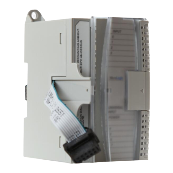
MicroLogix™ 1200 IO 8 Ch Output Module Section 1.4 Hardware Features Module configuration is done via the controller’s programming software. The module configuration is stored in the memory of the controller. Refer to your controller’s user manual for more information. The illustration below shows the module’s hardware features. -
Page 9: Section 1.5 System Overview
Chapter 1: Module Overview Table 1-1 (LED Blink Codes) Blink Code Description Rapid Blink PLC not in run mode, or no valid module configuration present Solid Module is in run mode (Normal Operation) Factory calibration in progress Factory calibration invalid Module is in command mode Section 1.5 System... -
Page 10: Module Operation
MicroLogix™ 1200 IO 8 Ch Output Module 1.5.2 Module Operation When the module receives a new command value from the output image, the module’s circuitry converts the digital value to an analog current/voltage signal using a DAC (Digital to Analog Converter). See the block diagram below. User’s Manual Pub. -
Page 11: Chapter 2 Installation And Wiring
2.1.1 EMC Directive The 1762sc-OF8 module is tested to meet Council Directive 89/336/EEC Electromagnetic Compatibility (EMC) and the following standards, in whole or in part, documented in a technical construction file: ... -
Page 12: General Considerations
MicroLogix™ 1200 IO 8 Ch Output Module 5 VDC 24 VDC 30 mA 250 mA @ 18.7V, 195mA @ 24V Use the table below to determine the maximum number of OF8 modules that can be installed in a MicroLogix system. Table 2-1 Max 5V Max 24V... -
Page 13: Prevent Electrostatic Discharge
Chapter 2: Installation and Wiring 2.3.2 Prevent Electrostatic Discharge Electrostatic discharge damage integrated circuits semiconductors if you touch analog I/O module bus connector pins or the terminal block on the input module. Follow these guidelines when Attention you handle the module: ... -
Page 14: Minimum Spacing
MicroLogix™ 1200 IO 8 Ch Output Module 2.4.1 Minimum Spacing Maintain spacing from enclosure walls, wireways, adjacent equipment, etc. Allow 50.8 mm (2 in.) of space on all sides for adequate ventilation, as shown: Figure 2-1 Note: 1762 expansion I/O may be mounted horizontally only. During panel or DIN rail mounting of all devices, be sure that all debris (metal chips, wire strands, etc.) is kept from falling into the module. -
Page 15: Panel Mounting
Chapter 2: Installation and Wiring Figure 2-2 Note: For environments with extreme vibration and shock concerns, use the panel mounting method described below, instead of DIN rail mounting. 2.4.3 Panel Mounting Use the dimensional template shown below to mount the module. The preferred mounting method is to use two M4 or #8 Pan Head screws per module. -
Page 16: Section 2.6 Field Wiring Connections
MicroLogix™ 1200 IO 8 Ch Output Module Figure 2-4 Note: Use the pull loop on the connector to disconnect modules. Do not pull on the ribbon cable. EXPLOSION HAZARD In Class I, Division 2 applications, the bus connector must be fully seated and the bus connector cover must be snapped in Attention place. -
Page 17: Wiring Diagram
Chapter 2: Installation and Wiring USE SUPPLY WIRES SUITALE FOR 20°C ABOVE SURROUNDING AMBIENT Attention UTILISER DES FILS D’ALIMENTATION QUI CONVIENNENT A UNE TEMPERATURE DE 20°C AU-DESSUS DE LA TEMPERATURE AMBIANTE Attention Grounding This product is intended to be mounted to a well-grounded mounting surface such as a metal panel. - Page 18 MicroLogix™ 1200 IO 8 Ch Output Module Shield Load OUT 0 RTN 0 OUT 1 RTN 1 OUT 2 RTN 2 OUT 3 RTN 3 RTN 4 OUT 4 RTN 5 OUT 5 RTN 6 OUT 6 RTN 7 OUT 7 Note: All return terminals are electrically tied together, but each output should use its own associated return terminal for best accuracy.
-
Page 19: Wiring The Finger-Safe Terminal Block
Chapter 2: Installation and Wiring 2.6.2 Wiring the Finger-Safe Terminal Block Figure 2-6 Be careful when stripping wires. Wire fragments that fall into a module could cause damage when power is applied. Once wiring is complete, ensure the module is free of all metal fragments. Attention When wiring the terminal block, keep the finger-safe cover in place. -
Page 20: Section 2.7 Module Indicators
2-10 MicroLogix™ 1200 IO 8 Ch Output Module Figure 2-7 (Door Label) Section 2.7 Module Indicators The 1762 output module uses a single green LED to show operational status of the module. The LED will illuminate solid when the PLC is in run mode and the module properly configured. -
Page 21: Section 3.1 Things You Should Know
Chapter 3 Configuring the 1762sc-OF8 Using RSLogix 500 This chapter covers the following subjects: Things you should know Module memory map Add module to Logix 500 Module configuration Module status Configuration Ladder Sample Section 3.1... -
Page 22: Section 3.3 Add Module To Logix 500
MicroLogix™ 1200 IO 8 Ch Output Module Section 3.3 Add Module to Logix 500 The following procedure describes how to add the OF8 module to the RSLogix 500 programming software. 1.) Create a new RSLogix 500 project and select either a Micro 1100, 1200, or 1400 processor. -
Page 23: Section 3.4 Module Configuration
Chapter 3: Configuring the 1762sc-OF8 for RSLogix 500 5.) Repeat steps 1 through 4 for additional modules. Section 3.4 Module Configuration The OF8 module is configured using a process that employs the input and output files. The following flow chart describes the configuration process. -
Page 24: Output Data File (Command Mode)
MicroLogix™ 1200 IO 8 Ch Output Module 3.4.1 Output Data File (Command Mode) The output data file is used to configure each channel for the OF8 as well as control the output signal of each channel. Use the addressing scheme below to locate the 8 output words needed to configure the module. - Page 25 Chapter 3: Configuring the 1762sc-OF8 for RSLogix 500 2) Validate Command: If the Fixed Words are valid, the Command word will be checked. If it is not set to a valid command, an error will be reported. Initially the module only checks for the Unlock command.
- Page 26 MicroLogix™ 1200 IO 8 Ch Output Module Table 3-3 (Data Words 1 through 4) To Select Channels 1, 3, 5, or 7 Channels 0, 2,4 or 6 4 to 20 mA 0 to 20 mA -10 to 10 V Output 0 to 10 V Type 1 to 5 V...
-
Page 27: Output Data File (Normal Run Mode)
Chapter 3: Configuring the 1762sc-OF8 for RSLogix 500 Table 3-4 (Data Format) Output Range Output Value Condition Raw/Prop % FS 4..20mA 20.40 mA High Limit 32767 20400 16793 10250 20.00 mA High Range 31176 20000 16383 10000 4.00 mA Low Range... - Page 28 MicroLogix™ 1200 IO 8 Ch Output Module Figure 3-3 (Input Addressing Scheme) /O located on the controller (embedded I/O) is slot 0. I/O added to the controller (expansion I/O) begins with slot 1. The layout for the input data file is shown below. Table 3-5 (Input Data File) Input Word Normal Run Mode...
-
Page 29: Input Data File (Normal Run Mode)
Chapter 3: Configuring the 1762sc-OF8 for RSLogix 500 Table 3-7 (Response Codes) Name Value Description Success 0x0000 The command was completed successfully. Invalid Command 0xF001 An invalid command code was issued. A command was issued before the Unlock was Locked 0xF002 given. -
Page 30: Configuration Ladder Sample
3-10 MicroLogix™ 1200 IO 8 Ch Output Module Table 3-8 (Input Words - Normal Run Mode) Word 13 12 11 General Status (Word 0) I:e.0 S5 S4 S3 S1 S0 Output Status (Word 1) I:e.1 LD3 U3 O3 LD2 U2 O2 LD1 U1 O1 LD0 U0 O0 Output Status (Word 2) I:e.2... - Page 31 Chapter 3: Configuring the 1762sc-OF8 for RSLogix 500 3-11 User’s Manual Pub. 0300246-01 Rev. B...
- Page 32 3-12 MicroLogix™ 1200 IO 8 Ch Output Module User’s Manual Pub. 0300246-01 Rev. B...
- Page 33 Chapter 3: Configuring the 1762sc-OF8 for RSLogix 500 3-13 User’s Manual Pub. 0300246-01 Rev. B...
- Page 34 3-14 MicroLogix™ 1200 IO 8 Ch Output Module User’s Manual Pub. 0300246-01 Rev. B...
-
Page 35: Appendix A Module Specifications
Appendix A Module Specifications General Specifications Specification Value 90 mm (height) x 87 mm (depth) x 40 mm (width) height including mounting tabs is 110 mm Dimensions 3.54 in. (height) x 3.43 in. (depth) x 1.58 in. (width) height including mounting tabs is 4.33 in. Approximate Shipping 279g (0.615 lbs.) Weight (with carton) - Page 36 MicroLogix™ 1200 IO 8 Ch Output Module Specification Value Product Code C-UL listed (under CSA C22.2 No. 142) Agency UL 508 listed Certification CE compliant for all applicable directives Class I, Division 2, Hazardous Location, Groups A, B, Hazardous C, D Environment (ISA 12.12.01, C-UL under CSA C22.2 No.
- Page 37 Appendix A: Specifications Output Specifications Specification Description Accuracy - Voltage System accuracy at 25° C: ± 20 mV maximum Outputs System accuracy at -20-60°C: ± 50 mV maximum Accuracy - Current System accuracy at 25° C: ± 50 uA maximum Outputs System accuracy at -20-60°C: ±...
- Page 38 MicroLogix™ 1200 IO 8 Ch Output Module User’s Manual Pub. 0300246-01 Rev. B...
- Page 39 A L Addressing ∙ 3‐4, 3‐7, 3‐9 LED ∙ 1‐2, 2‐10 Low Voltage Directive ∙ 2‐1 B M block diagram ∙ 1‐4 Memory Map ∙ 3‐1 Mounting C DIN ∙ 2‐4 Panel ∙ 2‐5 Configuration ∙ 3‐4 N D Noise ∙ 2‐3, 2‐7 Data Format ∙ 1‐1 Door Label ∙ 2‐9 O E Output Type ∙ 1‐1 EMC Directive ∙ 2‐1 P G Power Requirements ∙ 2‐1 power‐up ∙ 1‐3 Grounding ∙ 2‐7 S H Slot number ∙ 3‐4 Slot Number ∙ 3‐8 Hazardous Location ∙ 2‐2 Spacing Minimum ∙ 2‐4 I W Input Data ∙ 3‐7 Wiring Diagram ∙ 2‐7 User’s Manual Pub. 0300246-01 Rev. B...
- Page 40 User’s Manual Pub. 0300246-01 Rev. B...
- Page 41 In the unlikely event that the module should need to be returned to Spectrum Controls, please ensure that the unit is enclosed in approved ESD packaging (such as static-shielding / metalized bag or black conductive container).
- Page 42 ©2009, Spectrum Controls, Inc. All rights reserved. Specifications subject to change without notice. The Encompass logo and ControlLogix are trademarks of Rockwell Automation. Corporate Headquarters Spectrum Controls Inc. P.O. Box 6489 Bellevue, WA 98006 USA Fax: 425-641-9473 Tel: 425-746-9481 Web Site: www.spectrumcontrols.com E-mail: spectrum@spectrumcontrols.com...
Need help?
Do you have a question about the 1762sc-OF8 and is the answer not in the manual?
Questions and answers