Table of Contents
Advertisement
Quick Links
Advertisement
Table of Contents

Related Manuals for Spectrum Controls SLC 500


Summary of Contents for Spectrum Controls SLC 500
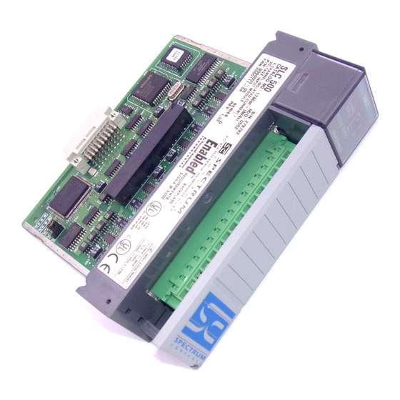
- Page 1 User’s Manual Pub. 0300128-04 Rev. A...
-
Page 2: Important Notes
No patent liability is assumed by Spectrum Controls, Inc. with respect to the use of any of the information, products, circuits, programming, or services referenced herein. -
Page 3: Table Of Contents
Table of Contents IMPORTANT NOTES ............................... II LIMITED WARRANTY .............................. II CHAPTER 1 MODULE OVERVIEW ......................... 1-1 1.1 G ......................1-1 ECTION ENERAL EATURES ENEFITS 1.2 D .......................... 1-2 ECTION ETAILED PECIFICATIONS CHAPTER 2 INSTALLATION AND WIRING ......................2-1 2.1 P ...................... - Page 4 SLC 500™ Isolated Analog Output Modules 4.5 I I/O E ....................... 4-3 ECTION NTERPRETING RROR ODES 4.6 T ........................... 4-4 ECTION ROUBLESHOOTING CHAPTER 5 MAINTAINING YOUR MODULE AND ENSURING SAFETY ..............5-1 5.1 P ........................5-1 ECTION REVENTIVE AINTENANCE 5.2 S ...........................
- Page 5 Use this guide if you design, install, program, or maintain a control system that uses Allen-Bradley Small Logic Controllers. You should have a basic understanding of SLC 500 products. You should also understand electronic process control, and the ladder program instructions required to generate the electronic signals that control your application.
- Page 6 SLC 500™ Isolated Analog Output Modules Allen-Bradley Refer to this Document Pub. No. Allen-Bradley Advanced Programming 1747-6.11 Software (APS) Reference Manual Getting Started Guide for Advanced 1747-6.3 Programming Software (APS) SLC 500 Software Programmers’ Quick ABT-1747-TSG001 Reference Guide Allen-Bradley HHT (Hand-Held...
- Page 7 SLC 500™ Isolated Analog Output Modules Actions ou situations risquant d’entraîner des blessures pouvant être ATTENTION mortelles, des dégâts matériels ou des pertes financières. Les messages « Attention » vous aident à identifier un danger, à éviter ce danger et en discerner les conséquences.
- Page 8 SLC 500™ Isolated Analog Output Modules User’s Manual Pub. 0300128-04 Rev. A...
-
Page 9: Chapter 1 Module Overview
Chapter 1 Module Overview The 1746sc-INO4i provides four isolated channels of current outputs, while the 1746sc-INO4vi provides four isolated channels of current or voltage outputs (in any combination). In both modules, the voltage and/or current ranges are independently configurable for each channel. These modules also provide new, advanced features to make your control systems more dependable and flexible. -
Page 10: Section 1.2 Detailed Specifications
Chapter 1: Module Overview Section 1.2 Detailed Specifications Table 1-1. Electrical Specifications-Module Description Specification Backplane Current Consumption (maximum) 1746sc-INO4i 120 mA at 5 VDC 250 mA at 24 VDC 1746sc-INO4vi 120 mA at 5 VDC 250 mA at 24 VDC Backplane Power Consumption 0.6 W (typical) - Page 11 Chapter 1: Module Overview Description Specification Output Impedance Current Outputs Greater than 1 Mohm Voltage Outputs—INO4vi only Less than 1.0 Ohm Load Range Current Outputs 0 to 500 Ohm Voltage Outputs—INO4vi only 1 kohm and greater Max. Current, Voltage Mode- 10 mA INO4vi only Output Step Response Time...
- Page 12 Chapter 1: Module Overview Section 1.3 Regulatory Requirements Compliance Industry Standards Standards UL 61010-2-201 Safety Requirements for Electrical Equipment for Measurement, Control, and Laboratory Use - Part 2-201: Particular Requirements for Control Equipment (NRAQ, NRAQ7) UL Safety CAN/CSA C22.2 No. 61010-1-12 (Safety Requirements for Electrical Equipment for Measurement, Control, and Laboratory Use –...
-
Page 13: Chapter 2 Installation And Wiring
Chapter 2 Installation and Wiring This chapter will cover: • Avoiding electrostatic damage. • Determining power requirements. • Setting the DIP switch. • Selecting a rack slot. • Inserting your module into the rack. Wiring your module. • Although your module has a jumper on its printed circuit board, this NOTE jumper is for the manufacturer’s use only. -
Page 14: Section 2.1 Prevent Electrostatic Discharge
Chapter 2: Installation and Wiring • IEEE Standard 142-1982, Recommended Practices for Grounding of Industrial and Commercial Power Systems Noise Reduction Techniques in Electronic Systems, by Henry W. Ott; • published by Wiley-Interscience of New York in 1976 Section 2.1 Prevent Electrostatic Discharge... -
Page 15: Section 2.2 Power Requirements
Chapter 2: Installation and Wiring Electrical Equipment for Measurement, Control, and Laboratory Use - Part 2- 201: Particular Requirements for Control Equipment. For specific information required by EN 61010-2-201, see the appropriate sections in this publication, as well as the following Allen-Bradley publications: •... -
Page 16: Section 2.4 Selecting A Rack Slot
Chapter 2: Installation and Wiring The switch, SW1, is located in the bottom corner of the module’s large circuit board. Section 2.6 Selecting a Rack Slot Two factors determine where you should install your module in the rack: ambient temperature and electrical noise. When selecting a slot for your module, try to position your module: In a rack close to the bottom of the enclosure (where the air is cooler). -
Page 17: Section 2.6 Inserting Your Module Into The Rack
WARNING Before installing or removing your module, always disconnect power from the SLC 500 system and from any other source to the module (in other words, do not “hot swap” your module), and disconnect any devices wired to the module. -
Page 18: Section 2.7 Wiring Your Module
Before wiring the terminal block, take some time to plan your system: Ensure that the SLC 500 system is installed in a NEMA-rated enclosure • and that the SLC 500 system is properly grounded. - Page 19 Chapter 2: Installation and Wiring 5 mm) of insulation away to expose the end of each wire. 4. At one end of the cable, twist the drain wire and foil shield together, bend them away from the cable, and apply shrink wrap. 5.
- Page 20 Chapter 2: Installation and Wiring A system may malfunction due to a change in its operating environment. After installing and wiring your module, check system operation. See the Allen-Bradley system Installation and Operation Manual for more information. Figure 2-2. Wiring diagrams (showing differential outputs) User’s Manual Pub.
-
Page 21: Chapter 3 Configuring The 1746Sc-Ino4I
Chapter 3 Configuring the 1746sc- INO4I This chapter covers the following subjects: Introduction. • About Communications. • About Channel Update Time. • Configuring Your Module. • Reading Input Data. • Getting Technical Assistance. • Declaration of Conformity. • Section 3.1 Introduction This chapter will describe how your module works, and how to configure the module. -
Page 22: Section 3.3 Configuration
Chapter 3: Configuring the 1746sc-INO4I Section 3.3 Configuration Channel Update Time For an output module, channel update time is the time required for the module to convert the channel data received from the processor to an analog output signal at the terminals. -
Page 23: Entering Your Module's Id Code
Chapter 3: Configuring the 1746sc-INO4I UNEXPECTED EQUIPMENT OPERATION WARNING Always understand the implications of disabling a module before using the slot disable feature. Failure to observe this precaution can cause unintended equipment operation When you disable an output module’s slot, the module holds its outputs in their last state. -
Page 24: Output Image
Chapter 3: Configuring the 1746sc-INO4I Figure 3-2. Output and Input Words Example – If you want to reconfigure channel 2 on your module, and it is in slot 4 of the SLC chassis, you modify the configuration word at address O:4.5. Alternatively, if you want to obtain the status of channel 2, you check the status word at address I:4.6. -
Page 25: Input Image
Chapter 3: Configuring the 1746sc-INO4I data values to analog output signals, if the User-Defined Scale data format is selected. For more information on the user-defined scale and output data limits, see Optional: Setting the Output Data Limits (or User-Defined Scale), later in this chapter. -
Page 26: Output Channel Enable (Configuration Bits 0 And 8)
Chapter 3: Configuring the 1746sc-INO4I Table 3-3. Channel Configuration Word Details, Output Words 4 and 5 (O:e:4 and O:e:5) Output Channel Enable (configuration bits 0 and 8) Use this bit to enable or disable a channel. To minimize update times, disable any unused channels. - Page 27 Chapter 3: Configuring the 1746sc-INO4I These data formats are defined in the following table: Selected Data Value (counts) Corresponding Signal Data Format Output Min. to Max. Min. Max. Range Engineering Units ±10 V -10250 +10250 -10.25 V - +10.25 V 0–10 V -500 +10250...
-
Page 28: Reset Output Or Hold Last Value On Fault (Configuration Bits 7 And 15)
Chapter 3: Configuring the 1746sc-INO4I Selected Data Value (counts) Corresponding Signal Data Format Output Min. to Max. Min. Max. Range 0–10 V -0.50 V - +10.25 V 0–5 V -0.50 V - +5.50 V 1–5 V See footnote +0.50 V - +5.50 V 0–20 mA 0.0 mA - +20.5 mA 0–21 mA... -
Page 29: Output Data Limits
Chapter 3: Configuring the 1746sc-INO4I Output Data Limits For added safety, the 1746sc-INO4i and 1746sc-INO4vi output modules let you define limits for the values in the output data words of all four channels. These data limits, in turn, limit the output signals that your module provides. When an output data word exceeds the data limit, the output value is truncated to the limit. -
Page 30: User-Defined Scale
3-10 Chapter 3: Configuring the 1746sc-INO4I Your module will now limit the output signal as shown below. Note that whenever the requested output data values meet or attempt to exceed the output data limits, your module sets bits 10 or 11 in the channel status word to indicate a limit error. -
Page 31: Controlling Each Output Channel's Signal
Chapter 3: Configuring the 1746sc-INO4I 3-11 = high limit of signal value high ∆S = S high D = data value (user-defined scale) = low value of user-defined scale = high value of user-defined scale high ∆U = U high Example –... -
Page 32: Monitoring Each Output Channel
3-12 Chapter 3: Configuring the 1746sc-INO4I Monitoring Each Output Channel The requested output data values are reflected in words 0 through 3 of the input image file (addresses I:e.0 through I:e.3). Whenever a channel is disabled, its data word is reset to zero. Checking Each Output Channel’s Configuration Status Words 4 through 7 of the input image file (addresses I:e.4 through I:e.7) reflect the configuration and status of each channel. -
Page 33: Output Data Limiting Enabled (Status Bit 8)
Chapter 3: Configuring the 1746sc-INO4I 3-13 Channel status word details, Input Words 4 through 7 (I:e.4 through I:e.7 are defined in the following table: Table 3-4 Channel Status Word Details, Input Words 4 through 7 (I:e.4 through I:e.7) The first 8 status bits reflect the settings in the channel configuration word. The remaining status bits flag the various errors that the module can detect. -
Page 34: Operating Temperature Error (Status Bit 9)
This bit is set to one whenever your module detects a recoverable channel error, such as an invalid configuration word or an operating temperature error (see above), or while the SLC 500 processor is resetting. This bit is reset to zero when the error no longer exists. -
Page 35: Chapter 4 Testing Your Module
• Troubleshooting. • Before testing your module, test your SLC 500 system using the procedures described in your Allen-Bradley system Installation & Operation Manual. Important — If your module appears to be functioning, but the terminals aren’t providing an output signal, the 24 VDC power source (backplane or external) may not be providing enough current (250 mA). -
Page 36: Section 4.4 Interpreting The Led Indicators
Discontinue testing until you can get the LED to illuminate. The most probable reasons for the LED not illuminating are: The SLC 500 system is not receiving power from its power supply. • The rest of the SLC 500 system is not receiving power. - Page 37 Either the power is off, the module is powering up, or a module fault occurred. Cycle power. If the condition persists, call your local distributor or Spectrum Controls for assistance. Section 4.5 Interpreting I/O Error Codes I/O error codes appear in word S:6 of the SLC processor status file. The first two digits of the error code identify the slot (in hexadecimal) with the error.
- Page 38 Chapter 4: Testing your Module Section 4.6 Troubleshooting Figure 4-2. Problem Resolution Flowchart User’s Manual Pub. 0300128-04 Rev. A...
- Page 39 The printed circuit boards of your module must be protected from dirt, oil, moisture, and other airborne contaminants. To protect these boards, install the SLC 500 system in an enclosure suitable for its operating environment. Keep the interior of the enclosure clean, and whenever possible, keep the enclosure door closed.
- Page 40 Controls Inc., please ensure that the unit is enclosed in approved ESD packaging (such as static-shielding/metallized bag or black conductive container). Spectrum Controls, Inc. reserves the right to void the warranty on any unit that is improperly packaged for shipment.
- Page 41 User’s Manual Pub. 0300266-04 Rev. A...
- Page 42 ©1997-2021, Spectrum Controls, Inc. All rights reserved. Specifications subject to change without notice. The Encompass logo and SLC 500 are trademarks of Rockwell Automation. Corporate Headquarters Spectrum Controls Inc. 1705 132nd Avenue NE, Bellevue, WA 98005 USA Fax: 425-641-9473 Tel: 425-746-9481 Web Site: www.spectrumcontrols.com...
Need help?
Do you have a question about the SLC 500 and is the answer not in the manual?
Questions and answers