Table of Contents
Advertisement
Quick Links
Advertisement
Table of Contents

Related Manuals for Spectrum Controls 1756-CTR8


Summary of Contents for Spectrum Controls 1756-CTR8
- Page 1 Owner’s Guide 0300310-02A...
- Page 2 No patent liability is assumed by Spectrum Controls, Inc. with respect to the use of any of the information, products, circuits, programming, or services referenced herein.
- Page 3 Table of Contents IMPORTANT NOTES ............................... II TABLE OF CONTENTS ............................. III PREFACE ................................V CHAPTER 1 MODULE OVERVIEW ......................... 1-1 ........................1-1 ECTION ENERAL ESCRIPTION ............................1-1 ECTION NPUT YPES ......................... 1-1 ECTION ARDWARE EATURES ..........................1-2 ECTION IAGNOSTIC ..........................
-
Page 4: Table Of Contents
ControlLogix™ CTR8 Counter Module ..............4-6 ECTION ONFIGURING ODULE TTRIBUTES ONFIGURATION ........................4-6 ECTION HANNEL PECIFIC ............................4-7 ECTION ............................. 4-8 ECTION TATUS CHAPTER 5 CONFIGURATION, DATA, AND STATUS TAGS ..................5-1 ..................5-1 ECTION ONFIGURATION ATA TO THE ODULE ......................... - Page 5 ControlLogix™ CTR8 Counter Module Preface This is a re-issue of an existing manual, with some corrections, and NOTE updated Certification information. Read this introduction to familiarize you with the rest of the owner’s guide. This preface covers the following topics: •...
- Page 6 ControlLogix™ CTR8 Counter Module Allen-Bradley Refer to this Document Allen-Bradley Pub. No. ControlLogix Ethernet 1756-ENET 1756-6.5.1 Communication Interface Module User Manual Rockwell Automation Technical Support For technical support, please contact your local Rockwell Automation TechConnect Office for all Spectrum products. Contact numbers are as follows: •...
- Page 7 ControlLogix™ CTR8 Counter Module Identifies information that is critical for successful application and NOTE understanding of the product. Owner’s Guide 0300199-01 Rev. D...
- Page 8 viii ControlLogix™ CTR8 Counter Module Owner’s Guide 0300199-01 Rev. D...
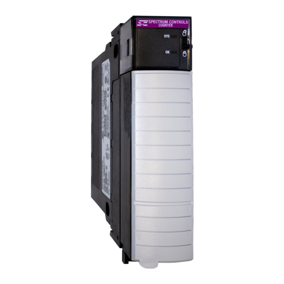
- Page 9 Chapter 1 Module Overview This chapter describes the 1756sc-CTR4 and 1756sc-CTR8 and the conformally coated 1756sc-CTR4/1756sc-CTR8K counter modules and explains how the ControlLogix controller reads analog input data from the modules. Other than the conformal coating, the modules are identical so all information applicable to the earlier modules applies to the K versions.
- Page 10 Chapter 1: Module Overview module is configured through RSLogix 5000 software, defining input type, counter control, and signal filtering. Table 1-1. Hardware Features Hardware Function OK LED Displays communication and fault status of the module. Cal LED Displays a fault condition. Side Label (Nameplate) Provides module information.
- Page 11 Chapter 1: Module Overview FPGA. The FPGA reads the input signals and converts them to counter and rate, and then presents them in floating point values. The input circuitry also supports gate inputs, allowing you to disable and control counter operation. Cable length should be kept to a minimum.
- Page 12 Chapter 1: Module Overview Owner’s Guide 0300199-01 Rev. D...
- Page 13 Chapter 2 Installing the ControlLogix 1756sc-CTR8 Module Use this guide to install and wire your ControlLogix 1756sc-CTR8 module. The 1756sc-CTR8 Module mounts to an Allen-Bradley ControlLogix 1756 Controller chassis. The module uses a Removable Terminal Block (RTB) to connect all field-side wiring.
- Page 14 Chapter 2: Installing a ControlLogix 1756sc-CTR8-SC Module If this product bears the CE marking, it is approved for installation within the European Union and EEA regions. It has been designed and tested to meet the following directives. This product is tested to meet Council Directive 2014/30/EU Electromagnetic Compatibility (EMC) and the following standards, in whole or in part, documented in a technical construction file: EN 61000-6-4 Electromagnetic compatibility (EMC)–Part 6-4: Generic...
- Page 15 Chapter 2: Installing a ControlLogix 1756sc-CTR8-SC Module This equipment is classified as open equipment and must be installed (mounted) in an enclosure during operation as a means of providing safety protection. The conformally coated versions of the module meet or exceed the ANSI/ISA 71.04.2013 G3 Environment standard.
- Page 16 Chapter 2: Installing a ControlLogix 1756sc-CTR8-SC Module Hazard of electrical arcing when removing or inserting the module WARNING while power is applied to the rack. This module is designed so you can remove and insert it under backplane power and field-side power. When you remove or insert a module while field-side power is applied, you may cause an electrical arc.
- Page 17 Chapter 2: Installing a ControlLogix 1756sc-CTR8-SC Module Key the RTB to prevent inadvertently making the wrong wire connections to your module. Use a unique keying pattern for each module. You can use a minimum of one key. When the RTB mounts onto the module, keying positions will match up. For example, if you place a U-shaped keying band in position #4 on the module, you cannot place a wedge-shaped tab in #4 on the RTB or your RTB will not mount on the module.
- Page 18 Chapter 2: Installing a ControlLogix 1756sc-CTR8-SC Module Follow these guidelines to wire your input signal cables: • Power, input, and output (I/O) wiring must be in accordance with Class I, Division 2 wiring methods [Article 501-4(b) of the National Electrical Code, NFPA 70] and in accordance with the authority having jurisdiction.
- Page 19 Chapter 2: Installing a ControlLogix 1756sc-CTR8-SC Module To prepare and connect cable leads and drain wires, follow these steps: 1. At each end of the cable, strip some casing to expose individual wires. 2. Trim signal wires to 5-inch lengths beyond the cable casing. Strip about 3/16 inch (4.76 mm) of insulation to expose the ends of the wires.
- Page 20 Chapter 2: Installing a ControlLogix 1756sc-CTR8-SC Module The following figure shows the general terminal block layout. The input signal type determines which pins are used: Owner’s Guide 0300199-01 Rev. D...
- Page 21 Chapter 3 Operation Within the ControlLogix System This chapter describes how the 1756sc-CTR8 analog module works within the ControlLogix system. This chapter covers: • Ownership and connections to the module. • Direct connections. • Listen only mode. Configuration changes with multiple owners. •...
- Page 22 Chapter 3: Operation Within the ControlLogix System Follow these general guidelines when configuring I/O modules: 1. Configure all I/O modules for a given controller using RSLogix 5000 and download that information to the controller. 2. If the I/O configuration data references a module in a remote chassis, run RSNetWorx.
- Page 23 Chapter 3: Operation Within the ControlLogix System When a module resides in the same chassis as the owner-controller, the following two configuration parameters will affect how, and when, the input module multicasts data: Real Time Sample (RTS) configured via Real Time Sample tag. •...
- Page 24 Chapter 3: Operation Within the ControlLogix System Even though data may be transferred at the RPI rate, the data will be NOTE identical to the previous RTS data transfer. If an input module resides in a networked chassis, the role of the RPI and the module’s RTS behavior change slightly with respect to getting data to the owner.
- Page 25 Chapter 3: Operation Within the ControlLogix System Choosing a Listen-Only mode option allows the controller and module to establish communications without the controller sending any configuration data. In this instance, another controller owns the module being listened to. IMPORTANT: Controllers using the Listen-Only mode continue to NOTE receive data multicast from the I/O module as long as a connection between an owner and I/O module is maintained.
- Page 26 Chapter 3: Operation Within the ControlLogix System Exercise caution when changing an input modules’ configuration data in a multiple owner scenario. When the configuration data is changed in one of the owners, for example, Controller A, and sent to the module, that configuration data is accepted as the new configuration for the module.
- Page 27 Chapter 4 Programming Your Module This chapter explains how to program your module in the ControlLogix system. It also describes how the module’s input configuration are incorporated into your ladder logic program. Topics discussed include: Import the module’s configuration profile. •...
- Page 28 Chapter 4: Programming Your Module Step 1: Open the Sample Project: Step 2: Open your new project as follows: 1. Drag and drop the CTR8 user-defined data types from the sample project into your project. There are three CTR8 user defined data types that need to be moved: •...
- Page 29 Chapter 5: Configuration, Data, and Status Tags These can only be moved one at a time. NOTE Step 3: Drag and drop the controller configuration tags from the sample project into your project as follows: 1. Right click on the Controller Tags item of the sample project and select edit.
- Page 30 Chapter 4: Programming Your Module CTR8_Config and CTR8_Input contain the configuration, data, and status NOTE tags for the CTR8 module. The other tags are used for performing various functions with your module via ladder logic. Be sure all tags are displayed before moving them. Select Display All from NOTE the Edit drop down window.
- Page 31 Chapter 5: Configuration, Data, and Status Tags Step 4: Create a new ladder logic routine in your project. 1. In your project, right mouse-click on the MainRoutine item and select New Routine. CTR8 was entered in the example above. 2. Double click on the MainRoutine item in the sample project and then double click on the added new routine in your project to display their corresponding ladder logic.
- Page 32 Chapter 4: Programming Your Module This completes the installation of module in the system. The module has settings that are global and channel specific. These are accessed via the controller tags. Specific information regarding these tag settings may be found in Chapter 5. These settings control channel-specific behavior such as input type, range, filter frequency, units, and alarms.
- Page 33 Chapter 5: Configuration, Data, and Status Tags Specific information regarding these tags may be found in Chapter 5: These tags represent the process data values in their final form: Owner’s Guide 0300199-01 Rev. D...
- Page 34 Chapter 4: Programming Your Module These tags report module status such as alarm conditions, faults, and errors: Owner’s Guide 0300199-01 Rev. D...
-
Page 35: Tags
Chapter 5 Configuration, Data, and Status Tags Read this chapter to: • Send configuration data to the module. • Configure global module properties. • Configure each input channel. • Check each input channel’s data. • Check module and individual channel status. This chapter outlines the detailed settings for the 1756sc-CTR8. -
Page 36: Section 5.4 Uni -Directional
Chapter 5: Configuration, Data, and Status Tags The following Global Module Settings and Channel-Specific Settings sections allow custom configuration of the module. These tags can be found within the CTR8_config controller tags. [x] designates the channel number. (C) designates the value may be changed during module operation CountLimit[x] 0 - 16777215 FLOAT (C) Designates the channel rollover value. - Page 37 Chapter 5: Configuration, Data, and Status Tags With this configuration, the input increments in an upward direction. All 8 channels may be configured in the unidirectional mode. Every clock pulse will increment the counter on the rising edge. The direction of the counter may be inverted by setting the Count NOTE Direction bit described in the Configuration chapter.
- Page 38 Chapter 5: Configuration, Data, and Status Tags If B leads A, the counter decrements. However, the counter changes value on the rising and falling edges of inputs A and B. The counter increments four times per quadrature cycle. This mode determines how the gate behavior effects counter behavior: 0 = no store mode.
- Page 39 Chapter 5: Configuration, Data, and Status Tags StorageMode = 2 - Store/Wait/Resume. StorageMode = 3 - Store-Reset/Wait/Start. StorageMode = 4 - Store-Reset/Start. InputRange[x] 0,1 This setting determines the threshold where the counter will begin to trigger. Select the range that is best suited to your sensor’s range: 0 = AC 50 mVpp threshold.
- Page 40 Chapter 5: Configuration, Data, and Status Tags value can also be multiplied. If you multiply two values together, the output should remain within the maximum value of the Real type. Most M factors will be within ±5% of 1.0000. MFactor[x] 0 - 1×1032 FLOAT The R scale factor can be used for scaling of the output frequency.
- Page 41 Chapter 5: Configuration, Data, and Status Tags Stoponlimit[x] 0,1 BOOL (C) Designates what channel 0 will do when it counts up to the count_limit: 0 = roll over. 1 = stop at the limit. Disable[x] BOOL Enable the counter for channel [x]: 0 = enable.
- Page 42 Chapter 5: Configuration, Data, and Status Tags The following data tags are preceded by the tag name CTR8_Input.ChannelData[x] where x is the channel number 0-7. CommStatus 0,65535 DINT Displays module connection status: 0 = module is connected. 65535 = module is not connected. Count[x] 0-16777215 FLOAT...
- Page 43 Chapter 5: Configuration, Data, and Status Tags GateState[x] BOOL Displays the channel Z state: 0 = Gate is not active. 1 = Gate is active. CounterInputState[x] 0,1 BOOL This echoes the state of the input. Note that this is also impacted by the gate and/or enable line. NOTE CountDirection[x] BOOL...
- Page 44 5-10 Chapter 5: Configuration, Data, and Status Tags Owner’s Guide 0300199-01 Rev. D...
-
Page 45: Programming
Chapter 6 Programming Examples Earlier chapters explained how the tag configuration defines the way the module operates. This chapter shows some basic programming which controls the operation of the module. It also provides you with segments of ladder logic specific to unique situations that might apply to your programming requirements. Figure 6.1 illustrates some basic ladder logic commands which will allow you to: Program the initial configuration into the module. - Page 46 Chapter 6: Programming Examples Changing other tags will cause a 2.5-second delay in channel updates but the connection will not be interrupted. Figure 6.1 Sample Ladder Logic You may use SetAttributeAll to accomplish this. Set Attribute All message: Owner’s Guide 0300199-01 Rev. D...
- Page 47 Chapter 6: Programming Examples The gate storage mode allows you to configure the external gate to react in several ways. The StorageMode[x] tag has 5 valid configurations: StorageMode[x] This mode determines how the gate behavior effects counter behavior: 0 = no store mode. 1 = store and continue mode.
-
Page 48: Recommendations
Chapter 6: Programming Examples points, a start and a stop. A pulse trigger caused by a ball crossing a proximity switch zeros the counter and starts the accumulation. When the ball reaches the end of the run, another pulse occurs stopping and storing the accumulated value. If the input device is an open collector type it may be necessary to use a pull-up or pull-down resistor in order to achieve the proper threshold crossover point. - Page 49 Chapter 6: Programming Examples Using the external gate enable to start and stop count functions enables the user to count pulses as fast as 65 kHz to an accuracy of 1 count. Here is an example wave form representing the start and stop transitions on the external gate enable, and the associated pulses that the module would accumulate: [Storage mode 3, store, reset, wait, start] Given the above wave form, the module will begin counting the first rising edge...
- Page 50 Chapter 6: Programming Examples Owner’s Guide 0300199-01 Rev. D...
- Page 51 Chapter 7 Troubleshooting The count module has indicators which provide indication of module status. ControlLogix modules use the following: This display: Means Take this action: Steady Green Light The inputs are being None multicast Flashing Green Light The module has passed None internal diagnostics but is not currently...
- Page 52 Chapter 7: Troubleshooting OK LED SYS LED Fault Status 8 Blinks FPGA scan fail. 9 Blinks Not Applicable 10 Blinks XAWatchdog timeout. In most instances you may try resetting the module to clear the fault. If you are not successful, contact technical support as the module may require repair. In RSLogix5000 the Fault Status can be seen in the Module Info tab of the NOTE module’s properties dialog.
- Page 53 Chapter 7: Troubleshooting The screens below display fault notification in RSLogix 5000: Fault information on the Module Properties screen: When you are monitoring a module’s properties dialog in RSLogix 5000 and receive a fault message, the module fault area lists the type of fault. The “Additional Fault Code”...
-
Page 54: Errors
Chapter 7: Troubleshooting 16#0F04 - .ConfigurationRevError If the .ConfigurationRevNumber tag is 1 and a second owner attempts to connect with a different configuration, this error will occur. You must adjust the second owner’s configuration to match the first. 16#0F05 - .ConfigurationRevNumber Error An invalid value has been entered into this tag. -
Page 55: Section 8.1 Preventive Maintenance
Chapter 8 Maintaining Your Module and Ensuring Safety Read this chapter to familiarize yourself with: Preventive maintenance. • Safety considerations. • The National Fire Protection Association (NFPA) recommends maintenance procedures for electrical equipment. Refer to article 70B of the NFPA for general safety-related work practices. - Page 56 Chapter 8: Maintaining Your Module and Ensuring Safety Standing Clear Of Machinery – When troubleshooting a problem with any • ControlLogix system, have all personnel remain clear of machinery. The problem may be intermittent, and the machine may move unexpectedly. Have someone ready to operate an emergency stop switch.
- Page 57 RMA (Return Merchandise Authorization) form required for all product returns. For further information or assistance, please contact your local distributor, or call the Spectrum Controls technical Support at: For Rockwell Automation Compatible I/O Products: 440-646-6900 •...
- Page 58 Chapter 8: Maintaining Your Module and Ensuring Safety Owner’s Guide 0300199-01 Rev. D...
-
Page 59: Appendix A Module Specifications
Appendix A Module Specifications This appendix lists the specifications for the 1756sc-CTR8 Counter Module. Specification Description Backplane Current Consumption 230 mA at 5 VDC 75 mA at 24 VDC Backplane Power Consumption 3.00 W maximum (0.6 W at 5 VDC, 2.4 W at 24 VDC) Maximum Power Dissipation 4.8 W (All inputs at maximum... -
Page 60: Specifications
Appendix A: Module Specifications Specification Description Operating Temperature 0 °C to 60 °C (32 °F to 140 °F) Storage Temperature -40 °C to 85 °C (-40 °F to 185 °F) Relative Humidity 5% to 95% (without condensation) Certification CE, UL, and CUL approved Voltage Range AC 50 mVpp AC 200 mVpp... -
Page 61: Accuracy
Appendix A: Module Specifications Certifications (when product is marked) UL Listed for Class I, Division 2 Group A, B, C, D cULus Hazardous Locations, certified for U.S. and Canada. See UL File E180101. UL Listed Industrial Control Equipment, certified for U.S. - Page 62 Appendix A: Module Specifications Average Mode Frequency Error 0.060% 0.050% 0.040% 0.030% 0.020% 0.010% 0.000% Instantaneous Mode Frequency Error 0.600% 350.000 0.500% 300.000 0.400% 250.000 0.300% 200.000 150.000 0.200% 100.000 0.100% 50.000 0.000% 0.000 Maximum Count Value 16,777,215 Data Format Counter mode Max Value: 16,777,215 Frequency mode Max Value: 65,000 Owner’s Guide 0300199-01 Rev.
-
Page 63: Appendix B Programming Your Module
Appendix B Programming Your Module This chapter explains how program your module in the ControlLogix system. It also describes how to the module’s input configuration are incorporated into your ladder logic program. Topics discussed include: Importing the module’s configuration profile. •... - Page 64 Appendix B: Programming Your Module 1. Open your project and go to the Add I/O module menu under controller configuration. You will now see the list of all I/O modules. 2. Select the Generic 1756 I/O option: 3. After clicking OK you are presented with the following dialog for setting up the general information about the module.
- Page 65 Appendix B: Programming Your Module • Owner-controller Connection (Controller provides configuration): Listen-only controller connection. (Controller does not provide • configuration but monitors input data only. Another owner-controller must exist.): Owner’s Guide 0300199-01 Rev. D...
- Page 66 Appendix B: Programming Your Module 4. Specify an RPI interval between 10.0 and 750.0 ms: Owner’s Guide 0300199-01 Rev. D...
- Page 67 Index 1756-TBCH 36-position Cage clamp RTB module 2-3 usage, 2-3 Keying 1756-TBS6H 36-position Spring clamp RTB instructions 2-5 usage 2-3 interface module 2-5 AC or DC (30-60V) Input Module removable terminal interface block 2-5 where installed, v Limited Warranty, ii ATEX Directive, 2-2 Low Voltage Directive Before installing your module...
-
Page 68: Index
Index Owner’s Guide 0300199-01 Rev. D... - Page 69 Owner’s Guide 0300199-01 Rev. D...
- Page 70 ©2003-2021 Spectrum Controls, Inc. All rights reserved. Specifications subject to change without notice. The Encompass logo and ControlLogix are trademarks of Rockwell Automation. Corporate Headquarters Spectrum Controls Inc. 1705 132nd Avenue NE, Bellevue, WA 98005 USA Fax: 425-641-9473 Tel: 425-746-9481 Web Site: www.spectrumcontrols.com...
Need help?
Do you have a question about the 1756-CTR8 and is the answer not in the manual?
Questions and answers