Table of Contents
Advertisement
Quick Links
Install Guide
™
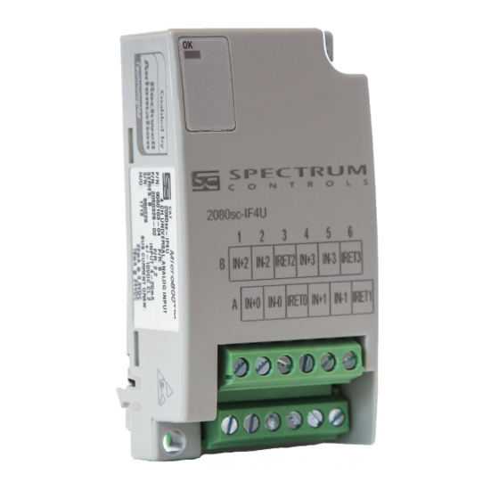
Micro800
4 Ch Universal Analog Input Module
(Catalog Number 2080sc-IF4U)
Contents
For More Information ................................................................................. 2
Environment and Enclosure ...................................................................... 2
Prevent Electrostatic Discharge ................................................................ 3
Parts List ................................................................................................... 4
Insert Module into Controller ..................................................................... 5
Wire the Module ........................................................................................ 6
Configuring the Module ............................................................................. 6
Module Input Data ..................................................................................... 9
Adding the IF4U to CCW ......................................................................... 11
Electrical Specifications .......................................................................... 12
Environmental Specifications .................................................................. 14
Hazardous Location Considerations ....................................................... 17
Environnements dangereux .................................................................... 18
Advertisement
Table of Contents

Subscribe to Our Youtube Channel
Related Manuals for Spectrum Controls Micro800 2080sc-IF4U


Summary of Contents for Spectrum Controls Micro800 2080sc-IF4U
-
Page 1: Table Of Contents
Install Guide ™ Micro800 4 Ch Universal Analog Input Module (Catalog Number 2080sc-IF4U) Contents For More Information ................. 2 Environment and Enclosure ..............2 Prevent Electrostatic Discharge ..............3 Parts List ....................4 Insert Module into Controller ..............5 Wire the Module ..................6 Configuring the Module ................ -
Page 2: For More Information
Micro800™ 4 Ch Universal Analog Input Module For More Information PLC sample projects and documentation are available on our website at www.spectrumcontrols.com Environment and Enclosure This equipment is intended for use in a Pollution Degree 2 industrial environment, in overvoltage Category applications defined... -
Page 3: Prevent Electrostatic Discharge
Micro800™ 4 Ch Universal Analog Input Module Prevent Electrostatic Discharge Electrostatic discharge damage integrated circuits or semiconductors if you touch bus connector pins. Follow these guidelines when you handle the module: • Touch a grounded object to discharge static potential. •... -
Page 4: Parts List
Micro800™ 4 Ch Universal Analog Input Module Parts List Your package contains one Micro800 Universal Analog Input Plug-in Module and one Quick Start guide. You can choose to wire the plug-in before inserting it onto the controller, or wire it once the module is secured in place. •... -
Page 5: Insert Module Into Controller
Micro800™ 4 Ch Universal Analog Input Module Insert Module into Controller Follow the instructions to insert and secure the plug-in module to the controller. 1. Position the plug-in module with the terminal block facing the front of the controller as shown. 2. -
Page 6: Wire The Module
Micro800™ 4 Ch Universal Analog Input Module Wire the Module Follow the wiring diagrams below to wire the module. 3-wire RTD Current Input 24 Vdc 2-wire RTD/Resistance 2 wire XMTR IN +2 IN -2 IRET2 IN +3 IN -3 IRET3 IN +2 IN -2 IRET2... - Page 7 Micro800™ 4 Ch Universal Analog Input Module 15 14 13 12 11 10 9 8 7 6 5 4 3 2 1 0 Bits 7 6 5 4 3 2 1 0 7 6 5 4 3 2 1 0 Type T TC 1 0 0 1 Type E TC...
- Page 8 Micro800™ 4 Ch Universal Analog Input Module Input Type Input Value Condition EU x1 EU x10 T Thermocouple 400.00 deg C High Range 4000 -270.00 deg C Low Range -2700 -270 R Thermocouple 1768.00 deg C High Range 17680 1768 0.00 deg C Low Range 100 Ohm Pt 0.385...
-
Page 9: Module Input Data
Micro800™ 4 Ch Universal Analog Input Module Module Input Data There are four input registers used to report data values for each of the four channels and one register to report CJC sensor temperature. Table 3 (Module Input Data) Channel 0 Input Data Channel 1 Input Data Channel 2 Input Data Channel 3 Input Data... - Page 10 Micro800™ 4 Ch Universal Analog Input Module Table 5 (Under/Over Range Status) O3 O2 O1 O0 U3 U2 U1 U0 Bit 0 is for channel 0 under range indication Bit 1 is for channel 1 under range indication Bit 2 is for channel 2 under range indication Bit 3 is for channel 3 under range indication Bit 4 is for channel 0 over range indication Bit 5 is for channel 1 over range indication...
-
Page 11: Adding The If4U To Ccw
Micro800™ 4 Ch Universal Analog Input Module Adding the IF4U to CCW The 2080sc-IF4U is configured for CCW (Connected Components Workbench) using the PLUGIN_READ and PLUGIN_WRITE instructions for generic plug-in modules. The configuration, input data, and status structures discussed in the sections above, are stored at different memory locations in the module. -
Page 12: Electrical Specifications
Micro800™ 4 Ch Universal Analog Input Module The following sample program, written in structured text, demonstrates how to configure the module in CCW. u800Slot := 1; (* Slot number for module. *) ConfigArray[1] := 0; (* Ch0 Config LSB *) ConfigArray[2] := 0;... - Page 13 Micro800™ 4 Ch Universal Analog Input Module Input Specifications CJC Sensor resolution ± 0.4 ºC maximum CJC Sensor accuracy ± 1.5 ºC maximum Voltage Accuracy System accuracy at 25 ºC (4 and 17 Hz filters) ± 40 µV maximum for ± 50 mV inputs ±...
-
Page 14: Environmental Specifications
Micro800™ 4 Ch Universal Analog Input Module Input Specifications 249 Ω ± 0.1%, 10 PPM/°C Current input impedance Input protection Voltage Mode ± 30 VDC continuous. Current Mode 28 mA continuous. Power source 3.3 VDC & 24 VDC from backplane, 30 mA max from each Electrical Isolation (continuous) 50 V RMS... - Page 15 Micro800™ 4 Ch Universal Analog Input Module Environmental Tests Industry Standards Test Level Limits (Enclosure) Class A, 30 MHz – 1 CSIPR 11; Group 1, Class A Radiated Emissions Rockwell Document QTP#X0327 IEC 61000-6-4:2007 Group 1, Class A (AC Mains), 150 Conducted Emissions kHz –...
- Page 16 Micro800™ 4 Ch Universal Analog Input Module Environmental Tests Industry Standards Test Level Limits IEC 61000-4-8 Magnetic Field Rockwell Document QTP#X0327 30 Arms/m (Performance Criteria A) IEC 61000-4-11 AC Mains Voltage Dips, Follow the 61000-4-11. Interruptions and Variations Rockwell Document QTP#X0327 IEC 61000-4-18 Oscillatory Waves Not Tested...
-
Page 17: Hazardous Location Considerations
Micro800™ 4 Ch Universal Analog Input Module Hazardous Location Considerations This equipment is suitable for use in Class I, Division 2, Groups A, B, C, D or non-hazardous locations only. The following WARNING statement applies to use in hazardous locations. EXPLOSION HAZARD •... -
Page 18: Environnements Dangereux
Micro800™ 4 Ch Universal Analog Input Module Environnements Dangereux Cet équipement est conçu pour être utilisé dans des environnements de Classe I, Division 2, Groupes A, B, C, D ou non dangereux. La mise en garde suivante s’applique à une utilisation dans des environnements dangereux. - Page 19 Micro800™ 4 Ch Universal Analog Input Module Publication 0100189-04 Rev. C...
- Page 20 1705 132nd Ave NE Bellevue, WA 98005 USA Tel: 425-746-9481 Fax: 425-641-9473 Email: spectrum@spectrumcontrols.com Web: www.spectrumcontrols.com Micro800 is a trademark of Rockwell Automation. Publication 2080sc-IF4U Install Guide – January 2020 © 2015-2020 Spectrum Controls, Inc. Printed in the USA. Publication 0100189-04 Rev. C...
Need help?
Do you have a question about the Micro800 2080sc-IF4U and is the answer not in the manual?
Questions and answers