
Subscribe to Our Youtube Channel
Related Manuals for Jeio tech Lab companion SI-300


Summary of Contents for Jeio tech Lab companion SI-300
- Page 1 sales@artisantg.com artisantg.com (217) 352-9330 | Click HERE Find the Lab Companion SI-300R at our website:...
- Page 2 OPERATING INSTRUCTION [SHAKING INCUBATOR] Model : SI-300/300R/600/600R Manual No: 00HAA0001134 ( Version : 5.0 ) This operating instruction describes the important subjects to maintain the product’s functions and to use it safely. Especially, be sure to read <Safety Precaution> carefully before you use this equipment.
-
Page 3: Introduction
■ Introduction Thank you for purchasing Jeio Tech’s product. This operating instruction forms a definition of warning marks according to the level of importance and danger in order to use the product safely and correctly and prevent the users from accidents or injuries. Hence, please use the product in accordance with the instructions. - Page 4 3. It forbids reorganization of Inside of the product or adds. 4. Do not assemble, repair, modify by entities than Jeio Tech’s representatives. It becomes the cause of electric shocks, fires and improper operations.
-
Page 5: Confirmation Of Transport
1. Any damage that is occurred during the transport is responsible to the delivery service company. 2. Except for all damage from the transport, we Jeio Tech will service or refund. 3. If Jeio Tech or our authorized dealers do not deliver the unit, Jeio Tech disclaims all the responsibility for the damage. - Page 6 ■ Components of SI-300/300R/600/600R After unpacking the unit, check the following components. In addition, check the features and electric condition. Components Components Power Cord unit Fuse Operating instruction Software CD for Spacer communication Cable for communication Page 5...
-
Page 7: Table Of Contents
Table of Contents ◆ Introduction ◆ Confirmation of transport OPERATING MANUAL 1. Warning for safe operation 2. Caution for safe operation 3. Safety alert definitions 4. System composition of SI-300R,600R 5. Introduction 6. Controller instruction 7. How to change the orbital motion and reciprocation motion 8. -
Page 8: Warning For Safe Operation
1. Warning for safe operation Warning means that failure to follow this safety statement could result in serious personal injury, or death. 1. Please check the voltage, phase and capacity of power supply and connect properly. ☞ Abnormal connection causes fire or electronic shock. ☞... - Page 9 11. Do not use or keep the inflammables near by the product. ☞ Inflammable gas or dust may cause fire. ☞ It may cause fire or explosion. ☞ Do not operate the product in a dangerous article area. 12. Never put inflammables and explosives in the product. ☞...
-
Page 10: Caution For Safe Operation
2. Caution for safe operation Warning means that failure to follow this safety statement could result in serious personal injury, or death. 1. Do not pour water or put liquid on the top of the product when cleaning. ☞ It causes abnormal operation or trouble. ☞... -
Page 11: Safety Alert Definitions
3. Safety alert definitions The safety alerts, attaching on the product, provide information of danger and safety about it. All users must read this operating instruction carefully to operate the product properly. The safety alerts should be attached in the same place below until disusing the product. -
Page 12: System Composition Of Si-300R,600R
In the event of the CPU failing, the logic controlling the safety features will often be compromised. Jeio Tech has separated these two important elements and now has an independent safety system running alongside the performance controller. - Page 13 Uniform temperature control ■ If the cover is opened, fan and heater will be stopped immediately to keep away meeting inner air with outer air. ■ We use a cross type fan to make good uniformity. Prevention against inner air leakage ■...
-
Page 14: Introduction
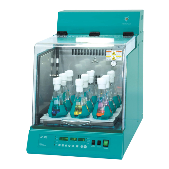
5. Introduction ※ SI-300/600 ※ SI-300R/600R ※ Back side (1) Cover Easy to observe the sample through Acrylid. (2) Over Temp. limit This the safety device which is independent of the circuit. The Heater reaches over the setting value, the controller shutdown of the main power Completely. - Page 15 (5) Compressor Cover The cover for the refrigeration System A/S. (6) Foot The foot for protected the unit from the dust.. (7) Shaking table The shaking table relates to the shaking system. This can be installed the Universal Platform, Spring wire wrack and other accessories. (8) Main switch Turn power on / off switch to unit (9) Shaker I/O Switch...
- Page 16 And it blocks off the power to be authorized with a power switch, and Off gets a power switch done and all blocks off 2 phase of the power supplied with to an each part of appliances, and configuration does the safe state that only a Ground part is connected.
-
Page 17: Controller Instruction
6. Controller instruction Planning for the shaking incubator This controller is divided into the Temp LED and shaking LED Once setting the controller, the operator can use the Temp & shaking function simultaneously. Know well the operator to perform functions like temp, shaking, programmed all on the controller in right process. - Page 18 4. Shaker LED Shake LED Illuminates When setting the time. Flashes during the timer mode. F/Ward Illuminates when settting clockwise timer. Flashes during timer mode anti clockwise mode. B/Ward Illuminates when setting the anti clockwise timer. Flashes during the timer or clockwise timer Pause LED Illuminates when setting the pause timer.
- Page 19 6. Entering button for the setting value Temp Button Setlects for the temp Timer Button Selects for the timer. Up Button Increases the set value. Down Button Decreases the set value. Enter Button After setting the value, store the set value using of Enter button.
- Page 20 The unit Operation Before using the unit, Make sure the shaking direction to p rotect the unit from the dust P osition the appropriate accessaries on the shaking table and toghten securely. If using the temp function, the unit should be operated 5minutes before.After maintaining the temp uniformity, install the vessels and accessarries on the shaker table.
- Page 21 Additional Function of Temp Button Restoration the Set value This function can restore Three frequently used temparatrue Each SV1,SV2,SV3 mode. Press the TEMP button,SV display will be activated. Press the Temp button again,SV1 will appear on the PV display. ① Select the desired temp using of Up button and Down button.
- Page 22 2. The moethod of using set temp on SV2 In case of the main screen, Press the TEMP button twice. ① Press Enter button once to display SV2 on the PV display ② After checking the SV 2 temp, Press Enter button. ③...
- Page 23 BIAS Function This function is for revising the temp diffrence caused by the temp sensor or other sources. Press Temp button for six times to move the bias function. Displayed the revised value on the PV display and Bias on the SV display.
- Page 24 Timer set function On Timer Set In case of the main screen, Press the Timer button once. Displayed Timer on the PV display and Time on the SV display. ① Press bbutton Down button to set the desired time. Press Enter button to finish. ②...
- Page 25 Auto Run Function Press Timer button three times, Auto function displayed ① This function is for compensation form power interruption. When the power is out, the unit starts operation automatically after power is on.. ② Use Up button Dwon button,Select “ YES” or “ NO” . ③...
- Page 26 Program Control Function of Timer Button 9- steps Prgramed Control serve to operate each 9deffrent temperatrue and time (99hours 59minutes, max). Possible to repeate the operation from one to 200 cycles. Press Timer Button 5times, the Prgrammed Control Function is displayed ①...
- Page 27 ⑤ The Prg2.will appear on the display. Use Up button and Dwon button to select the desired segment. Press Enter button to finish the set.From selection of ③ ~ ⑤, 9step prgram will be set. In Prg2, Time 2 and Temp 2 be set and In Prg3, Time 3 and Temp 3 be set.
- Page 28 Auto Tune function Auto Tunning is for more accurate and fast temp control. After Tuning, PID value will be stored automatically. ① Press the Temp button and select the desired temp. ② Press the A/T Button for a second, Auto Tune is displayed with illuminating A/T LED.
- Page 29 Shaking Control Function rpm Set RPM indicates the rotation of motor. RPM is the same as 1cycle of the shaking table. Please check the proper rotational. Avaiilable rotation is 10~300RPM. Able to set the value when the unit stops or rotate without the timer mode.
- Page 30 Timer set Function The operator can set time/clock/anti clock mode whatever wants or select the one mode. Whole time set(HHH) : Set the hour in timer mode. Press SHAKE/SET button twice,“run.H”appeared on the PV display. The earlier time appeared on the SV display. Set the time with Up button and Down button.
- Page 31 Forward time(MM:SS) Set Press SHAKE/SET button four times,” For.S” will be appeared on PV display.The previous time will be displayed on the SV. Use Up button and Dwon button To set the time then, Press Enter button. The F/WARD LED illuminates (Maximum Input time: 10seconds ~ 59minutes 59seconds) Backward time(MM:SS) SET...
- Page 32 The example of Timer function When not using the Timer function (All Shaker LED are out) After input the desired rpm, Press the START/STOP button. The shaker operates forward. If the user stops the shaker, press the START/STOP button or The Shaker I/O button.
- Page 33 The whole time Set + Forward and Backward Action (SHAKE LED illumination + Forward LED and Backward LED illumination) 1. Select the hour or minutes in the whole time set, Press Enter button to iluminate Shake LED. 2. After setting the forward time, Press Enter button to iluuminate F/WARD LED.
- Page 34 The wholetime set + Forward + PAUSE or Backward + PAUSE (SHAKE LED illuminnation + Forward LED and Backward LED illumination + PAUSE LED illumination) 1. Select the hour or minutes in the whole time set, Press b utton to iluminate Shake LED. 2.
- Page 35 Whole time set + Forward + PAUSE + Backward operation (SHAKELED/Forward LED/Backward LED/PAUSELED illumination) 1. After seting the whole time, Press Enter button to illuinate SHAKE LED. 2. After setting the backward and forward, Press Enter button to illuminate F/WARD LED and B/WARD LED. 3.
- Page 36 SHAKER Movement display Function This Function is for displaying the presnt shaking table. When maintaing rpm, the display starts a circular movement. Forward(accelation) Forward(deceleration) Backward(accelation) Backward(deceleration) Page 35...
- Page 37 Shaker/Incubator Control Choices In a case of the unit stops, the previous rpm, Temp,Timer funcion can be used with slecting shaking and temp at the same time Press the START/SET button for seven times.”Snch”will appeared on PV display and “on the SV.
- Page 38 Example of using Shaker/Incubator at once ① Select “Yes”on SV display ② Set the desired temp with pressing the Temp button. (Refrence Page 22) Select the desired rpm with Shake/Set button(Reference Page 22) ③ Press SHAKE/SET button,the shaking table and incubator operates together.
-
Page 39: How To Change The Orbital Motion And Reciprocation Motion
7. How to change the orbital motion and reciprocating motion motion Reciprocating Orbital ① Carefully remove the Shaking Table(Part 1) after loosing 4pieces of 5mm Wrench Bolt. ② Remove 4pieces of the Spacer(SI-300/300R : M5X23, SI-600/600R : M5X28) fixed on the Vibration Frame. -
Page 40: Accessories
8. Accessaries 1. Flask Clamp installed Capacities and Drawings Model: SI-300/300R 50 ㎖ Flask + Flask Clamp Location of fixed holes Maximum fixed numbers: 28 EA 100 ㎖ Flask + Flask Clamp Location of fixed holes Maximum fixed numbers: 24 EA Page 39... - Page 41 Model : SI-300/300R 250 ㎖ Flask + Flask Clamp Location of fixed holes Maximum fixed numbers: 13 EA 500 ㎖ Flask + Flask Clamp Location of fixed holes Maximum fixed numbers: 9 EA Page 40...
- Page 42 Model : SI-300/300R 1,000 ㎖ Flask + Flask Clamp Location of fixed holes Maximum fixed numbers: 4 EA 2,000 ㎖ Flask + Flask Clamp Location of fixed holes Maximum fixed numbers: 2 EA Page 41...
- Page 43 Model : SI-600/600R 50 ㎖ Flask + Flask Clamp Location of fixed holes Maximum fixed numbers: 45 EA 100 ㎖ Flask + Flask Clamp Location of fixed holes Maximum fixed numbers: 36 EA Page 42...
- Page 44 Model : SI-600/600R 250 ㎖ Flask + Flask Clamp Location of fixed holes Maximum fixed numbers: 18 EA 500 ㎖ Flask + Flask Clamp Location of fixed holes Maximum fixed numbers: 13 EA Page 43...
- Page 45 Model : SI-600/600R 1,000 ㎖ Flask + Flask Clamp Location of fixed holes Maximum fixed numbers: 7 EA 2,000 ㎖ Flask + Flask Clamp Location of fixed holes Maximum fixed numbers: 5 EA Page 44...
- Page 46 2. Spring Wire Rack Easy to fix the vessels or Test tube through the Spring Wire Wrack. SI-300/300R Flask Max Capacities (EA) Flask Max Capacities (EA) 50 ㎖ 16 EA 500 ㎖ 4 EA 100 ㎖ 9 EA 1000 ㎖ 2 EA 250 ㎖...
-
Page 47: Cause Of Malfunction And Its Repairs
9. Causes of malfunction and its repairs 1. When the unit stops running Troubleshooting Check point and Settlement ① Check the main power. ② Check the Fuse.. ③ Check the RUN Led display is off. When the unit stops running ④... - Page 48 (2) Electricity Phenomenon Check point Settlement Even if Power Switch Stops a driving immediately and contacts Leak. ON, OFF promptly.. a reseller A power plug being Leaves Power Switch OFF, and please put a Even if Power Switch Disconnected from an outlet. power plug in an outlet.
- Page 49 (3) Shaker Phenomenon Check point Settlement shaker stops Check Sync Parameter is no. Select Sync Parameter is “yes”or Press operation by START/STOP (Reference Page 36 ~ 37) Shaker I/O Switch to operate. When the shaker speed down, Check the unit location and Provide the main volt.
-
Page 50: Inspection Cycle
10. Inspection Cycle Classification Week Month Year Remark ○ Clean Condition Connection ○ Condition ○ Shaker Noise Air Filter ○ Cleaning ○ Vibration ① Be sure to maintain the unit frequently by a person authorized. ② Make no attempt to service or repair the unit when the power is on. Be danger of ③... -
Page 51: Maintenance And Cleaning
11. Maintenance and Cleaning 1. Maintenance If the unit will not be used for a long time, maintain as follows. Please turn off the power switch Disconnect the power cord. Clean the inside and outside of the unit. Maintain the unit with packing. 2. -
Page 52: Specification
12. Specification MODEL SI-300 SI-300R SI-600 SI-600R Chamber volume Temperature 5℃ to 40℃, Permissible environmental condition Maximum relative humidity 80%, Altitude up to 2,000m Digital PID Auto Tuning, 9step programmed control 200cycle Controller Amb.+5℃~60℃ +15℃~60℃ Amb.+5℃~60℃ +15℃~60℃ Range ±0.1℃ at 38℃ (at room temp. 25℃) Accuracy Temperatur ±1.0℃... -
Page 53: Warranty Standard
13. Warranty standard 1. Service under Warranty period If trouble occurs during product use, User can get free service for one year from the date of purchase. 2. Exceptional cases even during under warranty period User can not be created by warranty in case of as below. ①... -
Page 54: How To Waste
14. How to waste To waste main parts Configuration Gross External dimension(mm) Model How to waste Parts Weight(kg) (WⅹDⅹH) Main body SI-300 74kg 420ⅹ740ⅹ622 Main body SI-300R 85kg 420ⅹ740ⅹ622 Contact a company which dealing with waste parts. Main body SI-600 91kg 540ⅹ842ⅹ622 Main body... -
Page 55: Warranty
15. Warranty General matter ① The term of guarantee about responsibility on manufacture is one year from purchase work under. Purchase date Serial number A trouble part and trouble state Equipments use environment Guarantee exception Charge within the term of guarantee if as follows. A use mistake of a user A mistake of treatment of a user and custody Unfair change of usage, remodeling of a machine and acceptance... -
Page 56: Setting Monitoring Program
16. Setting Monitoring Program 1. Insert an installation CD, and then the software starts installation automatically. (In case of no automatic running, run “SETUP.exe” file in CD.) 2. Click Next” button to choose destination of installation. (Default folder recommended) 3. Click “ Install” to start installation. 4. -
Page 57: Operating Monitoring Program
17. Operating Monitoring Program 1) Connection for communication Click Comm → Connect and your PC and equipment will be connected to RS-232 communication. (In case of no connection, click Comm → Port and try other ports.) “ On Line” displays on the bottom of the software once communication is connected successfully. - Page 58 The picture above is a monitoring window after choosing Status and Parameter in View menu. User can monitor operating process through three divided windows. (Graph, Parameter, Status) 2.2.1. Graph displays; Actual temperatures (Red line) and set temperatures (Blue line) on the top of the graph windows.
- Page 59 1. Operating represents the unit is running. - If blue line is high, the unit is on (operating). If blue line is low, the unit is off. 2. Auto Tune displays whether the unit performs Auto Tuning or not. 3. Program displays whether the unit is in programmable mode or not. 4.
- Page 60 ○ 8 ○ 9 Scroll icon - To scroll graph. 1 0 ○ 1 1 Auto Trace On/Off ○ - If you want to fix and monitor the end point of graph on the center of windows, Click Auto Trace. 1 2 ○...
- Page 61 ※ Printing operation ① Print range - All: Print total pages. - Print the screen: Print the current screen. (Graph, Status, Parameter Frame will be printed when they are on the main screen. If not, they will not be printed.) - Current page: Print a page on the current main screen.
- Page 62 ※ Preview and print When print at equal intervals is checked, PV and SV are printed in a regular interval like the preview above. If user wants to check a certain point, move curser to the point and click. Green line with PV and SV will be printed on the copies.
- Page 63 ※ Display All the functions of display window are same as those of main display panel. If communication via RS-232 between PC and main body is connected, user can control main body with your PC at a distance. ※ Pattern Program The following window will be open when you click PRG icon or Pattern ->...
- Page 64 Pic 3. SV Pattern after clicking a certain point of window. you want to edit the selected point, Drag & Drop the selected step (blue color). It is very convenient to use short-keys when you want to change temperature and time because temperature can be adjusted by 1 degree, and time can be adjusted by one minute.
- Page 65 ④ Pattern save - Save programmed pattern. - File extension is PIT. - Choose a folder and write a file name. Then, click save button. ⑤ Pattern open - Choose a pattern file and click open. ⑥ Start - Click the START icon to operate the equipment after pattern is set. Note: i) If the main body is under abnormal condition such as Door Open, Over Temp.
- Page 66 - Maximum operating time is 99 hours. - If you program total working time over 99 hours, the unit does not operate in a Program Mode. Especially be cautious when you program a pattern repetition. - Please, be aware of specification about program time and temperature. - If you program the pattern that exceeds equipment capacity, the unit can not work properly.
- Page 67 Page 66...
- Page 68 Page 67...
Need help?
Do you have a question about the Lab companion SI-300 and is the answer not in the manual?
Questions and answers