
Related Manuals for Jeio tech ISF-7100


Summary of Contents for Jeio tech ISF-7100
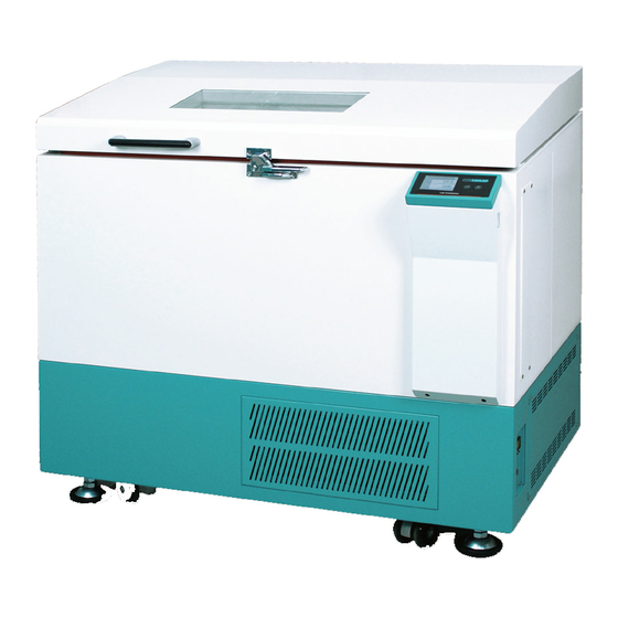
- Page 1 Operating Manual Shaking Incubator Model : ISF-7100, ISF-7200, ISF-7100R, ISF-7200R Menual no. : XXXXXXXXXXX...
- Page 2 Manual and take all necessary safety precautions while using this product. Failure to follow these guidelines could result in potentially irreparable bodily harm and/or property damage. Thank you for purchasing Jeio Tech’s products. We are doing best for customer’s satisfaction.
- Page 3 Visit our Web site at www.jeiotech.com to view a copy of our certificate. Disclaimer Jeio Tech Co., Ltd. is committed to a continuing program of product development and improvement, and reserves the right to change information, such as specifications, appearance, and dimensions, described in this document without notice.
-
Page 4: Table Of Contents
3.4 Installation ................................14 3.4.1 Caution for Installation ..........................14 3.4.2 Adjusting the Horizontality ........................... 15 3.5 Attaching Condensate Drain..........................16 3.6 Attaching/Detaching External Refrigeration (ISF-7100, ISF-7200 Only) ........16 3.7 Connecting Power ..............................18 4 Operation ....................................19 4.1 Controller .................................. 19... - Page 5 4.3 General Settings ..............................27 4.4 System Settings ..............................28 4.4.1 Control Deviation Limit ..........................28 4.4.2 External Start/Stop Key ..........................28 4.4.3 Calibration ................................29 4.4.4 Auto Tuning ................................ 31 4.4.5 Operating Parameters ..........................31 4.4.6 Reset ..................................31 4.5 Safety Tool ................................
- Page 6 9.3 Circuit Diagrams ..............................54 9.3.1 Incubator circuit diagram ..........................54 9.3.2 Shaker circuit diagram ..........................55 9.3.3 External Refrigeration connection system (ISF-7100/ISF-7200) ..........56 9.3.4 Internal Refrigeration system (ISF-7100R/ISF-7200R) ..............56 9.4 Disposing of products ............................57 9.5 Warranty ..................................57...
-
Page 7: Safety
1 Safety 1.1 How to use manual This manual is intended for individuals requiring information about the use of product. Use this manual as a guide and reference for installing, operating, and maintaining your Jeio Tech product. The purpose is to assist you in applying efficient, proven techniques that enhance equipment productivity This manual covers only light corrective maintenance. -
Page 8: Exemption For Responsibility
1.3 Exemption for responsibility (1) The claim which is out of the quality guaranteed by the manufacturer is out of manufacturer’s responsibility. (2) The damage which is from unexpected fault or damage of user by Acts of God is out of Manufacturer’s responsibility 1.4 Caution statement Indicates a hazardous situation which, if not avoided,... -
Page 9: Caution Statement For Safe Use
Power supply must be properly grounded. Abnormal grounded connection causes serious damage. Grounded connection must not be on the water pipe and gas pipe. Put off the power plug if some sounds and burning smell, smokes are happened. And request the service Stop the product operation and request service. - Page 10 Do not let the product take any strong shock or vibration. It causes abnormal operation or trouble. It may deteriorate the ability of the product and not obtain correct results. Do not install the stirrer neat machinery generating high frequency noise. Please avoid installed from high frequency- welding machine, sewing machine, and mass SCR controller Do not sprinkle insecticide or flammable spray on the product.
-
Page 11: Functional Description
2 Functional Description 2.1 Introductions The cultivation environment such as temperature, pH, oxygen concentration, nutrition supply have a significant impact on cell cultures of animals and plants or proliferation of microorganisms. This incubated shaker is to provide a suitable environment for the cultivation through controlling constant temperature and shaking speed. -
Page 12: Advanced Convenience
2.2.2 Advanced Convenience (1) User friendly interface according to Touch LCD. Eidetic unit operation check and easy to control. (2) Timer and operation time check of shaking performance is available. Setting and checking the value is available up to 999 hours and 59 minutes. (3) Large window with LED lamp on the door offers the convenience to monitor the samples in the chamber without opening the door in the dark place. -
Page 13: Structure
Structure (1) LED Lamp Long life span and energy efficient LED lamp offers bright observation of samples. (2) Door Switch There is a door limit switch between the door and the appliances mainframe’s upper parts. If the door is opened, Shaking, Blower and Heater operation automatically stops. After 3 minutes at this status, warning sound alarms users to close the door. - Page 14 (4) Door Latch Door latch is additionally equipped to advance the air tightness of the inner chamber. Close the door and turn door latch to the right. (5) Control Panel Main control part. Improved immediacy and convenience by touch LCD. User can set-up temperature and shaking control with this controller.
- Page 15 (14) Drain Port and Valve for Spilled Liquids In case of the liquid leakage caused by spilled reagent or cracked flask inside of the chamber, the liquid is designed to be drained out through the drain of the chamber bottom which is connected to the port on the product’s side.
- Page 16 (18) External Refrigeration Port (ISF-7100/ISF7200 only) Even if the model such as ISF-7100 which has no refrigerator, It can lower the temperature in the chamber by receiving refrigerant from the external refrigerant device such as chiller. The In/out ports (refer to the figure) are located on the back and bottom side of the device.
-
Page 17: Installation
(2) Remove the outer container. (3) Before use, inspect the product carefully for any damage that may have occurred during shipping. (4) Report any damage to your local Jeio Tech office or the distributor. 3.2 Component (1) After unpacking, check the components. -
Page 18: Preparation Before Installation
Power Cord Operating Manual 3.3 Preparation before installation 3.3.1 Space requirements It is essential that the product to be situated in an area where there is sufficient space for the product. Below figures show the minimum space requirements needed to properly operate and maintain the product. -
Page 19: Environmental Setting
3.3.2 Environmental Setting The unit can be operated properly under the following environmental conditions for a long time running without any problem. No direct sunlight on the product Ambient temperature: 5℃ ~ 40℃ (41℉~104℉) Relative humidity not to exceed 80% Altitude not to exceed 2000m (6,562 feet) Connect the product to earth grounded terminals only. -
Page 20: Installation
3.4 Installation 3.4.1 Caution for Installation (1) The device is recommended to use under the room temperature and humidity (30°C, 80%RH) do not install it near the Heat devices like a Heater. (2) Have enough space for door opening. (refer to 3.3.1) (3) Please install it on the sturdy surface laboratory and do not throw down or gives a big shock. -
Page 21: Adjusting The Horizontality
3.4.2 Adjusting the Horizontality (1) Put the unit the desired place. (2) Using the spanner, adjust the height of caster. Turn the ① nuts to the right, the height is increased. The caster must be lifted up at least 5mm from the bottom. (3) Put the level on the top of the unit and check the horizontality. -
Page 22: Attaching Condensate Drain
Many laboratories are built with central chilling systems. With this in mind Jeio Tech has developed the ISF-7100/7200 so that it can be connected to external refrigeration systems. To connect the unit to an external refrigeration source use Ø 8mm OD hard-walled tubing, such as nylon or polyethylene. - Page 23 (2) Removing from fitting Grab the tubing tightly and push towards the incubated shaker as you firmly push the collet release button with two fingers. Continue to push the collect release button, and pull the tubing out of the fitting. 17...
-
Page 24: Connecting Power
3.7 Connecting Power JEIOTECH’s Shaking Incubators use a single-phase current. Use a suitable plug as the picture bellow by Identification label. Voltage is the 10% of applied voltage. 220/230VAC 110/120VAC • Connect the power with checking the voltage, Phase, Capacity. •... -
Page 25: Operation
4 Operation 4.1 Controller The controller is consist of the touch screen, LED, membrane. Once the power is supplied, below display is appeared. Main Display Main Display for the operation. General Setting General setting. Parameter setting is available. For change the parameter, System Setting acknowledge the manual. -
Page 26: How To Use The Controller
4.2 How to use the controller Setting is available on the main display. Set RPM Display the setting RPM. Touch the screen, set the RPM. Set Temperature Display the setting temperature. Touch the screen, set the temperature. Set Timer Display the shaking time. Touch the screen, set the timer. In the case of no timer is set, the operating time is displayed. - Page 27 Silent In the case of attention on the unit is required, the unit generates the alarm. Touch the silent, the unit stops the alarm. Once the problem is not eliminated, the unit generates alarm again. Status Bar The unit stops the platform on the same position. This display indicates that the platform is on the right position.
-
Page 28: Temperature Control
4.2.1 Temperature control (1) Start temperature control Touch the set temperature button on the main display. Setting display is appeared. Set the temperature with touch pad and touch the start button. The temperature control starts. SV and PV is displayed on the main display with green color. -
Page 29: Shaking Timer
Move out from the setting mode with ESC button. In the case of no touch for 10 seconds, the display changed to the main automatically. Check the PV, RPM on the setting display is available. (right upper side) ... -
Page 30: Alarm And Stop By Force
Once the setting time is changed during the timer operating, original set time is changed. The accumulated time is applied to the new time setting and the remaining time is calculated and displayed. If you want whole new time setting, off the timer and set the timer again. ... - Page 31 Temp. Deviation The temperature difference between setting temperature and present temperature is more than the range of the permission. The unit check it once the present value reached to setting value. Once the gap is over the permission range, the alarm is generated. RPM Deviation The rpm difference between setting rpm and present rpm is more than the range of the permission.
- Page 32 Get back to the work after stopping the control. (Door open, Stop operating) Defrost is under progress (Temperature control) Once the Deviation initialized, the unit check the present value. If the temperature not reaches to the SV for 4 hours and the rpm not reaches to the SV for 10 minutes, Deviation check is started. ...
-
Page 33: Defrost (Refrigerated Model, Isf-7100R, Isf-7200R Only)
4.2.5 Defrost (Refrigerated model, ISF-7100R, ISF-7200R Only) The refrigerated model activates automatic defrost when the setting temperature is saved under the certain temperature. The defrost operation can raise the temperature of the chamber. Also the defrost mark will blink on display to indicate defrost progress. ... -
Page 34: System Settings
System Settings Set the main variable that affects on the unit. Please read the manual carefully before setting the system. Touch the System setting button on the home display, below clauses are arranged. Control Deviation Set the deviation limit range. Temperature setting and rpm setting are Limit available. - Page 35 Shaker and incubator are both available for the external membrane button. Once one of the shaker/incubator is on the generating and touch the button, the stopped part is operated. Touch the button again, both of mode are stopped. 4.4.3 Calibration The temperature sensor and rpm reached to the user’s reference measure value, accurate experiment circumstance can be made.
- Page 36 Once the door is opened or the temperature is out of range, the temperature control is stopped. The calibration is operating on various points so it limits the calibrating that is our logic. The result of the calibration is on the uncalibrated and calibrated. Uncalibrated means the value from the unit and the calibrated means the temp that calibrated.
- Page 37 4.4.4 Auto Tuning Update the parameter of PID temperature control. Optimum temperature for the main using temperature is available. The unit is set to use the temperature on proper range. Once the temperature is not actual on the main points during the actual use on the field, operating auto tuning will tune the temperature parameter and make the unit operates the temperature on the actual temperature.
-
Page 38: Safety Tool
4.5 Safety Tool 4.5.1 Over Temp. Limiter This model has the over temp limit and temp sensor in the main controller. Over temp limit is located on the right down side of the unit. Set the over temp limit over 15% than normal use temperature by a flat head screwdriver. -
Page 39: Maintenance
Power ● Connection between machine and power ● Power code ● Exterior cleanliness ● Drain connection Outside refrigeration system connection ● (ISF-7100/ISF-7200) Incubator Set temperature and actual temperature ● difference ● Auto Tuning Temperature setting ● Temperature correction ● Actual temp. / Display temp. correction (ISF-7100R/ISF-7200R) ●... -
Page 40: Cleaning
5.2 Cleaning (1) After disconnect the power cord, clean the machine with soft and dried towel. Regarding the un-removable point, clean the polluted area only by towel with alcohol solvent (methanol, ethanol) which has low boiling point. (2) Do not use Acid solution, sharp one, soapy water, detergent and hot water. It makes the machine discolored. -
Page 41: Air Filter Cleaning (Isf-7100R/Isf-7200R)
5.3 Air filter cleaning (ISF-7100R/ISF-7200R) • When air filter clean, please be careful to avoid fold the condenser pin. It is possible to decrease refrigeration effect. Step 1: Put power switch and turn the machine off. Step 2: Loosen the bolt that located in edge of condenser cover Step 3: Disassemble condenser cover Step 4: Disassemble air filter which is combined with condenser cover. -
Page 42: Fuse Replacement
There is extra fuse 2pcs in socket case inside. If you need additional fuse, ask it to sales team or seller. Current Model Voltage Fuse (A) Fust Cat. No. consumption(A) 230VAC, 50/60Hz 00CDE0005543 ISF-7100 120VAC, 60Hz 00CDE0005541 230VAC, 50/60Hz 00CDE0005543 ISF-7200 120VAC, 60Hz 00CDE0005541 230VAC, 60Hz... - Page 43 Caution to Electrical shock. Before replace the fuse, turn the machine off and check the power connection again. If the power is connected, serious injury or death can be occurred. Step 1: Press power switch and Power off Step 2: Connect (-) screw driver to fuse holder Spin the fuse holder counterclock wise 50 ˚...
-
Page 44: Troubleshooting
6 Troubleshooting 6.1 Stop during the operating Display Description Solution Message Check the set on the analog over temperature regulator and the operating. Temperature Analog over temperature regulator is Restart after temperature is inside of the Limit active. range. Vibration is generating and the Load normal shaking is not available. -
Page 45: Another Problem And Solution
6.2 Another problem and solution Trouble Probable Cause & Solution ① Check the power plug connection to the socket ② Check if the circuit breaker is operated The equipment is not ③ When the fuse is short circuited, replace new one as enclosed. ④... - Page 46 speed is slow down, check the sample location and relocate the samples harmoniously ③ In case of overloading, control the sample weight according to 9.1(Max load per speed). ④ Check door switch if shaking is not operated after shaking start button press.
-
Page 47: Accessories
7 Accessories 7.1 Mountable maximum quantity 7.1.1 Universal Platform + Flask Clamp Model ISF7000 series Flask Clamp 50ml 100ml 250/300ml 500ml 1,000ml 2,000ml 2,800ml 4,000ml 6,000ml 7.1.2 Universal Platform + Plastic Flask Clamp Model ISF-7000 series Flask Clamp 50ml 100/125ml 200ml 250ml 300ml... -
Page 48: Universal Platform + Funnel Clamp
7.1.3 Universal Platform + Funnel Clamp Model ISF7000 series Funnel Clamp 250ml 500ml 1,000ml 2,000ml 7.1.4 Universal Platform + Microplate Holder Model ISF7000 series Type Single Tower Flat A(large) Flat B(small) 7.1.5 Universal Platform + Test Tube Rack Model ISF7000 series Type 0°... -
Page 49: Spring Wire Rack + Flask
7.1.6 Spring Wire Rack + Flask Platform ISF7000 series Flask 50ml 100/125ml 250/300ml 500ml 1,000ml 2,000ml 2,800ml ※ About the right position for mounting maximum quantity of Accessories, please visit Jeio Tech website or contact our office and distributor. 43... -
Page 50: S/W
8.0 S/W 8.1 Monitoring Program installation (1) Put the installation CD on the CD-ROM drive then the program is operated automatically. Click the “Next” button go to the License Agreement. (2) Check the details and click the “I agree”. 44... - Page 51 (3) Click the “Install” and install the program. (4) Once the program is installed, below window is up and JeioTechSoft icon is generated on the background. Check the Run JeioTechSoft 2.0.0.5 or double click the icon then the program starts. 45...
-
Page 52: Communication Protocol
Communication Reference : http://www.modbus.org/docs/Modbus_Application_Protocol_V1_1b3.pdf 8.2.1 Physical Layer Communication port : RS-232C /USB 8.2.2 Model System number ITEM System Number System Model Number 1601H Shaking incubator ISF-7100 1602H Shaking incubator ISF-7100R Incubated Shaker 1603H Shaking incubator ISF-7200 1604H Shaking incubator ISF-7200R... -
Page 53: Modbus Protocol Address Definition
8.2.3 Modbus Protocol Address Definition data length modbus address command data description function code word byte BEEP_SYS_BOOT(Commu 0x0001 nication Test) Beep BEEP_KEY(Communication 0x0002 Test) MOD_SYS_NA Model name MOD_SYS_VE Firmware Version MOD_SYS_PA system parameter MOD_SYS_SO W/S, R/I system sound MOD_SYS_LA W/S, R/I 1 ~ 3 lamp bright MOD_SYS_LA... -
Page 54: Modbus Protocol Description
8.2.4 Modbus Protocol Description Command Description Modbus function code System boot beep Write Beep Beep generating Data data System key beep Modbus Return the unit name MOD_SYS_NAM function code Upper Lower Refer to System Return data address Model num number Modbus Return the firmware MOD_SYS_VER... - Page 55 addres uppe lower auto run flag modbus function auto run code data auto run data modbus function 0 ~ 3 code return addres data temp devi temperature MOD_TEMP_DEVI deviation modbus function temp devi min ~ value code value modbus function code return addres...
- Page 56 shake incubato value modbus function 0 ~ 3 code return data addre temp MOD_SET_TEMP incubator set temp modbus function high temp ~ low 0 ~ 3 value code temp value modbus function code return addre data set rpm MOD_SET_RPM shaker set rpm modbus function value rpm min ~ max...
- Page 57 dumm dumm dumm temp auto usb_m sk over cur delay tune 무시할 report 것. slave temp silent load sk load temp devi hold hold devi warn system 4byt indicate auto sens door door mute refrig warn warn open error silent incubat connec lamp...
-
Page 58: Appendix
9.0 Appendix 9.1 Technical Specifications MODEL ISF-7100 ISF-7100R ISF-7200 ISF-7200R Amb.-20 (Min. Amb.-20 (Min. Range Amb.+5~80℃ Amb.+5~80℃ +4)~80℃ +4)~80℃ Accuracy ±0.1℃ in flask at 37℃ Temperature Uniformity ±0.5℃ in flask at 37℃ Refrigerator (Hp) 1/6Hp 1/6Hp Pt 100Ω Sensor Type... -
Page 59: How To Use High/Low Temp. Limit
9.2 How to use High/Low Temp. Limit As the standard (the temperature of NTC sensor), Circuit switch is off when out of limit of High/Low temperature. Basic display : showing allowed High temp (H), allowed Low temp (L). H : 112 ℃ L : 0 ℃... -
Page 60: Circuit Diagrams
9.3 Circuit Diagrams 9.3.1 Incubator circuit diagram 54... -
Page 61: Shaker Circuit Diagram
9.3.2 Shaker circuit diagram 55... -
Page 62: External Refrigeration Connection System (Isf-7100/Isf-7200)
9.3.3 External Refrigeration connection system (ISF-7100/ISF-7200) 9.3.4 Internal Refrigeration system (ISF-7100R/ISF-7200R) 56... -
Page 63: Disposing Of Products
2. Please contact your local governing body for regulations regarding disposal of electrical, electronic, metal (brass, aluminum, steel and stainless steel), refrigeration and rubber components. Jeio Tech recommends the user find a local scavenger or laboratory equipment recycler to properly dispose of the unit and its components. -
Page 64: Warranty Exception
9.5.2 Warranty exception Customer can’t get free warranty service in case of as below. If the product is broken due to the user’s fault. • • If the product is broken due to improper operation or storage. • If the product is broken due to improper modify or repairing. •... - Page 65 The Americas (U.S.A. Branch) 19 Alexander Road, Unit #7. Billerica, MA 01821-5094, U.S.A. Tel: +1 781 376 0700 E-mail: info@jeiotech.com FAX: +1 781 376 0704 Europe (U.K. Branch) Unit 3, Tower Industrial Park, Chalgrove, Oxfordshire, OX44 7XZ, United Kingdom Tel: +44 1865 400321 E-mail: labcompanion@medlinescientific.com FAX: +44 1865 400736 China (Shanghai Branch)
Need help?
Do you have a question about the ISF-7100 and is the answer not in the manual?
Questions and answers