
Related Manuals for Pulseroller ConveyLinx-IO


Summary of Contents for Pulseroller ConveyLinx-IO
- Page 1 Version 1.1 October 2017 Publication ERSC-1008 ConveyLinx module firmware and functionality is protected by U.S. and international patents. For complete patent information visit www.pulseroller.com/patents...
-
Page 3: Glossary Of Terms
Glossary of Terms LOSSARY OF ERMS Conveyor controls architecture based upon modular distributed devices connected via ConveyLinx Ethernet network. Conveyor control module that is part of the ConveyLinx family. Each module can ConveyLinx-Ai / accommodate up to 2 MDR conveyor zones. The modules allow connection for Senergy- ConveyLinx-Ai2 Ai platform motor rollers and gear drives. - Page 4 ConveyLinx-IO User’s Guide Registered Jack Style 45 – Standard connector / receptacle format utilizing 8 pin RJ-45 connections. The typical standard for computer network cable connections Transport Control Protocol / Internet Protocol - IP is the protocol which oversees the transmission of information packets from device to device on an Ethernet network.
-
Page 5: Symbol Conventions
Important User Information YMBOL ONVENTIONS This symbol indicates that special attention should be paid in order to ensure correct use as well as to avoid danger, incorrect application of product, or potential for unexpected results This symbol indicates important directions, notes, or other useful information for the proper use of the products and software described herein. -
Page 7: Summary Of Changes
Summary of Changes UMMARY OF HANGES The following table summarizes the changes and updates made to this document since the last revision Revision Date Change / Update March 2017 Initial Release October 2017 Formatting update LOBAL ONTACT NFORMATION Publication ERSC-1008 Rev 1.1 – October 2017... -
Page 8: Summary Of Hardware Changes
ConveyLinx-IO User’s Guide UMMARY OF ARDWARE HANGES The following table summarizes the changes and updates made to this document since the last hardware revision. Hardware Revisions Revision Date Change / Update Initial Release August 2016 Publication ERSC-1008 Rev 1.1 – October 2017... -
Page 9: Table Of Contents
Table of Contents ABLE OF ONTENTS Glossary of Terms............................... 3 Symbol Conventions .............................. 5 Important User Information ............................5 Summary of Changes ..............................7 Global Contact Information ............................7 Summary of Hardware Changes ..........................8 Table of Contents ................................ 9 Preface .................................. - Page 10 Note ② ................................61 Note ③ ................................61 Note ④ ................................61 Note ⑤ ................................62 Input Assembly (ConveyLinx-IO PLC) ...................... 62 Note ⑥ ................................62 Output Assembly (PLC ConveyLinx-IO) ....................62 Appendix A – Module Specifications ........................63 Module Dimensions .............................. 63 Mounting Dimensions ............................
-
Page 11: Preface
Preface REFACE HOULD ANUAL This manual is intended for users who need basic product information and simple application procedures to implement ConveyLinx-Ai2 modules to control simple linear conveyor. You should have a basic understanding of electrical circuitry and familiarity with relay logic, conveyor equipment, photo-sensors, etc. -
Page 13: Introduction To Conveylinx
IO on the same network along with ConveyLinx conveyor control modules. Each ConveyLinx-IO control module is equipped with up to 8 digital inputs / 8 digital outputs. ConveyLinx-IO modules can optionally be easily configured with the EasyRoll software to be “transparent” to the conveyor flow to ensure that ZPA conveyor is uninterrupted from upstream to downstream FIGURE 1 - CONVEYLINX®... -
Page 15: Conveylinx-Ai2 Module Hardware Overview
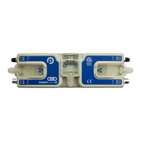
ConveyLinx-IO modules are designed to be installed and integrated on or near the mechanical equipment requiring I/O interface to the control system. Each ConveyLinx-IO provides connection points for up to 8 configurable digital inputs or outputs, 24V power supply, and Ethernet network cables. -
Page 16: Hardware Connections
ConveyLinx-IO User’s Guide ARDWARE ONNECTIONS I/O P EFT AND IGHT ORTS Both of these ports utilize a 4-pin M8 male receptacle. Each receptacle is mechanically keyed to assure proper orientation upon plugging in. Each of the two signal pins can be configured as a digital input or output. -
Page 17: Left And Right Female I/O Ports
Each port is a standard M8 Female receptacle. Each receptacle is mechanically keyed to assure proper orientation upon plugging in. FIGURE 4 - CONVEYLINX-IO FEMALE M8 PORT AND MATING M8 CONNECTOR Input Signal Wiring for Female Port Output Signal Wiring for Female Port... -
Page 18: Ethernet Left And Ethernet Right Ports
RJ-45 connectors on the Ethernet cables. Each module is shipped with 3 shrouds. FIGURE 5 – CONVEYLINX-IO WITH LEFT & RIGHT ETHERNET CABLES (COVERS REMOVED) FIGURE 6 - ETHERNET CABLES CONNECTED WITH COVERS ATTACHED... - Page 19 Hardware Connections IP54 protective shroud requires a special tool to properly install the shroud onto the RJ-45 connector. Figure 7 shows Phoenix Contact item 2891547 FL IP 54 Assembly Tool. This tool must be purchased separately FIGURE 7 - PHOENIX CONTACT ETHERNET SWITCH 2891547 FL IP 54 ASSEMBLY TOOL FIGURE 8 - PROTECTIVE SHROUND PLACED ON TOOL FIGURE 9 - SHROUND STRETCHED WITH TOOL...
-
Page 20: Power Connections
ConveyLinx-IO User’s Guide OWER ONNECTIONS IP54 I NSTALLATION Item 17 as depicted in Figure 2 may be unattached to the module when shipped and are included in the module’s shipping box. These items are used to maintain an IP54 installation of the power and Ethernet wiring. - Page 21 Hardware Connections FIGURE 12 - CONNECTION FOR SINGLE OUTPUTS AND LOGIC POWER SUPPLY FIGURE 13 - TYPICAL CONNECTION FOR SEPARATE OUTPUTS AND LOGIC POWER SUPPLIES Publication ERSC-1008 Rev 1.1 – October 2017...
-
Page 22: Power Supply Common Grounding
ConveyLinx-IO User’s Guide OWER UPPLY OMMON ROUNDING Whether logic and digital outputs are powered together or separately; the DC common (“-“) connections on all power supplies should be connected together. One of the power supplies should have its DC common connected to ground. -
Page 23: Status Indicators
Activity LEDs are multi-coloured and context sensitive. The following chart indicates the various meanings of all ConveyLinx-IO LED indicators. Please refer to Figure 2 on page 15 for the item number locations on the module. By definition Blinking is approximately ½ second on/off cycle and Flashing is approximately ¼ second on/off cycle. -
Page 24: Power
ConveyLinx-IO User’s Guide OWER Indicator Item LED State Description Power supply is connected and voltage is within Solid Blue acceptable range Power Slow Blink Blue Outputs power is under 18V Publication ERSC-1008 Rev 1.1 – October 2017... -
Page 25: Auto-Configuration
For the purposes of ConveyLinx; the AAA.BBB.CCC portion of the I.P. address taken together is defined as the Subnet. The DDD value of the address is defined as the Node. For example; if a ConveyLinx-IO has an I.P. address of “192.168.25.20” then its Subnet address is “192.168.25” and its Node is “20”... - Page 26 Node value changed to 20. All downstream ConveyLinx modules will then have their Node values automatically set beginning with 21. Figure 16 shows 2 ConveyLinx-IO and 2 ConveyLinx-Ai2 installed “out of the box” onto, for example, a conveyor. Once the Auto Configuration Master is identified and the Auto-Configuration Procedure is performed; all 4 ConveyLinx modules will have their I.P.
-
Page 27: Connecting Your Pc To Conveylinx Network
Auto-Configuration ONNECTING ONVEY ETWORK Using an Ethernet cable, connect your PC’s Ethernet port to the Auto-Configuration Master as shown below in Figure 18 FIGURE 18 - INITIAL PC CONNECTION TO CONVEYLINX SUBNET It is highly recommended to connect the PC directly to the ConveyLinx network. Avoid trying to connect via Ethernet switches or wireless router/switches. - Page 28 ConveyLinx-IO User’s Guide Please note that number of modules on a single Subnet is limited to 220. FIGURE 19 - DISCOVER PROCEDURE ON CONVEYLINX-AI2 MODULES Publication ERSC-1008 Rev 1.1 – October 2017...
- Page 29 Auto-Configuration FIGURE 20 – TOPOLOGY VIEW AND INITIATING AUTO-CONFIGURE FROM THE SELECTED NODE You can also select the module graphic from the topology view and right click to show the context menu and initiate the Auto-Configuration from there as shown in Figure 21. FIGURE 21 - AUTO-CONFIGURE BY SELECTING NODE IN THE TREE VIEW Publication ERSC-1008 Rev 1.1 –...
- Page 30 ConveyLinx-IO User’s Guide The selected node for Auto-Configuration does not have to be the first module that is connected directly to the PC. The module at the other end of the detected line can also be selected as the Auto-Configuration master as shown in Figure 22.
-
Page 31: Auto Configuration Results
ESULTS When the auto-configuration routine is complete, each ConveyLinx module will automatically reboot. When a ConveyLinx-IO module has been successfully configured and rebooted, its Module Status LED will blink on and off green. Please note that the time to complete the Auto-Configuration procedure is dependent on the number of modules being configured. - Page 32 ConveyLinx-IO User’s Guide FIGURE 24 - AUTO-CONFIGURATION SUCCESS Please note that once a network has been configured; attempting to again Auto-Configure any ConveyLinx module that is not the Auto Configuration Master will not initiate a new Auto Configuration procedure. The ConveyLinx module will detect that it is not the most upstream unit and abort the procedure.
-
Page 33: Trouble-Shooting Failed Auto-Configuration
In instances when the ConveyLinx-IO module detects that its supply voltage has dipped below 16VDC; the ConveyLinx-IO will turn off its digital outputs. The ConveyLinx-IO will keep this state until it has detected that its power supply voltage has risen to at least 21VDC. -
Page 34: Automatic Module Replacement
ODULE EPLACEMENT Once a ConveyLinx-IO module has been configured with its connections and settings (including transparency options and optional ConveyLogix program); this data is automatically stored in its upstream and downstream neighboring modules. This configuration data is automatically updated even if settings and options have been modified since the initial Auto-Configuration by the EasyRoll software for example. - Page 35 Auto-Configuration FIGURE 25 - EASYROLL NETWORK SERVICES TAB AFTER DISCOVERY Publication ERSC-1008 Rev 1.1 – October 2017...
- Page 36 ConveyLinx-IO User’s Guide FIGURE 26 - TOPOLOGY VIEW AND REPLACING THE SELECTED NODE You can also replace a module by selecting the module graphic directly in the topology view, right click to display the context menu, and select “Replace this Node” as shown in Figure 27.
- Page 37 Auto-Configuration FIGURE 27 - MODULE REPLACEMENT FROM TOPOLOGY VIEW Publication ERSC-1008 Rev 1.1 – October 2017...
-
Page 38: Module Replacement Using Replacement Button
EPLACEMENT UTTON You can replace a single ConveyLinx-IO module without using EasyRoll by utilizing the Replacement Button located inside the Left Ethernet cable connection compartment. Simply install the replacement module and connect all sensors, motors, network cables, and power connections. The procedure is illustrated below. -
Page 39: Easyroll Software Configuration Tool
EasyRoll Software Configuration Tool OFTWARE ONFIGURATION NTRODUCTION The EasyRoll Software Configuration Tool is a PC based application that provides the means to configure a ConveyLinx controlled conveyor system. EasyRoll also provides the ability to change ConveyLinx module default parameters. Installing EasyRoll and performing the initial Auto Configuration is described in the previous section ASIC EATURES... -
Page 40: Options For Configuring Your Pc's Ip Address
ConveyLinx-IO User’s Guide PC’ IP A PTIONS FOR ONFIGURING DDRESS Note that your PC’s I.P. address does not have to be in the same subnet as your ConveyLinx modules in order to perform the Auto Configuration procedure with EasyRoll as described in the previous section. However, your PC’s I.P. -
Page 41: Manual I.p. Address Configuration Methods
EasyRoll Software Configuration Tool If your PC is already configured to obtain an IP address automatically; then by simply connecting you PC as shown in Figure 18 - Initial PC Connection to ConveyLinx Subnet is all you have to do to have the PC’s I.P. address configured so you can use EasyRoll I.P. -
Page 42: Using The Network Services Utility
ConveyLinx-IO User’s Guide When you first run EasyRoll; you should see a window similar to this with greyed out status values and blank parameter boxes. Pressing F2 key or clicking the “Advanced Dialog” button will open the Advanced Dialog window. -
Page 43: Method 2 - Change Pc To Match Auto-Config Master
Auto-Configuration Master is the ConveyLinx module with the last I.P. address octet of “.20”. In this example, 2 ConveyLinx-Ai2s and 2 ConveyLinx-IO modules were found and the Auto-Configuration Master is at 192.168.241.20, its serial number is 275463 and has Firmware 4.17... -
Page 44: Method 3 - Change Auto-Config Master I
ConveyLinx-IO User’s Guide 3 - C I.P. A ETHOD HANGE ONFIG ASTER DDRESS In cases where you want to set the Auto-Configuration Master’s I.P. address to something other than the default it used when the Auto Configuration Procedure was performed, you can do this from the same Network Services screen. -
Page 45: Easyroll Main Screen
Advanced Dialog will show the main screen. The main screen is also shown when you first run EasyRoll. Figure 28 - EasyRoll Main Screen shows a typical main screen. FIGURE 28 - EASYROLL MAIN SCREEN FOR CONVEYLINX-IO Publication ERSC-1008 Rev 1.1 – October 2017... -
Page 46: Connecting To Conveylinx
“Refresh” button to enable. Clicking this button will cause the rest of the items (3, 4, and 5) to be populated. ConveyLinx-IO Connection Status –. This indicates whether a remote PLC is currently connected to the module. ConveyLinx-IO Transparency – See section ConveyLinx-IO Transparency Mode below. -
Page 47: Node Identification
EasyRoll Software Configuration Tool DENTIFICATION EasyRollmain screen has a feature identified as “Blink & Wink” that allows you to visually verify the Node you have selected. If a valid Node is selected in the first text box in the “Node No.” area and its information is displayed on the main screen;... -
Page 48: Conveylinx-Io Transparency Mode
When an application calls for additional digital I/O to be localized on such a conveyor network, it is convenient to install ConveyLinx-IO along the conveyor path. However, by default of the Auto-Configuration procedure, the ConveyLinx-IO gets configured along with its neighboring ZPA control ConveyLinx modules and is set up with these zone to zone flow connections. - Page 49 ConveyLinx-Ai2 neighbours. This in essence makes the ConveyLinx-IO “transparent” to the conveyor flow. The conveyor will operate as if the two ConveyLinx conveyor controllers are connected to each other as illustrated in Figure 31 .
-
Page 50: Disabling Transparency Mode
ConveyLinx-IO User’s Guide FIGURE 31 - CONVEYLINX-IO WITH TRANSPARENCY OPTION ENABLED ISABLING RANSPARENCY Transparency is enabled by default during Auto- Configuration. Disabling Transparency mode is done on the EasyRoll main screen by clicking the check box as shown Publication ERSC-1008 Rev 1.1 – October 2017... -
Page 51: Conveylinx Advanced Dialog
Because EasyRoll is used for the entire ConveyLinx family of modules, there will be several tabs shown in the Advanced Dialog screen that are not applicable to the ConveyLinx-IO modules. These will be blank or otherwise disabled when you are connected to a ConveyLinx-IO module. - Page 52 ConveyLinx-IO User’s Guide Upon selecting the Upgrade screen tab, EasyRoll fills in the I.P. address of the range of Nodes entered on the main screen. Click the “Browse” button to open a file selection dialog window. With the “Open” dialog...
- Page 53 EasyRoll Software Configuration Tool In this example, we clicked “Upload ALL” so the selected firmware upgrade file will be sent to all 4 Nodes. The “Output” window will update the progress of the file uploading process. The time it takes for this process will vary depending upon how many Nodes are being...
-
Page 54: Connections Tab
ConveyLinx-IO User’s Guide ONNECTIONS The Connections utility uses EasyRoll to instruct a given ConveyLinx module to make a logical connection to another ConveyLinx module that it otherwise would not have made during the Auto-Configuration Procedure. For applications where you have more than one ConveyLinx Subnet, this would be the way to logically connect the most downstream Node of one Subnet to the most upstream Node of another Subnet. -
Page 55: Connecting To A Remote Plc Controller
EMOTE ONTROLLER ConveyLinx-IO is a device that requires a remote PLC controller to connect and transfer data to control its digital I/O points. This section describes the network architecture utilized for the module and provides the data mapping details to access I/O for the 3 main protocols that the module recognizes. -
Page 56: Modbus Assembly Instance Structure
NSTANCE TRUCTURE Each ConveyLinx-IO utilizes Modbus register architecture for remote data access over Ethernet. Modbus TCP is a simple protocol for data exchange based upon a query/response mechanism. Each module’s memory structure contains a fixed array of internal data locations that are constructed as Modbus Holding Registers. Each module has a fixed reserve of Holding Registers with each capable of holding a 16-bit numerical integer value. -
Page 57: Ethernet I/P Assembly Instance Structure
Connecting to a Remote PLC Controller Any Modbus TCP capable PC or PLC can connect to any ConveyLinx-IO visible on its network and access Input and Output Holding Register Assemblies. ConveyLinx supports the following Modbus TCP Service Codes: • Service Code 3 - Read Holding Register (up to 45 registers per instruction) •... -
Page 58: Profinet Io Assembly Instance Structure
ConveyLinx-IO User’s Guide These instances essentially group the appropriate Modbus registers into contiguous Input and Output array image that fit into the Allen-Bradley Logix 5000 controller tags. Please refer to Connecting ConveyLinx to Rockwell PLC’s – Insight Automation publication ERSC-1520 for details on how to connect ConveyLinx to Rockwell Ethernet I/P capable PLCs. -
Page 59: Conveylinx Io Configuration Data
Connecting to a Remote PLC Controller IO C ONVEY ONFIGURATION The configuration data is sent from the controller to the module upon initial connection in order to set optional module operational parameters. EGISTER HART EGEND M: 4:1502 Indicates Modbus TCP Addressing Notation E: I.Data[2] Indicates Ethernet I/P Addressing Notation ONFIGURATION... -
Page 60: Note ①
ConveyLinx-IO User’s Guide Register Name / Assembled Address Description Module Address for PLC Outputs Polarity Configuration 0 = Output signal and logic states equal 1 = Invert logic from signal state bit 0 : Left Male Pin2 bit 1 : Left Female Pin2... -
Page 61: Note ②
Connecting to a Remote PLC Controller logical state of the Pin’s data seen in the Inputs register of the Inputs Assembly will be inverted from the logical state of the electrical signal on the Pin. This is provided as a convenience for the remote controller programmer. For example, the remote controller could have re-useable code or routines that expect a photo sensor to have its electrical signal ON when it is “blocked”. -
Page 62: Note ⑤
ConveyLinx-IO User’s Guide -IO PLC) NPUT SSEMBLY ONVEY Register Name / Assembled Address Description Module Address for PLC Bitwise Value - Read only bit 00 = Left Male Pin 2 bit 01 = Left Female Pin 2 bit 02 = Right Male Pin 2... -
Page 63: Appendixa - Module Specifications
Appendix A – Module Specifications A – M PPENDIX ODULE PECIFICATIONS ODULE IMENSIONS Dimensions in mm Publication ERSC-1008 Rev 1.1 – October 2017... -
Page 64: Mounting Dimensions
ConveyLinx-IO User’s Guide OUNTING IMENSIONS NVIRONMENTAL AND LECTRICAL Power supply Voltage 24.0V +/- 10 % Standby current consumption less than 70mA Minimum Operating Voltage Maximum Operating Voltage Storage temperature -40C to 120C(-40F to 248F) Ambient Operating temperature 0C to 50C(32F to 122F) -
Page 65: Inputs
Appendix A – Module Specifications NPUTS • PNP/NPN Auto-sensing (Default) Inputs • Up to 8 per module - 2 inputs per port • Programmable Push-Pull selectable Minimum ON current 1.5mA Maximum OFF current 0.4mA Short Circuit protection( per side) 500mA max Sensor port inputs are auto-sensing for the connected circuit type of either PNP or NPN. -
Page 67: Appendix B - Connecting To Rockwell Ethernet I/P Plc
Appendix B – Connecting to Rockwell Ethernet I/P PLC B – C I/P PLC PPENDIX ONNECTING TO OCKWELL THERNET In RSLogix-5000, when you add a new module in your Ethernet tree, you select “Generic Ethernet Module” from the “Communication” category as shown below in Figure 33: FIGURE 33 - RSLOGIX 5000 SELECT MODULE TYPE SCREEN When you click “Create”, you get the new module configuration window as shown below in Figure 34 . - Page 68 Generic Ethernet Module. When the program is actually downloaded to the PLC processor and begins communications with ConveyLinx-IO; the data exchanged will be the quantity of bytes entered when the module was created. For ConveyLinx-IO this is Configuration Assembly Instance 128 with a size of 10 bytes as shown in Figure 34.
-
Page 69: Appendix C - Connecting To Siemens Profinet-Io Plc
ConveyLinx-IO supports PROFINET I/O and can be used as a remote I/O module to any Siemens Profinet I/O capable PLC. ConveyLinx-IO only exchanges 2 input bytes and 2 output bytes with the PLC so it uses very little of the PLC’s available I/O memory. -
Page 71: Appendixd - Understanding Ip Addresses And Subnets
Appendix D – Understanding IP Addresses and Subnets D – U IP A PPENDIX NDERSTANDING DDRESSES AND UBNETS , IP A ONVEY DDRESSES UBNETS In order to connect to a ConveyLinx network and/or utilize and manage a multiple subnet ConveyLinx conveyor installation;... -
Page 72: Configuration Example
ConveyLinx-IO User’s Guide FIGURE 37 - AVAILABLE SUBNETS PER TYPICAL SUBNET MASK VALUES As you can see, by simply manipulating the Subnet Mask values, you can configure your PC to see multiple ConveyLinx networks. ONFIGURATION XAMPLE Your PC’s I.P. address is used by an Ethernet network to identify the PC on a network. For most office networks, the I.P. - Page 73 Appendix D – Understanding IP Addresses and Subnets FIGURE 38 - IP ADDRESS CONFIGURATION EXAMPLE Please Note: The ConveyLinx IP address structure is designed such that all ConveyLinx last octet (DDD) of their address is greater than or equal to 20 and less than or equal to 240. This leaves 36 spare valid addresses (256 – 220 = 36) on the same Subnet for other devices such as PC’s and PLC’s.
-
Page 75: Notes
OTES Publication ERSC-1008 Rev 1.1 – October 2017... - Page 76 Publication ERSC-1008 Rev 1.1 – October 2017...
Need help?
Do you have a question about the ConveyLinx-IO and is the answer not in the manual?
Questions and answers