Pulseroller ConveyLinx-Ai2 User Manual
Hide thumbs
Also See for ConveyLinx-Ai2:
- User manual (116 pages) ,
- User manual (76 pages) ,
- Connecting (46 pages)

Related Manuals for Pulseroller ConveyLinx-Ai2


Summary of Contents for Pulseroller ConveyLinx-Ai2
- Page 1 ConveyLinx-Ai2 User's Guide Version 1.7 — Aug 20, 2020 Copyright © 2020 PULSEROLLER...
-
Page 2: Table Of Contents
Table of Contents 1. About This Manual ..........................3 2. Glossary of Terms ..........................5 3. Getting Started ............................8 4. Module Hardware..........................10 4.1. Identifying Module Components ....................11 4.2. Mounting Dimensions ........................13 4.3. Motor Ports ........................... 15 4.4. - Page 3 7.1.2. Node Identification ........................ 72 7.1.3. ZPA Upstream/Downstream Zone Settings ................73 7.1.3.1. Release Mode ......................74 7.1.3.1.1. Singulation Release....................75 7.1.3.1.2. Train Release ....................... 76 7.1.3.1.3. GAP Train Release....................77 7.1.3.2. T-Zone Settings ......................78 7.1.3.3. ZPA Error and Information .................... 81 7.1.3.4.
- Page 4 7.2.9.4. Lane Full Interface ...................... 141 7.2.9.5. Most Upstream Zone Handshake Interlock..............142 7.2.9.6. Most Downstream Zone Handshake Interlock ............. 144 7.2.9.7. Inverting the Pin 2 Signals ..................145 8. IOX Interface Module .......................... 146 8.1. Wake up and/or Lane Full Interface..................... 148 8.2.
-
Page 5: About This Manual
The illustrations, charts, sample programs and layout examples shown in this guide are intended solely for purposes of example. Since there are many variables and requirements associated with any particular installation, Pulseroller does not assume responsibility or liability (to include intellectual property liability) for actual use based on the examples shown... - Page 6 PULSEROLLER ConveyLinx-Ai2 User's Guide - 1.7 Reproduction of the contents of this manual, in whole or in part, without written permission of Pulseroller is prohibited Not Included in this Manual Because system applications vary; this manual assumes users and application engineers have properly sized their power distribution capacity per expected motor loading and expected operational duty cycle.
-
Page 7: Glossary Of Terms
2 MDR conveyor zones. The modules allow connection for ConveyLinx-Ai2 Senergy-Ai platform motor rollers and gear drives. The term Module will be used within this document and will refer to the ConveyLinx-Ai2 device Dynamic Host Configuration Protocol A protocol for assigning IP addresses to devices DHCP on a network from a pool of available IP’s. - Page 8 PulseRoller brand proprietary motor control platform that provides electronic intelligence Senergy-Ai inside the motor that can be read by ConveyLinx-Ai and ConveyLinx-Ai2 control modules. The connection from the motor to the controller is via 4-Pin M8 style connector Conveyor control method for zoned controlled conveyor that dictates that when a zone...
- Page 9 PULSEROLLER ConveyLinx-Ai2 User's Guide - 1.7 A basic (linear or curved) cell of the conveyor consisting of a set of slave rollers driven Zone by one or more MDR’s and a single photo-sensor. Zero Pressure Accumulation – Term that describes the conveyor controls and...
-
Page 10: Getting Started
PULSEROLLER ConveyLinx-Ai2 User's Guide - 1.7 3. Getting Started Purpose of this Manual The purpose of this manual is to: • Identify the components and ports available on a module • Provide guidelines for proper installation and wiring • Provide examples on basic inter-module connections for linear conveyor •... - Page 11 PULSEROLLER ConveyLinx-Ai2 User's Guide - 1.7 Learn about basic navigation through EasyRoll Learn about ZPA settings and how to change them How to change motor direction, speed, accel/decel, etc. Learn about motor status and error indicators How to change Jam Timers and Auto-Clear Timers...
-
Page 12: Module Hardware
PULSEROLLER ConveyLinx-Ai2 User's Guide - 1.7 4. Module Hardware Ai2 Modules are designed to be installed and integrated into the conveyor’s mechanical side frame assembly. The Ai2 Module is a controller for up to 2 Motorized Drive Roller (MDR) conveyor zones. Each... -
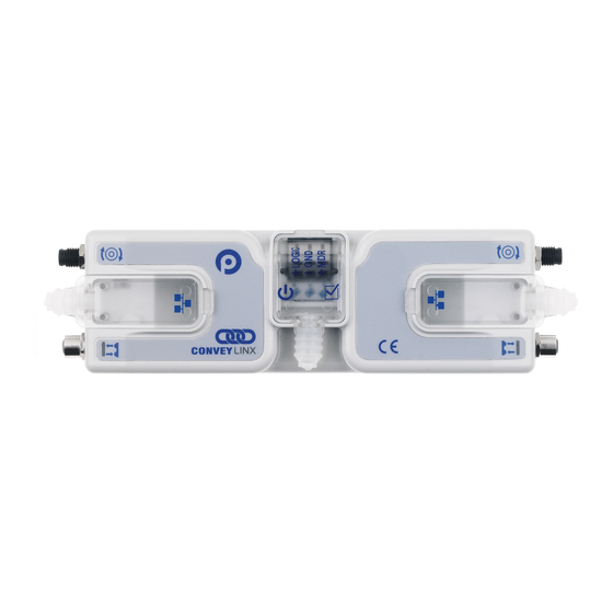
Page 13: Identifying Module Components
PULSEROLLER ConveyLinx-Ai2 User's Guide - 1.7 4.1. Identifying Module Components Item Description 24VDC Power Terminals with separate connections for Logic and Motors Motor Left LED & Motor Right LED – Motor status indicators & Left Sensor & Right Sensor Status LED Indicators &... - Page 14 PULSEROLLER ConveyLinx-Ai2 User's Guide - 1.7 Removable IP54 Ethernet RJ-45 Port Compartment Cover – Left and Right IP54 Protection Shrouds for Ethernet cabling and power wiring • Indicates items shipped unattached to the modue but are included in the module’s box...
-
Page 15: Mounting Dimensions
PULSEROLLER ConveyLinx-Ai2 User's Guide - 1.7 4.2. Mounting Dimensions Mounting Hole Dimensions Page 13 of 154... - Page 16 PULSEROLLER ConveyLinx-Ai2 User's Guide - 1.7 Last modified: Jul 20, 2020 Page 14 of 154...
-
Page 17: Motor Ports
PULSEROLLER ConveyLinx-Ai2 User's Guide - 1.7 4.3. Motor Ports Both ports utilize a 4-pin M8 male receptacle. Each receptacle is mechanically keyed to assure proper orientation upon plugging in. M8 4 Pin Male Motor Port with Senergy Ai Motor Female Connector... -
Page 18: Sensor Ports
PULSEROLLER ConveyLinx-Ai2 User's Guide - 1.7 4.4. Sensor Ports Each sensor port is a standard M8 Female receptacle with standard pin-out: Signal Description 24VDC Module’s 24VDC Supply Aux I/O I/O Signal – Input or Output Function configured with EasyRoll software Module’s DC Common... -
Page 19: Electrical Connections For Sensor Port Aux I/O
PULSEROLLER ConveyLinx-Ai2 User's Guide - 1.7 4.4.1. Electrical Connections for Sensor Port Aux I/O When connecting to either Sensor port with an M8 connector to access Pin 2 signal; you typically will use a standard parallel type splitter cable assembly that breaks out each of the available pins on the Module to their own M8 connection port. - Page 20 PULSEROLLER ConveyLinx-Ai2 User's Guide - 1.7 Aux I/O Pin 2 Input Connection Diagram Because the auto-sensing circuit requires a nominal voltage in order to operate, there will be some small amount of leakage current possible between Module Pin 2 and Pin 3 (GND).
-
Page 21: Ethernet Ports
PULSEROLLER ConveyLinx-Ai2 User's Guide - 1.7 4.5. Ethernet Ports Both ports are standard RJ-45 jacks conforming to standard Ethernet connection pin-out. In order to maintain IP54 rating; Ethernet cables need to be equipped with protective shrouds. Shown below are the Ethernet cables installed using shrouds to protect the RJ-45 connectors on the Ethernet cables. - Page 22 PULSEROLLER ConveyLinx-Ai2 User's Guide - 1.7 How to install shrouds on Ethernet cables Assembly Tool Phoenix Contact Part Number 2891547 FL IP 54 Tool must be purchased separately Putting the shroud on the cable 1: With tool 2: Grip the handle...
-
Page 23: Power Connections
PULSEROLLER ConveyLinx-Ai2 User's Guide - 1.7 4.6. Power Connections IP54 Power Wiring Connection The protective shrouds (Item 17 as depicted in Identifying Module Components) will be unattached to the module when shipped and are included in the module’s shipping box. These shrouds are used to maintain an IP54 installation of the power and Ethernet wiring. - Page 24 PULSEROLLER ConveyLinx-Ai2 User's Guide - 1.7 Logic & MDR Power The Ai2 Module is designed to allow for separate power connections for module logic and motor power so that these can be powered by separate power supplies. For example, the motor power supply can be switched off by an emergency stop control system so that all motors have power removed.
- Page 25 PULSEROLLER ConveyLinx-Ai2 User's Guide - 1.7 logic only power supply remains on Power Supply Common Grounding Whether logic and MDR are powered together or separately; the DC common (“-“) connections on all power supplies should be connected together. One of the power supplies should have its DC common connected to ground.
- Page 26 PULSEROLLER ConveyLinx-Ai2 User's Guide - 1.7 Last modified: Aug 18, 2020 Page 24 of 154...
-
Page 27: Power Supply Sizing
The current values are at rated speed and at rated torque. The current will be less if rated torque is not required by the motor. Pulseroller assumes the user is aware of MDR power requirements for the application and that the user and/or installer have properly sized 24VDC power supplies and wiring based upon all applicable codes and standards. -
Page 28: Led Status Indicators
PULSEROLLER ConveyLinx-Ai2 User's Guide - 1.7 4.8. LED Status Indicators Ai2 Module status is indicated by several LED’s. All LED’s with the exception of the Ethernet Link and Activity LEDs are multi-colored and context sensitive. The following sections indicate the various meanings of all LED indicators. - Page 29 PULSEROLLER ConveyLinx-Ai2 User's Guide - 1.7 Network & Module Status Indicator Item LED State Description Blinking Red Module is starting task processes Blinking Green Module is ready Flashing Green & Module is in Failsafe Mode Blinking Red Module Status Flashing Red...
- Page 30 PULSEROLLER ConveyLinx-Ai2 User's Guide - 1.7 Power Indicator Item LED State Description Power supply for both Logic and Motors are Solid Blue connected Power Blinking Blue Motor power supply is less than 18V Special Cases Indicator Item LED State Description All Sensor &...
-
Page 31: Technical Specifications
PULSEROLLER ConveyLinx-Ai2 User's Guide - 1.7 4.9. Technical Specifications Power Connector Power connector is Degson DG245-5.0 Electrical Ratings Power supply voltage 24.0V +/- 10% Standby current consumption < 120mA Motor Starting Current ≤ 8A Motor Rated Current ≤ 3A Maximum Ratings... - Page 32 PULSEROLLER ConveyLinx-Ai2 User's Guide - 1.7 Certifications & Standards BDS EN 61131-2:2008 Programmable controllers — Part 2: Equipment requirements and tests Electromagnetic compatibility (EMC) — Part 6-2: Generic standards – BDS EN 61000-6-2:2006 Immunity for industrial environments BDS EN Electromagnetic compatibility (EMC) — Part 6-4: Generic standards –...
- Page 33 PULSEROLLER ConveyLinx-Ai2 User's Guide - 1.7 Sensor Port I/O Each Module is equipped with two 4-pin female M8 style Sensor I/O ports primarily used to connect a photo- electric sensor to the module. Each of these ports has one pin dedicated as an input for the sensor (pin 4) and one Aux I/O pin (pin 2) that is configurable to be either an input or an output.
- Page 34 PULSEROLLER ConveyLinx-Ai2 User's Guide - 1.7 Sensor Port 24VDC (Pin 1) and GND (Pin 3) Pin 1 of each Sensor Port provides 24V for powering up a sensor device and/or for supplying the load for the Aux I/O (Pin 2) when configured as an output. The available current for the two control ports on the module is limited internally by a solid-state fuse.
- Page 35 PULSEROLLER ConveyLinx-Ai2 User's Guide - 1.7 cause damage to the high-side bridge transistors. When operating these outputs as general purpose outputs, the high-side transistors are disabled, so a pin-to-ground short-circuit is not an issue Motor Ports in Digital Output Mode Either the Left or Right (or both) Motor Ports can be configured to operate their respective motor coil output transistors as 24V DC digital output signals.
- Page 36 PULSEROLLER ConveyLinx-Ai2 User's Guide - 1.7 Ethernet • 3 port integrated switch ( 2 external ports and 1 port for the on-board processor) • Automatic speed setup (10Base-T / 100Base-TX) • Automatic duplex configuration (Full / Half) • Automatic straight/crossover cable detection ( Auto MDI/MDI-X) •...
-
Page 37: Auto-Configuration
PULSEROLLER ConveyLinx-Ai2 User's Guide - 1.7 5. Auto-Configuration The purpose of Auto-Configuration for networked ConveyLinx controls is to provide a simple and easy procedure for linear conveyor system commissioning. The Auto-Configuration Procedure requires the use of EasyRoll on a PC. -
Page 38: Device Connections To Modules
PULSEROLLER ConveyLinx-Ai2 User's Guide - 1.7 5.1. Device Connections to Modules Before the Auto-Configuration Procedure can be performed; each individual Ai2 Module needs to have its associated MDR’s and photo-sensors connected in the proper way for expected operational results. In general, each Ai2 Module detects which Sensor ports have a device connected and will use this to determine its specific configuration once it has been instructed to self-configure by the Auto-Configuration Procedure. - Page 39 PULSEROLLER ConveyLinx-Ai2 User's Guide - 1.7 1 zone controller with 2 MDR’s and 1 photo-sensor with Sensor on Left or Right Side Last modified: Aug 18, 2020 Page 37 of 154...
-
Page 40: Examples That Will Generate Errors
PULSEROLLER ConveyLinx-Ai2 User's Guide - 1.7 5.1.1. Examples that will generate errors These examples are not necessarily invalid and will not cause the Auto Configuration procedure to fail or abort, but they will result in module errors in ZPA Mode. -
Page 41: Motor Rotation Definition
PULSEROLLER ConveyLinx-Ai2 User's Guide - 1.7 5.2. Motor Rotation Definition The Ai2 Module uses a Clock-Wise (CW) and Counter Clock-Wise (CCW) motor rotation definition. The reference for this distinction is based upon viewing the MDR from the cable exit end of the roller. -
Page 42: Node Connections For A Subnet
PULSEROLLER ConveyLinx-Ai2 User's Guide - 1.7 5.3. Node Connections for a Subnet With your motors and sensor connected to your individual Ai2 Modules, you will need to connect the Ethernet network cabling from module to module in a daisy chain fashion. The most upstream module in the direction of flow is node 1. - Page 43 PULSEROLLER ConveyLinx-Ai2 User's Guide - 1.7 Subnet showing one module on the opposite side of conveyor Last modified: Aug 18, 2020 Page 41 of 154...
-
Page 44: Installing Easyroll
ConveyLinx-Ai2 User's Guide - 1.7 5.4. Installing EasyRoll The files for EasyRoll can be download for free at www.pulseroller.com and will be typically in a compressed (i.e. “.zip”) format. Once you have extracted the contents of the compressed file; the result will be a folder named with the format “EasyRoll_Vx_nn”... -
Page 45: Conveylinx Ethernet Definition
PULSEROLLER ConveyLinx-Ai2 User's Guide - 1.7 5.5. ConveyLinx Ethernet Definition All Ai2 Modules communicate over Ethernet network and use TCP/IP based protocols for normal function. All TCP/IP protocols require that each device on a network have a unique I.P. address assigned to it in order to function properly. - Page 46 PULSEROLLER ConveyLinx-Ai2 User's Guide - 1.7 An Example Here is a 4-module network with possible I.P. addresses that could have been on the module from the factory. Note that their Subnets could be different as well as there could be duplicate addresses.
-
Page 47: Connecting Your Pc To The Network
PULSEROLLER ConveyLinx-Ai2 User's Guide - 1.7 5.6. Connecting Your PC to the Network You can connect your PC to a ConveyLinx network with a standard RJ-45 Ethernet cable at either end of the string of modules. It is highly recommended to connect the PC directly to the ConveyLinx network. Avoid trying to connect via Ethernet switches or wireless router/switches. -
Page 48: Auto-Configuration Procedure
PULSEROLLER ConveyLinx-Ai2 User's Guide - 1.7 5.7. Auto-Configuration Procedure The direction of flow of the conveyor dictates how to begin the Auto-Configuration procedure. The Module located at the most upstream or in-feed end of the conveyor is defined as the Auto-Configuration Node. The Auto-Configuration procedure is initiated from the Auto-Configuration Node. - Page 49 PULSEROLLER ConveyLinx-Ai2 User's Guide - 1.7 For the Auto-Configuration to work properly, all loads, totes, product, containers, cartons, etc. must be removed from the entire conveyor path and all photo-sensors must be aligned and adjusted so that none are detecting that their respective zone is occupied. Failure to...
- Page 50 PULSEROLLER ConveyLinx-Ai2 User's Guide - 1.7 After a few seconds, the discovered Modules appear in the module table, click the AutoConfig button Page 48 of 154...
- Page 51 PULSEROLLER ConveyLinx-Ai2 User's Guide - 1.7 After a few seconds each Module is shown in physical topology order from the PC If the most upstream module is the one closest to the PC, select it, then right click and select AutoConfig from Here.
- Page 52 PULSEROLLER ConveyLinx-Ai2 User's Guide - 1.7 When the procedure is done, you will see the text go from red to black and you will notice that the I.P. addresses have updated per the direction of flow To Change the Direction of Flow – Select the Module at the Opposite End of the...
- Page 53 PULSEROLLER ConveyLinx-Ai2 User's Guide - 1.7 When the procedure is done, you will see the text go from red to black and you will notice that the I.P. addresses have updated per the direction of flow Please note that the time to complete the Auto-Configuration Procedure is dependent on the number of modules being configured.
-
Page 54: Expected Results
PULSEROLLER ConveyLinx-Ai2 User's Guide - 1.7 5.8. Expected Results When the Auto-Configuration Procedure routine is complete, each Ai2 Module will automatically reboot. When a Ai2 Module has been successfully configured and rebooted, its Module Status LED will blink on and off green. - Page 55 PULSEROLLER ConveyLinx-Ai2 User's Guide - 1.7 function will display all modules that it finds and from the list your most upstream Ai2 Module should have the 4th octet of its IP Address as .20 and you should see each module you configured in the list.
-
Page 56: What To Do If Things Go Wrong
PULSEROLLER ConveyLinx-Ai2 User's Guide - 1.7 5.9. What to do if things go wrong Module Status LEDs Blinking Green with unexpected results • Check that all sensors are operational and that all zones are clear then perform procedure again. How to change block/clear sensor logic without having to perform another Auto-Configuration •... -
Page 57: Default Settings And Operation
PULSEROLLER ConveyLinx-Ai2 User's Guide - 1.7 6. Default Settings and Operation After Auto-Configuration, the modules on your newly configured network are in ZPA mode and set to Singluation Release. If all module and/or Network Status LED’s are blinking green; then to fully verify configuration is to place a single carton onto the most upstream zone and see that it conveys to the discharge zone. -
Page 58: Singulation Release Mode
PULSEROLLER ConveyLinx-Ai2 User's Guide - 1.7 6.1. Singulation Release Mode Singulation Release is the mode where the Ai2 Module requires that its neighboring downstream zone must be clear before it releases an item. All 3 Cartons are accumulated Carton 1 releases – Cartons 2... -
Page 59: Flex Zone Recognition
PULSEROLLER ConveyLinx-Ai2 User's Guide - 1.7 6.2. Flex Zone Recognition Ai2 Modules will automatically detect that a given carton is longer than one zone length and automatically adjust accumulation control so that the longer carton occupies two logical zones and will keep the next upstream carton from conveying into the longer carton. - Page 60 PULSEROLLER ConveyLinx-Ai2 User's Guide - 1.7 Operating conveyor system with cartons whose lengths are in excess of 2 zone lengths may produce undesirable results such as excessive detected jam conditions and faults. How to disable Flex Zone operation with EasyRoll...
-
Page 61: Jam Conditions
PULSEROLLER ConveyLinx-Ai2 User's Guide - 1.7 6.3. Jam Conditions There are two (2) types of Jam conditions detected by the Ai2 Module: Sensor Jam Arrival Jam Both of these Jam conditions utilize a single Jam Timer that has to expire in order for the condition to be active. -
Page 62: Arrival Jam
PULSEROLLER ConveyLinx-Ai2 User's Guide - 1.7 6.3.1. Arrival Jam When a carton leaves an upstream zone and is conveyed to its next downstream zone, this upstream zone expects positive confirmation of carton arrival from the downstream zone. This communication occurs automatically along the ConveyLinx network. - Page 63 PULSEROLLER ConveyLinx-Ai2 User's Guide - 1.7 How to Disable Arrival Jam How to change the Jam and Auto Clear Timers Last modified: Aug 18, 2020 Page 61 of 154...
-
Page 64: Sensor Jam
PULSEROLLER ConveyLinx-Ai2 User's Guide - 1.7 6.3.2. Sensor Jam While a zone is releasing a carton; if this carton remains blocking the photo-sensor for the Jam Timer period (default of 5 seconds), the Ai2 Module will detect a Sensor Jam. This will be indicated on the corresponding... - Page 65 PULSEROLLER ConveyLinx-Ai2 User's Guide - 1.7 3. Run the zone motor forward to attempt discharge to the downstream zone (Attempt #1 complete) 4. If sensor is still blocked after discharge attempt, the zone motor runs in reverse until the sensor is clear or 1 second has elapsed, whichever happens first 5.
-
Page 66: Automatic Module Replacement
PULSEROLLER ConveyLinx-Ai2 User's Guide - 1.7 6.4. Automatic Module Replacement Once a linear conveyor has been commissioned by Auto-Configuration Procedure, the Ai2 Module store configuration data about its upstream and downstream neighboring modules. This configuration data is automatically updated even if the linear conveyor has had its parameters modified by the EasyRoll software. - Page 67 PULSEROLLER ConveyLinx-Ai2 User's Guide - 1.7 Module Replacement Using Replacement Button Disconnect existing module’s motor(s), network, photo-sensor(s), and power connections. The order of disconnection does not matter. Connect new module’s motor(s), sensor(s), network connections and power connections. The Module Replacement Button is located in the Left Ethernet cable compartment.
-
Page 68: Reset To Factory Default Settings
PULSEROLLER ConveyLinx-Ai2 User's Guide - 1.7 6.5. Reset to Factory Default Settings There may be instances when you want to return a Ai2 Module to its “factory default” state. The procedure to do this is the following: 1. Unplug all sensors, devices,... - Page 69 PULSEROLLER ConveyLinx-Ai2 User's Guide - 1.7 Control Ports All Options Unchecked Sensors Sensors are “ON is Blocked” Connections All are Cleared Last modified: Aug 18, 2020 Page 67 of 154...
-
Page 70: Easyroll Software
PULSEROLLER ConveyLinx-Ai2 User's Guide - 1.7 7. EasyRoll Software We introduced the EasyRoll software in section Auto-Configuration. In that section the software installation, connecting to your PC and using the Advanced Dialog to Discover and AutoConfigure your modules was covered. -
Page 71: Main Screen
PULSEROLLER ConveyLinx-Ai2 User's Guide - 1.7 7.1. Main Screen Indicator Description Network IP – This is where you enter the Subnet of the particular ConveyLinx network you wish to connect Node No. – This is where you enter a range of Nodes in which to connect. Entering values here will cause the “Refresh”... - Page 72 PULSEROLLER ConveyLinx-Ai2 User's Guide - 1.7 operation of certain jam conditions, etc. Upstream Zone / Downstream Zone – Selector to cause the local zone to Accumulate if a carton arrives and to cause the local zone to be in Accumulate mode upon power up of the module Left MDR / Right MDR –...
-
Page 73: Node Navigation
PULSEROLLER ConveyLinx-Ai2 User's Guide - 1.7 7.1.1. Node Navigation Whatever value is entered in the From Node # box will be the particular module Node data shown in the remainder of the main screen. The value entered in the To Node # box does not have to be the actual “last”... -
Page 74: Node Identification
PULSEROLLER ConveyLinx-Ai2 User's Guide - 1.7 7.1.2. Node Identification EasyRoll main screen has a feature identified as “Blink & Wink” that allows you to visually verify the Node you have selected If a valid Node is selected in the From Node # text box and its information is displayed on the main screen;... -
Page 75: Zpa Upstream/Downstream Zone Settings
PULSEROLLER ConveyLinx-Ai2 User's Guide - 1.7 7.1.3. ZPA Upstream/Downstream Zone Settings On the main screen there are areas to configure the Upstream and Downstream Zone settings. The Upstream and Downstream settings are set independent of one another so you can customize your ZPA functionality based upon your specific needs. -
Page 76: Release Mode
PULSEROLLER ConveyLinx-Ai2 User's Guide - 1.7 7.1.3.1. Release Mode Selecting the pull-down box for ZPA Mode will show the available selections. Singulation is the default configuration Selecting a new setting from the ZPA Mode drop down box immediately changes the zone’s mode. -
Page 77: Singulation Release
PULSEROLLER ConveyLinx-Ai2 User's Guide - 1.7 7.1.3.1.1. Singulation Release Singulation Mode is the default setting and it is described in the Default Settings and Operation section Last modified: Jul 30, 2020 Page 75 of 154... -
Page 78: Train Release
PULSEROLLER ConveyLinx-Ai2 User's Guide - 1.7 7.1.3.1.2. Train Release All 3 Cartons are Accumulated When Carton 1 releases – Cartons 2 and 3 also release at the same time Select Train from the pull-down box for Train Mode Please note that starting many zones in Train Release mode particularly with heavy loads can cause voltage drops on your power supplies. -
Page 79: Gap Train Release
PULSEROLLER ConveyLinx-Ai2 User's Guide - 1.7 7.1.3.1.3. GAP Train Release All 3 Cartons are Accumulated When Carton 1 releases and Zone 2’s GAP time has expired, Carton 2 will begin to release. Carton 3 remains accumulated When Carton 2 releases and Zone 3’s... -
Page 80: T-Zone Settings
PULSEROLLER ConveyLinx-Ai2 User's Guide - 1.7 7.1.3.2. T-Zone Settings In conveyor applications, transferring a carton at a right angle from one conveyor to another often requires special lifting and lowering mechanisms. In certain applications, one conveyor can simply drive its carton off of its downstream zone directly onto the upstream zone of another conveyor that is perpendicularly oriented. - Page 81 PULSEROLLER ConveyLinx-Ai2 User's Guide - 1.7 T-Zone Between 2 Separate Modules Page 79 of 154...
- Page 82 PULSEROLLER ConveyLinx-Ai2 User's Guide - 1.7 T-Zone on a Single Module Enter the value and click the Set button. In this example we entered 1.5 seconds. Whether to change the Upstream Zone or Downstream Zone value on the main screen is dependent upon which zone is...
-
Page 83: Zpa Error And Information
PULSEROLLER ConveyLinx-Ai2 User's Guide - 1.7 7.1.3.3. ZPA Error and Information There is an Error and Information area in the upper right corner in both the Upstream and Downstream Zone areas of the Main Screen. There is an indicator that shows if a Jam condition is active (either... -
Page 84: Accumulate Control From Main Screen
PULSEROLLER ConveyLinx-Ai2 User's Guide - 1.7 7.1.3.4. Accumulate Control from Main Screen Clicking the Accumulate switch icon will place the zone in accumulation mode and the next carton that arrives at that zone will stop and remain until you click the switch again to turn off the accumulation mode... -
Page 85: Settings Checkboxes
PULSEROLLER ConveyLinx-Ai2 User's Guide - 1.7 7.1.3.5. Settings Checkboxes Both the Upstream and Downstream ZPA Zones have Settings check boxes to allow you to customize some of the ZPA behavior. These settings can apply to only the zone you are connected to and viewing or you can apply the same settings to multiple modules in a range of module nodes. -
Page 86: Disable Reset Delays
PULSEROLLER ConveyLinx-Ai2 User's Guide - 1.7 7.1.3.5.1. Disable Reset Delays Any individual zone or group of zones can be configured to ignore the Auto Clear Time delay for either or both of the Arrival Jam Sensor Jam. Clicking either or both check-boxes will cause the zone’s logic to ignore the Auto... -
Page 87: Disable Sensor Jam Auto Clear
PULSEROLLER ConveyLinx-Ai2 User's Guide - 1.7 7.1.3.5.2. Disable Sensor Jam Auto Clear Sensor Jam Auto Clear Procedure describes how the logic will make 3 attempts to clear a Sensor Jam if one occurs. There may be instances at specific zones or range of zones where you do not want this functionality to happen. -
Page 88: Disable Arrival Timeout
PULSEROLLER ConveyLinx-Ai2 User's Guide - 1.7 7.1.3.5.3. Disable Arrival Timeout Arrival Jam describes how default zone to zone logic utilizes the Jam Time value for the discharging zone to wait for the accepting zone to indicate successful arrival of the carton into the accepting zone. In certain... -
Page 89: Disable Manual Operation
PULSEROLLER ConveyLinx-Ai2 User's Guide - 1.7 7.1.3.5.4. Disable Manual Operation In normal ZPA operation, if a zone is in Accumulation (either by external device or if Aux I/O Pin 2 is set to Accumulate) and the carton is subsequently manually removed from the conveyor; the zone downstream of the accumulated zone will run in an attempt to “find the lost carton”. - Page 90 PULSEROLLER ConveyLinx-Ai2 User's Guide - 1.7 When you check the Disable Manual Operations check-box for the Downstream Zone, then it will not run when upstream carton is removed Last modified: Aug 18, 2020 Page 88 of 154...
-
Page 91: Motor Settings
PULSEROLLER ConveyLinx-Ai2 User's Guide - 1.7 7.1.4. Motor Settings The motor settings for the current selected module can be modified on the Main Screen Please note that the Motor Settings grouped by motor plugged into the physical Left and Right sides of the module and are not based upon Upstream or Downstream product flow. -
Page 92: Motor Type
Set All will change Nodes 2 thru 6 to the same setting as Node 1 Please consult the Pulseroller Catalog Senergy Ai motor documentation and review your application if you are unsure as to which motor-type setting to use... -
Page 93: Brake Method
PULSEROLLER ConveyLinx-Ai2 User's Guide - 1.7 7.1.4.2. Brake Method The Brake Method pull-down box lists all the holding brake methods available for the module. Normal is the default setting upon completion of the Auto-Configuration Procedure. The new settings are downloaded to the selected Node upon selecting a new item from the list. -
Page 94: Speed
PULSEROLLER ConveyLinx-Ai2 User's Guide - 1.7 7.1.4.3. Speed The Speed setting value is in meters per second (m/s). The Senergy-Ai motor roller contains data as to its gear reduction ratio and roller diameter that is readable by the Ai2 Module. EasyRoll then uses this information to indicate whether the speed you enter is valid for the connected roller. - Page 95 PULSEROLLER ConveyLinx-Ai2 User's Guide - 1.7 Setting Same Speed for Multiple Modules Type in the desired speed in m/s. You can also use the Set All button to set the entered speed to each motor in the From Node # / To Node # boxes. In this example...
-
Page 96: Rotation Direction
PULSEROLLER ConveyLinx-Ai2 User's Guide - 1.7 7.1.4.4. Rotation Direction This setting is either Clock-Wise (CW) or Counter-Clock Wise (CCW)and is determined for each module based upon the Auto-Configuration Procedure results. Please refer to section Motor Rotation Definition details on how to determine rotation direction with respect to MDR installed orientation. -
Page 97: Acceleration/Deceleration
PULSEROLLER ConveyLinx-Ai2 User's Guide - 1.7 7.1.4.5. Acceleration/Deceleration Acceleration and Deceleration settings are fields you enter values similar to Speed. The units of the value you enter are in mm which means that the control will accelerate and decelerate for the distance specified within the controller’s current limits and the mechanical limits of the connected drive train. -
Page 98: Motor Jog And Error Indicators
PULSEROLLER ConveyLinx-Ai2 User's Guide - 1.7 7.1.4.6. Motor Jog and Error Indicators Motor Jog (Run) Function In EasyRoll, the Left and Right motors have their own Run buttons on the Main Screen. These are used to temporarily run the motors for verification of function and diagnostics. - Page 99 PULSEROLLER ConveyLinx-Ai2 User's Guide - 1.7 Error Indicators In EasyRoll, the Left and Right motors have their own status indicators on the Main Screen. These are used to provide visual indication of certain conditions. There is also status indicators for the Sensors connected to the Left and Right sides of the modules.
- Page 100 PULSEROLLER ConveyLinx-Ai2 User's Guide - 1.7 module temperature has exceeded 90°C A running numerical counter that increments for each occurrence of any of the Motor Error Counter motor error conditions. Counter resets to 0 upon power cycle Overvoltage [>30V] Occurs when the incoming power to the module exceeds 30V...
-
Page 101: Diagnostic Window
PULSEROLLER ConveyLinx-Ai2 User's Guide - 1.7 7.1.5. Diagnostic Window Diagnostic Window Example Indicator Description You can navigate to the next or previous module’s Diagnostic Window by clicking the + and – buttons Displays the current ZPA status of the zone and the state of the sensor Displays the status of the upstream and downstream zones to the selected module. - Page 102 PULSEROLLER ConveyLinx-Ai2 User's Guide - 1.7 Accumulation Status If a carton is accumulated on a particular zone, the Diagnostic Window will indicate a reason for the accumulated state. Also note that in situations where an external device (PLC or PC controller) or the Accumulate icon on the Main Screen has been activated;...
-
Page 103: Advanced Dialog
PULSEROLLER ConveyLinx-Ai2 User's Guide - 1.7 7.2. Advanced Dialog The Advanced Dialog is where you can make further changes to module operation and access utilities to help maintain your system of modules. To invoke the ConveyLinx Advanced Dialog you can do any of the following: •... -
Page 104: Look Ahead And Timing Tab
PULSEROLLER ConveyLinx-Ai2 User's Guide - 1.7 7.2.1. Look Ahead and Timing Tab The Look Ahead and Timing Tab contains 4 sections of settings pertaining to ZPA functionality: Look Ahead Jam & Auto Clear Timers Run After & Induct Sensor Debounce... -
Page 105: Look Ahead Slowdown Feature
PULSEROLLER ConveyLinx-Ai2 User's Guide - 1.7 7.2.1.1. Look Ahead Slowdown Feature The Look Ahead feature configures the logic to “look ahead” to its next downstream zone and if it is occupied when a carton is entering its zone, the module will dynamically adjust the MDR to the selected speed. - Page 106 PULSEROLLER ConveyLinx-Ai2 User's Guide - 1.7 Click the checkbox to enable the Look Ahead feature for the selected Node. Clicking the Set buttons will download the setting to the respective zone on the selected Node. The value entered for the Slow Down Speed is in percent of the Zone’s normal speed as set on the main screen.
- Page 107 PULSEROLLER ConveyLinx-Ai2 User's Guide - 1.7 Fast Release Time The Fast Release Time option allows you to set a delay before the Slow Down Speed is engaged for the slow-down zone When Zone 2 wakes up it will run at normal set...
-
Page 108: Jam & Auto Clear Timers
PULSEROLLER ConveyLinx-Ai2 User's Guide - 1.7 7.2.1.2. Jam & Auto Clear Timers The Jam Timer for a given Upstream or Downstream zone is used for both detecting an Arrival Jam and a Sensor Jam. The Jam Timer should be set as the maximum expected time it takes for a carton to travel from one zone to the next plus a small addition to prevent nuisance jam occurrences. -
Page 109: Run After Time/Distance
PULSEROLLER ConveyLinx-Ai2 User's Guide - 1.7 7.2.1.3. Run After Time/Distance The Run After time value is used by the logic for normal zone discharge. This is the amount of time the zone’s MDR will continue run after its photo-sensor has been clear when discharging to the next downstream zone. - Page 110 PULSEROLLER ConveyLinx-Ai2 User's Guide - 1.7 Run After Distance EasyRoll provides the option to change the Run After metric to be distance based instead of time based. When the metric is distance, the value entered is millimetres instead of seconds...
-
Page 111: Induct Forward Time/Distance
PULSEROLLER ConveyLinx-Ai2 User's Guide - 1.7 7.2.1.4. Induct Forward Time/Distance Induct Forward value is used to cause the MDR to continue to run after the zone’s photo-sensor has been blocked when receiving a carton from upstream. This value is adjustable per zone to compensate for special conditions when for example a zone’s photo-sensor needs to... - Page 112 PULSEROLLER ConveyLinx-Ai2 User's Guide - 1.7 Induct Forward Distance Select Distance from the drop down box and enter new values for upstream and/or downstream Induct Forward pulses and click the corresponding Set button. The default is 0 pulses and the valid range is 0 to 65,535 pulses.
-
Page 113: Sensor Debounce
PULSEROLLER ConveyLinx-Ai2 User's Guide - 1.7 7.2.1.5. Sensor Debounce Sensor Debounce setting is the time the logic holds the state of its Sensor inputs after a change of state. Keep in mind this is not a delay prior to detecting a carton when it first blocks the sensor. The module will detect the leading edge of a carton and hold this state for the Sensor Debounce time period. - Page 114 PULSEROLLER ConveyLinx-Ai2 User's Guide - 1.7 Last modified: Aug 18, 2020 Page 112 of 154...
-
Page 115: Upgrade Tab
PULSEROLLER ConveyLinx-Ai2 User's Guide - 1.7 7.2.2. Upgrade Tab The Upgrade tab screen gives access to the module firmware utility. Over time, enhancements and features may be added to the ConveyLinx family of products. These features and enhancements are typically made available to customers in the form of firmware upgrade files that need to be uploaded to your modules. - Page 116 PULSEROLLER ConveyLinx-Ai2 User's Guide - 1.7 With the Open dialog displayed, navigate to the location on your PC where you placed the firmware upgrade file you received. Select the file and click Open In this example, we clicked Upload ALL so the selected firmware upgrade file will be sent to all 6 Nodes.
- Page 117 PULSEROLLER ConveyLinx-Ai2 User's Guide - 1.7 When all Nodes report back to the Output window with a status of Done; then the upload is complete and you can close the ConveyLinx Advanced Dialog window Please note that you typically arrive at the Upgrade tab from the Network Services tab where you select the modules first and click the Upgrade button there.
-
Page 118: Connections Tab
PULSEROLLER ConveyLinx-Ai2 User's Guide - 1.7 7.2.3. Connections Tab The Connections utility uses EasyRoll to instruct a given module to make a logical connection to another module that it otherwise would not have made during the Auto-Configuration Procedure. For applications... - Page 119 PULSEROLLER ConveyLinx-Ai2 User's Guide - 1.7 Navigate to Node 4 of the 192.168.21 subnet (i.e. 192.168.20.25). Notice that the module’s network data appears in the center. Also notice that the Downstream connection for this Node is None Enter 192.168.22.20 as the I.P. address for Node 4’s new Downstream...
- Page 120 PULSEROLLER ConveyLinx-Ai2 User's Guide - 1.7 Navigate to Node 1 of the 192.168.22 subnet (i.e. 192.168.22.20). Notice that the module’s network data appears in the center. Also notice that the Upstream connection for this Node is None Enter 192.168.21.23 as the I.P. address for Node 1’s new Upstream connection.
-
Page 121: Network Services Tab
PULSEROLLER ConveyLinx-Ai2 User's Guide - 1.7 7.2.4. Network Services Tab The Network Services screen provides multiple functions related to module and network management. These functions are: • Discover and IP Address Set • Backup and Restore • Firmware Upgrade Last modified: Aug 04, 2020... -
Page 122: Discover & Ip Address Set
PULSEROLLER ConveyLinx-Ai2 User's Guide - 1.7 7.2.4.1. Discover & IP Address Set One of the features of EasyRoll is that it has a utility called Discover that allows your PC to go and find any modules that may be physically connected to you network regardless of the I.P. address settings of your PC or the I.P. - Page 123 PULSEROLLER ConveyLinx-Ai2 User's Guide - 1.7 The drop-down box at the top of the list box lets you filter the list by Subnet To change the IP Address, Subnet Mask, etc. of a module, double click it from the list and its data can be modified...
- Page 124 PULSEROLLER ConveyLinx-Ai2 User's Guide - 1.7 Once you have edited the data, click the Set button and the changes are sent to the module Last modified: Aug 18, 2020 Page 122 of 154...
-
Page 125: Backup & Restore
PULSEROLLER ConveyLinx-Ai2 User's Guide - 1.7 7.2.4.2. Backup & Restore ou have the ability to select a Subnet or all Subnets discovered and generate a Backup file that will contain all the parameters and settings for each module included in the selection. This means all motor settings (speed, acceleration, deceleration, braking, etc.), ZPA settings, Advanced Dialog settings, etc. - Page 126 PULSEROLLER ConveyLinx-Ai2 User's Guide - 1.7 Conversely, if you have a Backup file that you want to use to get your Subnet’s settings restored; click the Select ALL button and then click the Restore button. An “Open File” dialog will appear for you to navigate to the location of your backup file, select it and click “Open”.
- Page 127 PULSEROLLER ConveyLinx-Ai2 User's Guide - 1.7 module Serial Number. To do this you follow the same restore procedure as previously shown except you click the Restore by IP button instead of the Restore button Backup and Restore Recommendations and Tips Sometimes there are situations where just because a software application will allow you to do something does not always mean that you should.
-
Page 128: Special Services Tab
PULSEROLLER ConveyLinx-Ai2 User's Guide - 1.7 7.2.5. Special Services Tab Clear Motor Short Circuit Error Another function on the Special Services tab is a button used to clear an MDR short circuit error. This particular error is not logically cleared based upon an elapsed period timeout or other such reset. An MDR short circuit error requires that either the module be powered down and then powered back up or by clicking the Reset button on this tab. - Page 129 PULSEROLLER ConveyLinx-Ai2 User's Guide - 1.7 Touch & Go The Touch & Go function is available in ZPA mode and when activated causes the MDR in the activated zone to sense rotational movement of the MDR in its default direction. If this rotational movement (such as someone pushing a carton onto the zone) is of sufficient duration and speed;...
-
Page 130: Flex Zone Tab
PULSEROLLER ConveyLinx-Ai2 User's Guide - 1.7 7.2.6. Flex Zone Tab Flex Zone feature is enabled by default when you perform the Auto Configure Procedure. There can be certain situations such as higher speed applications and/or applications where a large percentage of cartons are at a length very close to the zone length where a “false triggering”... - Page 131 PULSEROLLER ConveyLinx-Ai2 User's Guide - 1.7 Inter Module Communication Time The Inter Module Communication Time value is used to adjust the behavior of the Flex Zone operation. In situations where carton lengths can be close to the length of the zones (i.e. distance between photoeyes), you may want to adjust Flex Zone operation so that it either engages or not in these situations.
- Page 132 PULSEROLLER ConveyLinx-Ai2 User's Guide - 1.7 The value entered is in msec and it can be thought of as an amount of time added to the logic after the trailing edge of the sensor in order to simulate increasing the carton length.
-
Page 133: Sensors Tab
PULSEROLLER ConveyLinx-Ai2 User's Guide - 1.7 7.2.7. Sensors Tab The Sensors tab displays the status of how the two sensor signals were configured during the Auto Configuration Procedure. If for some reason one or more of the sensors was not configured properly during the Auto Configuration Procedure;... -
Page 134: Extensions Tab
PULSEROLLER ConveyLinx-Ai2 User's Guide - 1.7 7.2.8. Extensions Tab The Extensions Tab allows you to extend or “slave” single or multiple zones to one “master” zone. An example situation could be that you have for example certain length zones and on a given conveyor line there is a need for an extra partial zone that is too short to be a functional zone that accumulates a carton, but at the same time it is long enough that mechanically you need to have an MDR in that zone. - Page 135 PULSEROLLER ConveyLinx-Ai2 User's Guide - 1.7 In the Advanced Dialog, navigate to Node 3 and click the Extensions Tab. Notice that Node 3’s IP address 192.168.21.22 is filled in. In the drop-down box, select Downstream and click Apply. Note that...
- Page 136 PULSEROLLER ConveyLinx-Ai2 User's Guide - 1.7 Now if you navigate back to Node 2 and look at the Connections Tab, you can see that the downstream connection of Node 2 is now Node 4 instead of Node 3 And then when you navigate to Node 4,...
- Page 137 PULSEROLLER ConveyLinx-Ai2 User's Guide - 1.7 And when you navigate to Node 3, you can see that it is configured as an Extension of Node 4 Last modified: Aug 18, 2020 Page 135 of 154...
-
Page 138: Pin 2 Usage Tab
PULSEROLLER ConveyLinx-Ai2 User's Guide - 1.7 7.2.9. Pin 2 Usage Tab Pin 2 on each of the two Sensor port’s M8 connector on the Module is configurable as to its potential function. This pin can function as either an input or an output. The default “out-of-the-box” usage for Pin 2 is “Not Used”. -
Page 139: Most Downstream Zone
PULSEROLLER ConveyLinx-Ai2 User's Guide - 1.7 7.2.9.1. Most Downstream Zone Please note that by default and without any intervention, the most downstream zone will always try to discharge product. To control this, you need to utilize the Aux I/O Pin 2 signal for the most downstream zone as an Accumulate input. -
Page 140: Most Upstream Zone
PULSEROLLER ConveyLinx-Ai2 User's Guide - 1.7 7.2.9.2. Most Upstream Zone By default and without any intervention, the most upstream zone will never turn on to accept new product. To cause the most upstream zone to run to accept an item with a wired signal, you need to utilize the Aux I/ O Pin 2 for the upstream zone as a Wake-up input. -
Page 141: Accumulate Intermediate Zone
PULSEROLLER ConveyLinx-Ai2 User's Guide - 1.7 7.2.9.3. Accumulate Intermediate Zone By default, and without intervention; all zones in between the most upstream and most downstream zones always try to convey items downstream if the next downstream zone is clear. To cause an intermediate zone to accumulate based upon a wired signal, you need to utilize the Aux I/O Pin 2 signal for the zone in questions as an Accumulate input. - Page 142 PULSEROLLER ConveyLinx-Ai2 User's Guide - 1.7 Last modified: Aug 18, 2020 Page 140 of 154...
-
Page 143: Lane Full Interface
PULSEROLLER ConveyLinx-Ai2 User's Guide - 1.7 7.2.9.4. Lane Full Interface A special case of the accumulate signal for the most downstream zone is referred to as Lane Full Interface. When Lane Full Interface is used on the most downstream zone; the input signal is treated with a block and clear timer such that when the signal is energized, the signal must remain energized for the “block”... -
Page 144: Most Upstream Zone Handshake Interlock
PULSEROLLER ConveyLinx-Ai2 User's Guide - 1.7 7.2.9.5. Most Upstream Zone Handshake Interlock In applications where the equipment feeding the most upstream zone of ConveyLinx controlled conveyor requires a handshake interlock to know when the most upstream zone of the ConveyLinx controlled conveyor is empty and ready to accept a new item, this can be achieved by utilizing both the Left and Right Aux I/O Pin signals. - Page 145 PULSEROLLER ConveyLinx-Ai2 User's Guide - 1.7 Then we select Product on Zone for the Right Pin 2 signal and click the diagonal arrow to indicate that this signal is to reflect the status of the Upstream zone Last modified: Aug 18, 2020...
-
Page 146: Most Downstream Zone Handshake Interlock
PULSEROLLER ConveyLinx-Ai2 User's Guide - 1.7 7.2.9.6. Most Downstream Zone Handshake Interlock In applications where the equipment accepting product from the most downstream zone of ConveyLinx controlled conveyor requires a handshake interlock to know when the most downstream zone of the ConveyLinx controlled conveyor is occupied and ready to discharge the item, this can be achieved by utilizing both the Left and Right Aux I/O Pin signals. -
Page 147: Inverting The Pin 2 Signals
PULSEROLLER ConveyLinx-Ai2 User's Guide - 1.7 7.2.9.7. Inverting the Pin 2 Signals On this dialog, you can also invert the meaning of the electrical signal by checking the Invert box for either or both Pins. In this example, because we have... -
Page 148: Iox Interface Module
M8 cable accessories to gain access to the Aux I/O pin on the sensor ports. Pulseroller offers a Breakout/Splitter Module Accessory that offers the same cable splitter functionality as the commercially available M8 units along with breaking out some of the signals to convenient wire terminal access for flying lead devices. - Page 149 PULSEROLLER ConveyLinx-Ai2 User's Guide - 1.7 Electrical Schematic Last modified: Aug 04, 2020 Page 147 of 154...
-
Page 150: Wake Up And/Or Lane Full Interface
PULSEROLLER ConveyLinx-Ai2 User's Guide - 1.7 8.1. Wake up and/or Lane Full Interface Last modified: Aug 04, 2020 Page 148 of 154... -
Page 151: Wake Up/Lane Full With Wired Terminals
PULSEROLLER ConveyLinx-Ai2 User's Guide - 1.7 8.2. Wake up/Lane Full with Wired Terminals Last modified: Aug 04, 2020 Page 149 of 154... -
Page 152: Wake Up/Lane Full With Discrete Signals
PULSEROLLER ConveyLinx-Ai2 User's Guide - 1.7 8.3. Wake up/Lane Full with Discrete Signals Last modified: Aug 04, 2020 Page 150 of 154... -
Page 153: Wake Up/Product On Zone Handshake Interlock
PULSEROLLER ConveyLinx-Ai2 User's Guide - 1.7 8.4. Wake up/Product on Zone Handshake Interlock Last modified: Aug 04, 2020 Page 151 of 154... -
Page 154: Downstream/Product On Zone Handshake Interlock
PULSEROLLER ConveyLinx-Ai2 User's Guide - 1.7 8.5. Downstream/Product on Zone Handshake Interlock Last modified: Aug 04, 2020 Page 152 of 154... -
Page 155: Pin 2 Output On Aux I/O M8
PULSEROLLER ConveyLinx-Ai2 User's Guide - 1.7 8.6. Pin 2 Output on Aux I/O M8 Last modified: Aug 04, 2020 Page 153 of 154... -
Page 156: Pin 2 Output On Wired Terminals
PULSEROLLER ConveyLinx-Ai2 User's Guide - 1.7 8.7. Pin 2 Output on Wired Terminals Last modified: Aug 04, 2020 Page 154 of 154...
Need help?
Do you have a question about the ConveyLinx-Ai2 and is the answer not in the manual?
Questions and answers