Pulseroller ConveyLinx-Ai2 User Manual
Hide thumbs
Also See for ConveyLinx-Ai2:
- User manual (76 pages) ,
- Connecting (46 pages) ,
- User manual (156 pages)

Related Manuals for Pulseroller ConveyLinx-Ai2


Summary of Contents for Pulseroller ConveyLinx-Ai2
- Page 1 Version 1.4 October 2017 Publication ERSC-1006 ConveyLinx module firmware and functionality is protected by U.S. and international patents. For complete patent information visit www.pulseroller.com/patents...
-
Page 3: Glossary Of Terms
Programmable Logic Controller – A wide variety of industrial computing devices that control automatic equipment Pulse Width Modulation – a control scheme that utilizes high speed switching transistors to efficiently deliver power in a controlled fashion from ConveyLinx-Ai2 controller to MDR. Publication ERSC-1006 Rev 1.4 – October 2017... - Page 4 PulseRoller brand proprietary motor control platform that provides electronic intelligence inside the motor that can be read by ConveyLinx-Ai and ConveyLinx-Ai2 Senergy-Ai control modules. The connection from the motor to the controller is via 4-Pin M8 style connector.
-
Page 5: Symbol Conventions
MPORTANT NFORMATION ConveyLinx-Ai2 modules contain ESD (Electrostatic Discharge) sensitive parts and components. Static control precautions are required when installing, testing, servicing or replacing these modules. Component damage may result if ESD control procedures are not followed. -
Page 7: Summary Of Changes
Summary of Changes UMMARY OF HANGES The following table summarizes the changes and updates made to this document since the last revision Revision Date Change / Update June 2016 Intial Release January 2017 Added Appendix E February 2017 Added connection diagrams for Sensor Port Aux I/O March 2017 Corrected Figure numbering, clarified Flex Zone and Train release modes October 2017... -
Page 8: Summary Of Hardware Changes
ConveyLinx-Ai2 User’s Guide UMMARY OF ARDWARE HANGES The following table summarizes the changes and updates made to this document since the last hardware revision. Hardware Revisions Revision Date Change / Update Initial Release June 2016 Publication ERSC-1006 Rev 1.4 – October 2017... -
Page 9: Table Of Contents
ConveyLinx® System Components ....................... 15 ConveyLinx-Ai2 Module Features ........................16 ConveyLinx® Control System Features ......................16 ConveyLinx-Ai2 Module Hardware Overview ....................... 17 Hardware Connections ............................. 18 Motor Left and Motor Right Ports ........................18 Sensor Left and Sensor Right Ports ........................19 Electrical Connections for Sensor Port Aux I/O ................... - Page 10 No Arrival Jam ..............................46 Network Fault ................................ 47 Low Voltage Fault ..............................47 Automatic Module Replacement ........................48 ConveyLinx-Ai2 Module Replacement Procedure Using EasyRoll ............48 Module Replacement Using Replacement Button ..................51 EasyRoll Software Configuration Tool ........................53 Introduction ................................53 Basic Features ..............................
- Page 11 Table of Contents Sensor Port Aux I/O Pin 2 Usage ......................85 Flex Zone ..............................94 Sensors ................................. 94 Extensions ..............................94 Appendix A – Module Dimensions ......................... 97 Appendix B - IOX-2Breakout Module ........................99 Appendix C–Configuring PC for Ethernet Subnets .................... 105 ConveyLinx, IP Addresses, and Subnets......................
-
Page 13: Preface
This manual is intended for users who need basic product information and simple application procedures to implement ConveyLinx-Ai2 modules to control simple linear conveyor. You should have a basic understanding of electrical circuitry and familiarity with relay logic, conveyor equipment, photo-sensors, etc. -
Page 15: Introduction To Conveylinx
2 conveyor zones. Each ConveyLinx Ai2 also includes convenient connectivity ports for upstream and downstream Ethernet network cabling. FIGURE 1 - CONVEYLINX® CONCEPT WITH CONVEYLINX-AI2 MODULES ConveyLinx Ai2 modules can be easily software configured to operate multiple zones of linear conveyor with the EasyRoll software. -
Page 16: Conveylinx-Ai2 Module Features
Optional configuration for Look Ahead Slow Down mode for higher speed applications. Ability to bridge separate Ethernet sub-networks for seamless operation. Ability to designate a ConveyLinx-Ai2 to be an “Extension” to another ConveyLinx-Ai2 such that it operates as simple motor controller. -
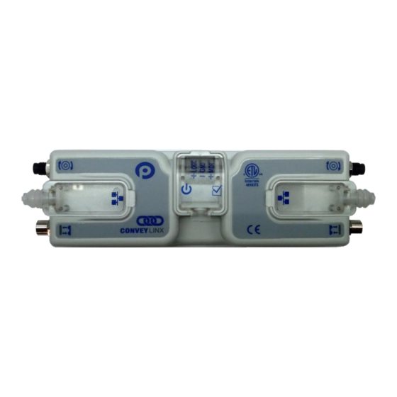
Page 17: Conveylinx-Ai2 Module Hardware Overview
Please refer to Appendix A – Module Dimensions page 97 for module dimensions and mounting details. The ConveyLinx-Ai2 module is a controller for up to 2 Motorized Drive Roller (MDR) conveyor zones. Each ConveyLinx-Ai2 provides connection points for 2 MDR units with their corresponding 2 photo-sensors as well as upstream and downstream network and discreet interconnections to form a complete control system for zoned MDR conveyors. -
Page 18: Hardware Connections
ConveyLinx-Ai2 User’s Guide The “left” and “right” naming convention for the module ports is based upon facing the module as shown and is not to be confused with direction of product flow on the conveyor. Product flow will be designated as “upstream” and “downstream”... -
Page 19: Sensor Left And Sensor Right Ports
IGHT ORTS Each sensor port is a standard M8 Female receptacle with the following pin-out: FIGURE 5 – CONVEYLINX-AI2 FEMALE SENSOR PORT AND MATING SENSOR’S MALE CONNECTOR FIGURE 4–CONVEYLINX SENSOR PORT DIAGRAM The signals are defined by the following chart:... -
Page 20: Aux I/O Pin 2 As Output
ConveyLinx-Ai2 User’s Guide FIGURE 6 - AUX I/O PIN 2 INPUT CONNECTION DIAGRAM Because the auto-sensing circuit requires a nominal voltage in order to operate, there will be some small amount of leakage current possible between Pin 2 and Pin 3 (GND). Please use caution if you connect a load between Pin 2 and Pin 3. -
Page 21: Ethernet Left And Ethernet Right Ports
RJ-45 connectors on the Ethernet cables. Each module is shipped with 3 shrouds. FIGURE 8 – CONVEYLINX-AI2 WITH LEFT & RIGHT ETHERNET CABLES (COVERS REMOVED) FIGURE 9 - ETHERNET CABLES CONNECTED WITH COVERS ATTACHED... - Page 22 ConveyLinx-Ai2 User’s Guide IP54 protective shroud requires a special tool to properly install the shroud onto the RJ-45 connector. Figure 10 shows Phoenix Contact item 2891547 FL IP 54 Assembly Tool. This tool must be purchased separately FIGURE 10 - PHOENIX CONTACT ETHERNET...
-
Page 23: Power Connections
Hardware Connections OWER ONNECTIONS IP54 I NSTALLATION Item 17 as depicted in Figure 2 may be unattached to the module when shipped and are included in the module’s shipping box. These items are used to maintain an IP54 installation of the power and Ethernet wiring. Power wires are fed through the protective shroud (Item 17). - Page 24 ConveyLinx-Ai2 User’s Guide FIGURE 15 - CONNECTION FOR SINGLE MDR AND LOGIC POWER SUPPLY FIGURE 16 - TYPICAL CONNECTION FOR SEPARATE MDR AND LOGIC POWER SUPPLIES Publication ERSC-1006 Rev 1.4 – October 2017...
-
Page 25: Power Supply Common Grounding
Hardware Connections OWER UPPLY OMMON ROUNDING Whether logic and MDR are powered together or separately; the DC common (“-“) connections on all power supplies should be connected together. One of the power supplies should have its DC common connected to ground. -
Page 27: Connections For Linear Conveyor
MDR’s and photo-sensors connected in the proper way for expected operational results. In general, each ConveyLinx-Ai2 module detects which Sensor ports have a device connected and will use this to determine its specific configuration once it has been instructed to self-configure by the Auto-Configuration Procedure. -
Page 28: Example 2 - Single Zone Controller
INGLE ONTROLLER In this case the ConveyLinx-Ai2 module will control 2 MDR’s in tandem and operate as a single zone with a single photo-sensor connected to either the Left or Right port. This configuration is typical for belted zones used particularly on inclined conveyors which require the added torque of a second MDR to accommodate the conveying load. -
Page 29: Invalid Configuration Examples
In these cases the module will try to act as a Single zone conveyor control, but the MDR’s are not plugged into same Left/Right port group as the photo-sensors. In these cases the ConveyLinx-Ai2 will try to act as a two-zone conveyor control but only one MDR is connected. These invalid configurations will not cause the Auto-Configuration function to fail. The user will only experience incorrect operation and/or unexpected results. -
Page 30: Motor Direction Definition
IRECTION EFINITION The ConveyLinx-Ai2 module uses a Clock-Wise (CW) and Counter Clock-Wise (CCW) motor rotation definition. The reference for this distinction is based upon viewing the MDR from the cable exit end of the roller as depicted below in Figure 19. -
Page 31: Status Indicators
Activity LEDs are multi-coloured and context sensitive. The following chart indicates the various meanings of all ConveyLinx-Ai2 LED indicators. Please refer to Figure 2 on page 17 for the item number locations on the module. By definition Blinking is approximately ½ second on/off cycle and Flashing is approximately ¼ second on/off cycle. -
Page 32: Sensors
ConveyLinx-Ai2 User’s Guide ENSORS Indicator Item LED State Description Solid Amber ConveyLinx Ai2 is booting up Solid Green Sensor Input energized Sensors 4 & 5 Solid Red Sensor health signal Blinking Red Zone Jam or missing sensor Flashing Red Network Stop Condition... -
Page 33: Auto-Configuration Of Linear Conveyor
Auto-Configuration of Linear Conveyor ONFIGURATION OF INEAR ONVEYOR The purpose of Auto-Configuration for networked ConveyLinx controls is to provide a simple and easy procedure for linear conveyor system commissioning. The Auto-Configuration of Linear Conveyor feature of ConveyLinx requires the use of the EasyRoll on a PC connected to the most upstream module of the linear network. INEAR ONVEYOR EFINITION... -
Page 34: Installing Easyroll Tool On Your Pc
For the purposes of ConveyLinx; the AAA.BBB.CCC portion of the I.P. address taken together is defined as the Subnet. The DDD value of the address is defined as the Node. For example; if a ConveyLinx-Ai2 has an I.P. address of “192.168.25.20” then its Subnet address is “192.168.25” and its Node is “20”... - Page 35 FIGURE 21 - IP ADDRESSES BEFORE AUTO-CONFIGURATION FIGURE 22 - IP ADDRESSES AFTER AUTO-CONFIGURATION The Auto-Configuration Procedure will assign Nodes up to and including Node 240. Therefore each Subnet is limited to 220 ConveyLinx-Ai2 Nodes. Publication ERSC-1006 Rev 1.4 – October 2017...
-
Page 36: Connecting Your Pc To Conveylinx Network
ConveyLinx-Ai2 User’s Guide ONNECTING ONVEY ETWORK Using an Ethernet cable, connect your PC’s Ethernet port to the Auto-Configuration Master as shown below in Figure 23 FIGURE 23 - INITIAL PC CONNECTION TO CONVEYLINX SUBNET It is highly recommended to connect the PC directly to the ConveyLinx network. Avoid trying to connect via Ethernet switches or wireless router/switches. - Page 37 Failure to meet these conditions will produce unexpected results. Please note that number of modules on a single Subnet is limited to 220. FIGURE 24 - DISCOVER PROCEDURE ON CONVEYLINX-AI2 MODULES Publication ERSC-1006 Rev 1.4 – October 2017...
- Page 38 ConveyLinx-Ai2 User’s Guide FIGURE 25 – TOPOLOGY VIEW AND INITIATING AUTO-CONFIGURE FROM THE SELECTED NODE Note that the detail information in the topology view for each module is shown in RED when the module is un- configured. You can also select the module graphic from the topology view and right click to show the context menu and initiate the Auto-Configuration from there as shown in Figure 26.
- Page 39 Auto-Configuration of Linear Conveyor FIGURE 26 - AUTO-CONFIGURE BY SELECTING NODE IN THE TREE VIEW The selected node for Auto-Configuration does not have to be the first module that is connected directly to the PC. The module at the other end of the detected line can also be selected as the Auto-Configuration master as shown in Figure 27.
- Page 40 ConveyLinx-Ai2 User’s Guide FIGURE 27 - AUTO-CONFIGURATION FROM THE FARTHEST NODE FROM THE PC Publication ERSC-1006 Rev 1.4 – October 2017...
-
Page 41: Auto Detection Of Opposite Side Module Location
ODULE OCATION The cable connections between Left and Right Ethernet ports can be used in situations where the ConveyLinx-Ai2 has to be mounted in the conveyor’s opposite side frame. If properly connected, the Auto-Configure routine will detect this and configure the conveyor flow properly. Figure 28 shows an example of opposite side location detection. - Page 42 ConveyLinx-Ai2 User’s Guide FIGURE 29 - AUTO-CONFIGURATION SUCCESS If all Module Status LED’s are blinking green; then to fully verify configuration is to place a single load onto the most upstream zone and see that it conveys to the discharge zone. If it does, then the Auto-Configuration is successful.
-
Page 43: Trouble-Shooting Failed Auto-Configuration
• Verify that there are no Ethernet Switches or PC’s connected between ConveyLinx-Ai2 modules. The Auto Configuration procedure will abort if a non- ConveyLinx device is detected along the path before reaching the last node. Status LED blinking or... -
Page 44: Default Singulation Release Zpa Mode
ConveyLinx-Ai2 User’s Guide ZPA M EFAULT INGULATION ELEASE Loads will normally convey from upstream zone to downstream zone in singulation release fashion. A load reaching last zone photo-sensor will cause last zone motor to continue to run to discharge load to next conveyor or position. -
Page 45: Default Flex Zone Recognition Feature
ECOGNITION EATURE ConveyLinx-Ai2 modules will automatically detect that a given carton is longer than one zone length and automatically adjust accumulation control so that the longer carton occupies two logical zones and will keep the next upstream carton from conveying into the longer carton. Flex Zone mode operates for both singulation and train release modes. -
Page 46: Jam Conditions
After the Sensor Jam occurs and the sensor remains blocked; the ConveyLinx-Ai2 will attempt to self-clear the Sensor Jam condition. First, the ConveyLinx-Ai2 will run the affected zone’s motor in reverse for up to 1 second in order to clear the blocked sensor. If the sensor is still blocked after this first reversing attempt, it will repeat this motion 2 more times. -
Page 47: Network Fault
OLTAGE AULT In instances when the ConveyLinx-Ai2 module detects that its supply voltage has dipped below 18VDC; the ConveyLinx-Ai2 will place its configured zone or zones into accumulation mode. The ConveyLinx-Ai2 will keep this state until it has detected that its input voltage has risen to at least 21VDC. -
Page 48: Automatic Module Replacement
EasyRoll software. The ConveyLinx-Ai2 firmware uses this feature to allow for easy module replacement so that the entire linear conveyor does not have to be re-configured in order to replace a single module. - Page 49 Auto-Configuration of Linear Conveyor FIGURE 33 - TOPOLOGY VIEW AND REPLACING THE SELECTED NODE You can also replace a module by selecting the module graphic directly in the topology view, right click to display the context menu, and select “Replace this Node” as shown in Figure 34. Publication ERSC-1006 Rev 1.4 –...
- Page 50 ConveyLinx-Ai2 User’s Guide FIGURE 34 - MODULE REPLACEMENT FROM TOPOLOGY VIEW Publication ERSC-1006 Rev 1.4 – October 2017...
-
Page 51: Module Replacement Using Replacement Button
EPLACEMENT UTTON You can replace a single ConveyLinx-Ai2 module without using EasyRoll by utilizing the Replacement Button located inside the Left Ethernet cable connection compartment. Simply install the replacement module and connect all sensors, motors, network cables, and power connections. The procedure is illustrated below. -
Page 53: Easyroll Software Configuration Tool
Some of the advanced features available with EasyRoll are: • Firmware Upgrade utility for one or a group of ConveyLinx-Ai2’s. Network Services Discover utility used to find all ConveyLinx-Ai2’s on a network and manually set their I.P. • addresses. •... -
Page 54: Options For Configuring Your Pc's Ip Address
DDRESS Note that your PC’s I.P. address does not have to be in the same subnet as your ConveyLinx-Ai2 modules in order to perform the Auto Configuration procedure with EasyRoll as described in the previous section. However, your PC’s I.P. address and/or subnet mask has to be properly set in order to read and change ConveyLinx-Ai2 module’s parameters and settings. -
Page 55: Manual I.p. Address Configuration Methods
ONFIGURATION ASTER For either manual method of I.P. address configuration, you must access the I.P. address information of the Auto- Configuration Master ConveyLinx-Ai2 on your network by using EasyRoll. TARTING PPLICATION If you followed the default installation setting when you installed EasyRoll; the program should be selected from “Start –... -
Page 56: Using The Network Services Utility
One of the features of EasyRoll is that it has a utility called Network Services Discover that allows your PC to go and find any ConveyLinx-Ai2 modules that may be physically connected to you network regardless of the I.P. address settings of your PC or the I.P. -
Page 57: Method 2 - Change Pc To Match Auto-Config Master
EasyRoll Software Configuration Tool After clicking the Network Services tab, you will see the screen you will use to both “discover” the ConveyLinx-Ai2’s that can be found as well as select a specific ConveyLinx-Ai2 in which to modify its I.P. address settings. -
Page 58: Method 3 - Change Auto-Config Master I
Configuration Master’s I.P. address has been changed. You must perform the Auto Configuration Procedure again so that all downstream ConveyLinx-Ai2’s will have their I.P. address updated to match the Auto Configuration Master’s new Subnet. Publication ERSC-1006 Rev 1.4 – October 2017... -
Page 59: Easyroll Main Screen
EasyRoll Software Configuration Tool CREEN Assuming you have either changed your PC’s configuration or changed the Auto Configuration Master’s configuration as described above; you should now be able to use the EasyRoll main screen to view your system’s status and change operational parameters. If you have followed the above example, simply closing the ConveyLinx Advanced Dialog will show the main screen. -
Page 60: Connecting To Conveylinx
ConveyLinx-Ai2 User’s Guide Item Description Network IP – This is where you enter the Subnet of the particular ConveyLinx network you wish to connect Node No. – This is where you enter a range of Nodes in which to connect. Entering values here will cause the “Refresh”... -
Page 61: Node Navigation
“Node No.” area and its information is displayed on the main screen; clicking the “Blink&Wink” switch will signal the selected ConveyLinx-Ai2 to blink on and off all of its LED indicators. Click the “Blink&Wink” switch again to turn this off. -
Page 62: Module Diagnostic Window
ConveyLinx-Ai2 User’s Guide ODULE IAGNOSTIC INDOW By clicking the image of the ConveyLinx-Ai2 module in the upper right of the main screen will open the Module Diagnostic Window. Click the image in the upper right to open the Module Diagnostic Window and... - Page 63 EasyRoll Software Configuration Tool One very useful feature of the Module Diagnostic Window is that you can mouse-over the image of each roller and a pop-up will display the pertinent motor parameters as well as the part number and serial number of the connected roller as shown in Figure 37.
-
Page 64: Upstream / Downstream Zone Configuration
ConveyLinx-Ai2 User’s Guide PSTREAM OWNSTREAM ONFIGURATION Once you have selected the particular Node you wish to view and/or modify, you can go to the particular settings. Selecting the pull down box for “ZPA Mode” will show the available selections. Singulation is the default configuration. -
Page 65: Zpa Mode Selections
EasyRoll Software Configuration Tool ZPA M ELECTIONS Singulation mode is the default configuration for all zones upon the completion of the Auto Configuration Procedure. Please refer to section Default Singulation Release ZPA Mode on page 44 for description. The following sections describe the ZPA modes available via EasyRoll. -
Page 66: T-Bone Configuration
ConveyLinx-Ai2 User’s Guide Timer expires; the discharge zone will release and the train of cartons in all 10 upstream zones will again move simultaneously forward. When you select “Gap Train” from the “ZPA Mode” drop-down box; the “Gap Timer” data entry box and “Set”... - Page 67 1. Sending and Accepting zones can be on the same ConveyLinx-Ai2 2. Sending and Accepting zones can be on separate ConveyLinx-Ai2’s. Figure 40 and Figure 41 depict two ways to connect the MDR’s and photo-sensors to ConveyLinx-Ai2 modules to result in a valid T-Bone configuration.
-
Page 68: Ignore Jam Settings
ConveyLinx-Ai2 User’s Guide GNORE ETTINGS Any individual zone or group of zones can be configured to ignore the auto reset time delay for either or both of the detected jam conditions. These jam conditions are described in section Jam Condition on page 46. Selecting either of these options will not eliminate the detection of the particular jam condition;... -
Page 69: Mdr Settings
Clicking “Set All” will download the selected setting to the Left Zones of all ConveyLinx-Ai2’s entered in the range of Nodes at the top of the main screen in the “Node No:” boxes. If for example the “Node No.”... - Page 70 Standard Dynamic braking - MDR power circuit in ConveyLinx-Ai2 is internally connected during motor stop sequence to provide backward energy to bring rotor to a stop. When ConveyLinx-Ai2 has detected that the motor has stopped; all Normal winding current is shut off from the MDR. This is the MDR industry standard...
-
Page 71: Speed
The Speed setting value is in meters per second (m/s). The Senergy-Ai2 motor roller contains data as to its particular gear reduction ratio and roller diameter that is readable by the ConveyLinx-Ai2 module. EasyRoll then uses this information to indicate whether the speed you enter is valid for the connected roller. -
Page 72: Motor Direction
HEAD EATURE The Look Ahead feature configures the ConveyLinx-Ai2 logic to “look ahead” to its next downstream zone and if it is occupied when a load is entering its zone, ConveyLinx-Ai2 will dynamically adjust the MDR to the selected speed. - Page 73 FIGURE 43 - LOOK AHEAD ENABLED As shown in Figure 43, when a carton arrives at Zone C’s photo-sensor, Zone B’s ConveyLinx-Ai2 will automatically adjust the speed of Zone B to the configured Look Ahead speed.
- Page 74 ConveyLinx-Ai2 User’s Guide Click the checkbox to enable the Look Ahead feature for the selected Node. Clicking the “Set” buttons will download the setting to the respective zone on the selected Node. The value entered for the slowdown speed is in percent of the Node’s speed as...
- Page 75 1 seconds to 20 seconds. The Auto Clear Timer is the amount of times that ConveyLinx-Ai2 waits before trying to clear a jam. After a Jam does occur, it’s now possible to set a time to wait before attempting to clear the current jam and trying again.
- Page 76 ConveyLinx-Ai2 User’s Guide Clicking any of the “Set” buttons for either Jam or Run After timers will download the entered setting to the respective zone on the selected Node. (Refer to the EasyRoll Tool Pop-Up Dialogue for detailed information regarding the...
-
Page 77: Upgrade
The Upgrade tab screen gives access to the ConveyLinx-Ai2 firmware utility. Over time, enhancements and features may be added to the ConveyLinx family of products. These features and enhancements are typically made available to customers in the form of firmware upgrade files that need to be uploaded to your ConveyLinx-Ai2 modules. - Page 78 ConveyLinx-Ai2 User’s Guide With the “Open” dialog displayed, navigate to the location on your PC where you placed the firmware upgrade file you received. Select the file and click “Open”. In this example, we clicked “Upload ALL” so the selected firmware upgrade file will be sent to all 6 Nodes.
-
Page 79: Connections
Advanced Dialog window. ONNECTIONS The Connections utility uses EasyRoll to instruct a given ConveyLinx-Ai2 to make a logical connection to another ConveyLinx-Ai2 that it otherwise would not have made during the Auto-Configuration Procedure. For applications where you have more than one ConveyLinx Subnet, this would be the way to logically connect the most downstream Node of one Subnet to the most upstream Node of another Subnet. - Page 80 ConveyLinx-Ai2 User’s Guide By simply connecting a crossover Ethernet cable between these two boundary Nodes and then using EasyRoll establish the “logical” connection between the two Subnets; you can achieve seamless flow between the two networks. This is shown in Figure 45.
- Page 81 EasyRoll Software Configuration Tool Configuring Node at 192.168.27.25 From the main screen, first enter the correct Subnet into the “Network IP” boxes and the correct Node you want to connect. In this case we know that xxx.xxx.xxx.25 is Node 6 for this particular Subnet. Invoke the ConveyLinx Advanced Dialog and select the Connections tab.
- Page 82 ConveyLinx-Ai2 User’s Guide We want to change the Downstream flow to I.P. address 192.168.25.20 which is the next downstream Node. Click the IP Address button and enter the correct I.P. address value and click the “Apply” button. Please note that this will take approximately 20 seconds for the module to accept the change and then the module will automatically restart.
- Page 83 EasyRoll Software Configuration Tool Configuring Node at 192.168.25.20 From the main screen, first enter the correct Subnet into the “Network IP” boxes and the correct Node you want to connect. In this case we know that xxx.xxx.xxx.20 is Node 1 for this particular Subnet. Invoke the ConveyLinx Advanced Dialog and select the Connections tab.
- Page 84 ConveyLinx-Ai2 User’s Guide We want to tell this Node to accept loads from I.P. address 192.168.27.25 which is the next upstream Node. Click the IP Address button and enter the correct I.P. address value and click the “Apply” button. Please note that this will take approximately 20 seconds for the module to accept the change and then the module will automatically restart.
-
Page 85: Network Services
The Network Services screen is used to both explore any networks reachable by the PC for any ConveyLinx-Ai2 modules and it is used to set the I.P. address of a selected ConveyLinx-Ai2. Refer to section Using the Network Services Utility on page 56 for details. - Page 86 ConveyLinx-Ai2 User’s Guide Depending on how the module is configured, you can independently select which of these functions you want to reside on which of the 2 sensor port’s Pin 2 signals. OWNSTREAM Please note that by default and without any intervention, the most downstream zone will always try to discharge product.
- Page 87 EasyRoll Software Configuration Tool Assuming the most downstream zone is connected to the right side of the module; we set the Right Aux I/O Pin 2 to “Accumulate” from the drop down box and make sure we click the “DN” arrow to indicate that the Right Pin 2 signal is to be associated with the Downstream Zone.
- Page 88 ConveyLinx-Ai2 User’s Guide PSTREAM Similarly, by default and without any intervention, the most upstream zone will never turn on to accept new product. To cause the most upstream zone to run to accept an item with a wired signal, you need to utilize the Aux I/O Pin 2 for the upstream zone as a Wake up input.
- Page 89 EasyRoll Software Configuration Tool CCUMULATE NTERMEDIATE By default and without intervention; all zones in between the most upstream and most downstream zones always try to convey items downstream as long as the next downstream zone is clear. To cause an intermediate zone to accumulate based upon a wired signal, you need to utilize the Aux I/O Pin 2 signal for the zone in questions as an Accumulate input.
- Page 90 ConveyLinx-Ai2 User’s Guide NTERFACE A special case of the accumulate signal for the most downstream zone is referred to as Lane Full Interface. When Lane Full Interface is used on the most downstream zone; the input signal is treated with a block and clear timer such that when the signal is energized, the signal must remain energized for the “block”...
- Page 91 In applications where the equipment feeding the most upstream zone of ConveyLinx-Ai2 controlled conveyor requires a handshake interlock to know when the most upstream zone of the ConveyLinx-Ai2 controlled conveyor is empty and ready to accept a new item, this can be achieved by utilizing both the Left and Right Aux I/O Pin signals.
- Page 92 ANDSHAKE NTERLOCK In applications where the equipment accepting product from the most downstream zone of ConveyLinx-Ai2 controlled conveyor requires a handshake interlock to know when the most downstream zone of the ConveyLinx- Ai2 controlled conveyor is occupied and ready to discharge the item, this can be achieved by utilizing both the Left and Right Aux I/O Pin signals.
- Page 93 EasyRoll Software Configuration Tool I/O P NVERTING THE IGNALS On this dialog, you can also invert the meaning of the electrical signal by checking the “Invert” box for either or both Pins. In this example, because we have the Invert box checked for both Pin signals, their respective functions will be activated when their signal is electrically OFF.
-
Page 94: Flex Zone
ConveyLinx-Ai2 User’s Guide ConveyLinx-Ai2 modules will automatically detect that a given carton is longer than one zone length and automatically adjust accumulation control so that the longer carton occupies two logical zones and will keep the next upstream carton from conveying into the longer carton. . This tab allows you to either enable or disable the feature. - Page 95 EasyRoll Software Configuration Tool Publication ERSC-1006 Rev 1.4 – October 2017...
-
Page 97: Appendixa - Module Dimensions
Appendix A – Module Dimensions A – M PPENDIX ODULE IMENSIONS Dimensions in mm Publication ERSC-1006 Rev 1.4 – October 2017... -
Page 99: Appendix B - Iox-2Breakout Module
The IOX-2breakout module provides a convenient plug and play means to separate the zone sensor and Aux I/O signals on the ConveyLinx-Ai2 module’s sensor port. The IOX-2 utilizes M8 style connection headers so you can connect your M8 style zone sensor as well as M8 style cable (or additional sensor) for access to the Aux I/O Pin 2 signal. - Page 100 ConveyLinx-Ai2 User’s Guide FIGURE 48 - WAKE UP AND LANE FULL INTERFACE SENSORS CONNECTED TO WIRE TERMINALS FIGURE 49 - WAKE UP AND LANE FULL INTERFACE SIGNALS AS DEVICE CONTACTS Publication ERSC-1006 Rev 1.4 – October 2017...
- Page 101 Appendix B - IOX-2Breakout Module FIGURE 50 - UPSTREAM WAKE UP WITH PRODUCT ON ZONE OUTPUT EXAMPLE FIGURE 51 - DOWNSTREAM LANE FULL INTERFACE WITH PRODUCT ON ZONE EXAMPLE Publication ERSC-1006 Rev 1.4 – October 2017...
- Page 102 ConveyLinx-Ai2 User’s Guide FIGURE 52 - AUX M8 PORT USED AS OUTPUT FIGURE 53 - USING WIRED TERMINALS FOR SENSOR PORT AUX I/O CONFIGURED AS AN OUTPUT Publication ERSC-1006 Rev 1.4 – October 2017...
- Page 103 Appendix B - IOX-2Breakout Module FIGURE 54 - TYPICAL CONNECTION WIRING DIAGRAMS FIGURE 55 - ELECTRICAL SCHEMATIC OF IOX-2 MODULE Publication ERSC-1006 Rev 1.4 – October 2017...
-
Page 105: Appendix C-Configuring Pc For Ethernet Subnets
Appendix C–Configuring PC for Ethernet Subnets C–C PPENDIX ONFIGURING THERNET UBNETS , IP A ONVEY DDRESSES UBNETS In order to connect to a ConveyLinx network and/or utilize and manage a multiple subnet ConveyLinx conveyor installation; a certain level of Ethernet I.P. addressing knowledge is required. This reference provides some background information and a quick guide for setting up your PC to be able to take full advantage of ConveyLinx and EasyRoll. -
Page 106: Configuration Example
ConveyLinx-Ai2 User’s Guide FIGURE 56 - AVAILABLE SUBNETS PER TYPICAL SUBNET MASK VALUES As you can see, by simply manipulating the Subnet Mask values, you can configure your PC to see multiple ConveyLinx networks. ONFIGURATION XAMPLE Your PC’s I.P. address is used by an Ethernet network to identify the PC on a network. For most office networks, the I.P. - Page 107 FIGURE 57 - IP ADDRESS CONFIGURATION EXAMPLE Please Note: The ConveyLinx IP address structure is designed such that all ConveyLinx-Ai2’s last octet (DDD) of their address is greater than or equal to 20 and less than or equal to 240. This leaves 36 spare valid addresses (256 –...
-
Page 109: Appendixd - Application Examples
The most common use of the Extension mode configuration available from the Connections tab selection is for a powered lift gate. Figure 58 shows a typical powered lift gate example. In this example the ConveyLinx-Ai2 on the lifting or gate portion of conveyor has 2 MDR’s and no photo-sensors. Normal operation when the gate is down is for the MDR’s on the gate to run when its immediate downstream zone runs so as to create “one long logical... - Page 110 ConveyLinx-Ai2 User’s Guide Configure Node 192.168.25.23 From the main screen, enter the correct Subnet and then select the proper Node within the Subnet. In this case it is Node 4 of Subnet 192.168.25. Invoke the ConveyLinxAdvanced Dialog. Note that Node 4’s information is displayed in the center and that it is greyed out.
- Page 111 Appendix D – Application Examples Configure Node 192.168.25.25 From the main screen, enter the correct Subnet and then select the proper Node within the Subnet. In this case it is Node 6 of Subnet 192.168.25. Invoke the ConveyLinxAdvanced Dialog. Note that Node 6’s information is displayed in the center and that it is greyed out.
- Page 112 85. For the lift gate example, the sensor device would have to be wired to Pin 2 and be selected to give a signal when the gate is lifted to tell the upstream ConveyLinx-Ai2 to accumulate. When the gate is down, the device signal should be removed from the ConveyLinx-Ai2 to instruct its zone to convey as normal.
-
Page 113: Appendixe - Power Supply Loading
Please note that the current values shown are per Motor Port, so if both Motor Ports are being used on a given ConveyLinx-Ai2 module, the current load seen by the power supply for that module will be double the value shown. -
Page 115: Notes
OTES Publication ERSC-1006 Rev 1.4 – October 2017... - Page 116 Publication ERSC-1006 Rev 1.4 – October 2017...
Need help?
Do you have a question about the ConveyLinx-Ai2 and is the answer not in the manual?
Questions and answers