Table of Contents
Advertisement
Quick Links
Advertisement
Table of Contents

Related Manuals for Pulseroller EZ-Qube


Summary of Contents for Pulseroller EZ-Qube
- Page 1 EZ-Qube Reference Manual Version 4.1 — 23 August 2024 Copyright © 2024 PULSEROLLER...
- Page 2 Har e Hardwar dware e ..........................................................11 11 2.1. Identifying Module Components ......................13 2.1.1. EZ-Qube .............................. 14 2.1.2. EZ-Qube-HTBF ..........................16 2.1.3. EZ-Qube-W ............................18 2.2. Mounting Dimensions ........................... 20 2.3. Mounting Considerations ........................22 2.4. Power Connector ............................25 2.5.
-
Page 3: Table Of Contents
5. 5. EZ-Qub EZ-Qube-W & EZ-Qub e-W & EZ-Qube-W e-W-Ai Bluet -Ai Blueto o oth Set-Up oth Set-Up....................................90 5.1. Motor & Holding Brake Settings......................92 5.2. Speed Settings ............................94 5.3. Input / Output Signal Settings ......................95 6. - Page 4 EZ-Qub EZ-Qube Con e Contr tro o ll ller er The Pulseroller EZ-Qub EZ-Qube e model controllers provide P P er erf f orman ormanc c e Driv e Drive Con e Contr tro o l l for Senergy motor rollers and gear drive units. Here are some features that are in addition to our Simple Drive Control models: •...
- Page 5 PULSEROLLER EZ-Qube Reference Manual - 4.1_en Runni ● PN SPEE ERRO EZ-Qub EZ-Qube-P-J e-P-J ✘ ✘ ✘ Outpu 1510-6040 ● No COMM Requi ● PN SPEE ERRO Outpu ✔ ✔ ✔ ✔ ✔ ✔ Qube- e-HTBF HTBF-P -P ● 1510-4110...
- Page 6 PULSEROLLER EZ-Qube Reference Manual - 4.1_en ● Blueto Interf ● EZ-Qub EZ-Qube-W e-W- - Sener ✔ ✔ ✘ ✘ Ai Ai Ai mo 1521-0060 contro ● Match EZ-24 Footp Page 6 of 119...
- Page 7 PULSEROLLER EZ-Qube Reference Manual - 4.1_en 1.1. 1.1. Ab About This Man out This Manual EZ-Qub EZ-Qube Con e Contr tro o ll ller er About This Man out This Manual Symb Symbo o l Con l Conv v en...
- Page 8 PULSEROLLER EZ-Qube Reference Manual - 4.1_en and requirements associated with any particular installation, Pulseroller does not assume responsibility or liability (to include intellectual property liability) for actual use based on the examples shown in this publication Reproduction of the contents of this manual, in whole or in part, without written...
- Page 9 MDR industry as a simple description of the particular socket style used on EZ-Qube Module hardware Light Emitting Diode – In the context of this document, LED’s are used on the EZ-Qube Module to provide visual indication of module status Motorized Drive Roller or Motor Driven Roller –...
- Page 10 Mode of performance that provides the highest speed for the selected gear reduction Sener ergy gy ECO option of the PulseRoller Senergy brand motor roller and gear drive units Mode of performance that provides the highest torque for the selected gear reduction Sener ergy...
- Page 11 PULSEROLLER EZ-Qube Reference Manual - 4.1_en 2. 2. Mo Modul dule Har e Hardwar dware e Modul dule Har e Hardwar dware e EZ-Qub EZ-Qube Mo e Modul dule e s s are designed to be installed and integrated into the conveyor’s mechanical side frame assembly.
- Page 12 PULSEROLLER EZ-Qube Reference Manual - 4.1_en Id Iden entifyin tifying EZ-Qub g EZ-Qube Mo e Modul dule Comp e Compon onen ents ts Moun Mountin ting Dim g Dimensions ensions Motor P or Por orts ts LED Status In Status Indic...
- Page 13 PULSEROLLER EZ-Qube Reference Manual - 4.1_en 2.1. 2.1. Id Iden entifyin tifying Mo g Modul dule Comp e Compon onen ents ts Modul dule Har e Hardwar dware e Id Iden entifyin tifying Mo g Modul dule Comp e Compon...
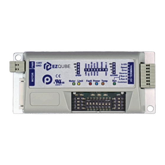
- Page 14 PULSEROLLER EZ-Qube Reference Manual - 4.1_en 2.1.1. 2.1.1. EZ-Qub EZ-Qube e Modul dule Har e Hardwar dware e Id Iden entifyin tifying Mo g Modul dule Comp e Compon onen ents ts EZ-Qub EZ-Qube e ● ● EZ-Qub EZ-Qube-P ● ● EZ-Qub EZ-Qube-N ●...
- Page 15 PULSEROLLER EZ-Qube Reference Manual - 4.1_en Motor Speed Selection 4 Position DIP Switch Configuration 8 Position DIP Switch Motor Accel/Decel 4 Position DIP Switch DIP Switch and LED Hinged Clear Protective Cover Module Status LEDs Page 15 of 119...
- Page 16 PULSEROLLER EZ-Qube Reference Manual - 4.1_en 2.1.2. 2.1.2. EZ-Qub EZ-Qube-HTBF e-HTBF Modul dule Har e Hardwar dware e Id Iden entifyin tifying Mo g Modul dule Comp e Compon onen ents ts EZ-Qub EZ-Qube- e-HTBF HTBF ● ● EZ-Qub EZ-Qube- e-HTBF HTBF-P -P ●...
- Page 17 PULSEROLLER EZ-Qube Reference Manual - 4.1_en DIP Switch and LED Hinged Clear Protective Cover Module Status LEDs Page 17 of 119...
- Page 18 PULSEROLLER EZ-Qube Reference Manual - 4.1_en 2.1.3. 2.1.3. EZ-Qub EZ-Qube-W Modul dule Har e Hardwar dware e Id Iden entifyin tifying Mo g Modul dule Comp e Compon onen ents ts EZ-Qub EZ-Qube-W ● ● EZ-Qub EZ-Qube-W It Item Description...
- Page 19 PULSEROLLER EZ-Qube Reference Manual - 4.1_en ● ● EZ-Qub EZ-Qube-W e-W-Ai It Item Description scription Removable 24VDC Power Connector Terminal Block Senergy-Ai Motor Port – 4-pin M8 style header for MDR/PGD connection Removable I/O Terminal Block Module Status LEDs Page 19 of 119...
- Page 20 PULSEROLLER EZ-Qube Reference Manual - 4.1_en 2.2. 2.2. Moun Mountin ting Dim g Dimensions ensions Modul dule Har e Hardwar dware e Moun Mountin ting Dim g Dimensions ensions ● ● EZ-Qub EZ-Qube-P ● ● EZ-Qub EZ-Qube-N ● ● EZ-Qub...
- Page 21 PULSEROLLER EZ-Qube Reference Manual - 4.1_en ● ● EZ-Qub EZ-Qube- e-HTBF HTBF-P -P ● ● EZ-Qub EZ-Qube- e-HTBF HTBF-N ● ● EZ-Qub EZ-Qube-W ● ● EZ-Qub EZ-Qube-W e-W-Ai Page 21 of 119...
- Page 22 Considerations erations EZ-Qube module must be mounted with its long side parallel to the conveyor frame and with its heat sink plate in contact with the conveyor frame. Attach module to frame using fasteners through the 2 mounting holes on the module through matching holes drilled into conveyor frame.
- Page 23 PULSEROLLER EZ-Qube Reference Manual - 4.1_en Page 23 of 119...
- Page 24 PULSEROLLER EZ-Qube Reference Manual - 4.1_en Page 24 of 119...
- Page 25 PULSEROLLER EZ-Qube Reference Manual - 4.1_en 2.4. 2.4. P P o o w w er Conn er Conne e ct ctor or Modul dule Har e Hardwar dware e P P o o w w er Conn er Conne e ct ctor or...
- Page 26 All EZ-Qube e EX EXCEPT CEPT EZ-Qub EZ-Qube-W e-W-Ai The EZ-Qube Module motor port is a 9 pin JST Style connector that accommodates Pulseroller Senergy motor rollers and PGD units. Description scription Vcc – Hall Effect Sensor Power Motor Winding U...
- Page 27 Please note the JST connector is keyed so you cannot plug it in upside down EZ-Qub EZ-Qube-W e-W-Ai The EZ-Qube-W-Ai motor port is a 4 pin M8 Male Style connector that accommodates Pulseroller Senergy-Ai motor rollers and PGD units. Description scription...
- Page 28 PULSEROLLER EZ-Qube Reference Manual - 4.1_en 2.6. 2.6. I/O Conn I/O Conne e ct ctor or Modul dule Har e Hardwar dware e I/O Conn I/O Conne e ct ctor or Wire terminals on all removable connectors are “cage-clamp” style...
- Page 29 PULSEROLLER EZ-Qube Reference Manual - 4.1_en Accepts +24V or 0V input for run at speed control (see section Run A Run A Input and Run B Inputs) Accepts +24V or 0V input for run at speed control (see section Run A...
- Page 30 PULSEROLLER EZ-Qube Reference Manual - 4.1_en 2.7. 2.7. Insp Inspe e ction an ction and Cl d Cle e anin aning g Modul dule Har e Hardwar dware e Insp Inspe e ction an ction and Cl d Cle e anin...
- Page 31 PULSEROLLER EZ-Qube Reference Manual - 4.1_en 2.8. 2.8. T T e e chnic chnical Sp al Spe e cific cifications ations Modul dule Har e Hardwar dware e T T e e chnic chnical Sp al Spe e cific cifications...
- Page 32 PULSEROLLER EZ-Qube Reference Manual - 4.1_en Motor PWM Frequency 33.3 kHz +/- 0.1% Digital Input Minimum ON 1.5 mA Current Digital Input Maximum 0.4 mA OFF Current Initialization Time <= 20 msec from power on Motor Start Response <= 5 msec Storage Temperature -40ºC to 85º...
- Page 33 Ord d er Co er Cod d e e Ord d er T er Typ ype e Description scription EZ-Qube 24V Performance Drive Module, Standard JST Motor Port, Auto Sensing PNP/NPN Inputs, NPN Error/Speed Output, Motor 1510-4120 1510-4120 EZ-Qub EZ-Qube- e-HTBF HTBF-N...
- Page 34 PULSEROLLER EZ-Qube Reference Manual - 4.1_en EZ-Qube 24V Performance Drive Module, Ai Technology M8 Motor 1521-0060 1521-0060 EZ-Qub EZ-Qube-W e-W-Ai Port, Bluetooth Interface, Mobile App Selectable PNP/NPN Inputs/ Outputs, Motor Rated Up to 7 Amps in Boost-7 Mode Removable Terminal, 2 Pin, Cage Clamp, EZ-Cube Power Connector...
- Page 35 PULSEROLLER EZ-Qube Reference Manual - 4.1_en 3. 3. Mo Modul dule Wirin e Wiring g Modul dule Wirin e Wiring g P P o o w w er Supp er Suppl l y y Motor Gr or Groun oundin ding Practic...
- Page 36 Suppl l y Re y Requir quirem emen ents ts The power supply for any and all EZ-Qube Module modules should meet the following requirements: • Capable of detecting and properly handling short circuit and overload of its DC power output •...
- Page 37 Suppl l y Sizin y Sizing g The current loading on the power supply for a group of EZ-Qube Modules depends upon the Motor Type selected. Each of the motor types available has an associated rated current that the motor will draw at rated torque and maximum speed. Each motor type also has an associated allowed current draw that is available for a period of time upon the initial starting of the motor.
- Page 38 Improper grounding of MDR and/or Power Supply Common may result in premature MDR and/or EZ-Qube Module module failure. Proper grounding techniques MUST be observed for all applications Page 38 of 119...
- Page 39 EZ-Qube-W and EZ-Qube-W-Ai modules. The PNP and NPN versions of EZ-Qube Module refer to how the ERROR and SPEED OUTPUTS are electrically configured at the factory. NPN or PNP EZ-Qube Module part number designations d d o n...
- Page 40 PULSEROLLER EZ-Qube Reference Manual - 4.1_en 3.3.1. 3.3.1. Sin Singl gle Mo e Modul dule e Modul dule Wirin e Wiring g Run/Re Run/Rev v erse Inputs erse Inputs Singl gle Mo e Modul dule e ● ● EZ-Qub EZ-Qube-P / EZ-Qub...
- Page 41 PULSEROLLER EZ-Qube Reference Manual - 4.1_en ● ● EZ-Qub EZ-Qube-P-J e-P-J ● ● EZ-Qub EZ-Qube-W & EZ-Qub e-W & EZ-Qube-W e-W-Ai w -Ai wh h en Input Input Sele e ct is ct is PNP ● ● EZ-Qub EZ-Qube-W & EZ-Qub e-W &...
- Page 42 PULSEROLLER EZ-Qube Reference Manual - 4.1_en 3.3.2. 3.3.2. Multip Multipl l e Mo e Modul dule e s fr s from Sin om Singl gle Signal e Signal Modul dule Wirin e Wiring g Run/Re Run/Rev v erse Inputs erse Inputs...
- Page 43 PULSEROLLER EZ-Qube Reference Manual - 4.1_en Sour Sourcin cing EZ-Qub g EZ-Qube / Sinkin e / Sinking g PL PLC C Output Output ● ● EZ-Qub EZ-Qube-P-J e-P-J ● ● EZ-Qub EZ-Qube-W & EZ-Qub e-W & EZ-Qube-W e-W-Ai w -Ai wh h en...
- Page 44 PULSEROLLER EZ-Qube Reference Manual - 4.1_en ● ● EZ-Qub EZ-Qube-W & EZ-Qub e-W & EZ-Qube-W e-W-Ai w -Ai wh h en Input Input Sele e ct is ct is NPN Page 44 of 119...
- Page 45 PULSEROLLER EZ-Qube Reference Manual - 4.1_en Page 45 of 119...
- Page 46 PULSEROLLER EZ-Qube Reference Manual - 4.1_en 3.3.3. 3.3.3. Multip Multipl l e Mo e Modul dule e s fr s from In om Individual dividual Signals Signals Modul dule Wirin e Wiring g Run/Re Run/Rev v erse Inputs erse Inputs...
- Page 47 PULSEROLLER EZ-Qube Reference Manual - 4.1_en Sour Sourcin cing EZ-Qub g EZ-Qube / Sinkin e / Sinking g PL PLC C Output Output Page 47 of 119...
- Page 48 PULSEROLLER EZ-Qube Reference Manual - 4.1_en ● ● EZ-Qub EZ-Qube-P-J e-P-J ● ● EZ-Qub EZ-Qube-W & EZ-Qub e-W & EZ-Qube-W e-W-Ai w -Ai wh h en Input Input Sele e ct is ct is PNP Page 48 of 119...
- Page 49 PULSEROLLER EZ-Qube Reference Manual - 4.1_en ● ● EZ-Qub EZ-Qube-W & EZ-Qub e-W & EZ-Qube-W e-W-Ai w -Ai wh h en Input Input Sele e ct is ct is NPN Page 49 of 119...
- Page 50 PULSEROLLER EZ-Qube Reference Manual - 4.1_en 3.4. 3.4. 0-10V Anal 0-10V Analo o g Input g Input Modul dule Wirin e Wiring g 0-10V Anal 0-10V Analo o g Input g Input The Sp Spe e e e d d DIP Switches 1 thru 5 must be properly set for Anal...
- Page 51 PULSEROLLER EZ-Qube Reference Manual - 4.1_en Anal Analo o g Sour g Sourc c e Input e Input Anal Analo o g P g Pot oten entiom tiomet eter er Anal Analo o g P g Pot oten entiom tiomet eter with Minim...
- Page 52 PULSEROLLER EZ-Qube Reference Manual - 4.1_en Here are some resistor values to get some common minimum speeds when the potentiometer is set to 0: Minim Minimum R1 ( R1 (Ω Ω ) ) R2 ( R2 (Ω Ω ) ) Spe e e e d d 1.6k...
- Page 53 PULSEROLLER EZ-Qube Reference Manual - 4.1_en 3.5. 3.5. Err Error Output or Output Modul dule Wirin e Wiring g Error Output or Output The Err Error Output or Output provides a digital signal to indicate various error conditions. This signal coupled with the Err...
- Page 54 PULSEROLLER EZ-Qube Reference Manual - 4.1_en 3.5.1. 3.5.1. PNP V PNP Versions ersions Modul dule Wirin e Wiring g Error Output or Output PNP V V ersions ersions ● ● EZ-Qub EZ-Qube-P ● ● EZ-Qub EZ-Qube-P-MR e-P-MR ● ● EZ-Qub...
- Page 55 Input In this wiring scheme, ANY of the EZ-Qube ERROR ERROR signals will energize the PLC input. Also, if more that one EZ-Qube module has energized its ERROR ERROR signal, the PLC input will be energized. Page 55 of 119...
- Page 56 PULSEROLLER EZ-Qube Reference Manual - 4.1_en Wirin Wiring Multip g Multipl l e e PNP PNP Mo Modul dule e s t s to In o Individual dividual Inputs Inputs Page 56 of 119...
- Page 57 PULSEROLLER EZ-Qube Reference Manual - 4.1_en 3.5.2. 3.5.2. NPN V NPN Versions ersions Modul dule Wirin e Wiring g Error Output or Output NPN V V ersions ersions ● ● EZ-Qub EZ-Qube-N ● ● EZ-Qub EZ-Qube- e-HTBF HTBF-N or Out is set to o NPN ●...
- Page 58 Input In this wiring scheme, ANY of the EZ-Qube ERROR ERROR signals will energize the PLC input. Also, if more that one EZ-Qube module has energized its ERROR ERROR signal, the PLC input will be energized. Page 58 of 119...
- Page 59 PULSEROLLER EZ-Qube Reference Manual - 4.1_en Wirin Wiring Multip g Multipl l e e NPN NPN Mo Modul dule e s t s to In o Individual dividual Inputs Inputs Page 59 of 119...
- Page 60 PULSEROLLER EZ-Qube Reference Manual - 4.1_en 3.6. 3.6. Sp Spe e e e d Output d Output Modul dule Wirin e Wiring g Spe e e e d Output d Output The Sp Spe e e e d Output d Output provides a pulse signal proportional to the running speed of the motor.
- Page 61 Mobil Mobile App) e App) Please note for part number EZ-Qube-P-MR (Article Number 1510-6020) the Speed output is not an oscillating signal but is a maintained digital output signal that is energized whenever the motor is running Page 61 of 119...
- Page 62 PULSEROLLER EZ-Qube Reference Manual - 4.1_en Singl gle e PNP PNP Mo Modul dule Wirin e Wiring g Wirin Wiring Multip g Multipl l e e PNP PNP Mo Modul dule e s in P s in Parall arallel el...
- Page 63 PULSEROLLER EZ-Qube Reference Manual - 4.1_en 3.6.2. 3.6.2. NPN V NPN Versions ersions Modul dule Wirin e Wiring g Spe e e e d Output d Output NPN V V ersions ersions ● ● EZ-Qub EZ-Qube-N ● ● EZ-Qub EZ-Qube- e-HTBF...
- Page 64 PULSEROLLER EZ-Qube Reference Manual - 4.1_en Wirin Wiring Multip g Multipl l e e NPN NPN Mo Modul dule e s in P s in Parall arallel el Page 64 of 119...
- Page 65 ON/OFF Switch Position osition The DIP Switch and LED area on the EZ-Qube Module module utilizes a hinged clear plastic protective cover. Simply lift the cover from the bottom edge of the module to open the cover to gain access to the DIP Switches. Be sure to snap the cover back closed when done making and changes to the DIP Switch settings.
- Page 66 PULSEROLLER EZ-Qube Reference Manual - 4.1_en Page 66 of 119...
- Page 67 PULSEROLLER EZ-Qube Reference Manual - 4.1_en Motor Rotation Definition or Rotation Definition The EZ-Qube Module uses a Cl Clo o ck-Wise (CW ck-Wise (CW) ) and Coun Count t er Cl er Clo o ck-Wise ( ck-Wise (CCW CCW) ) motor rotation definition.
-
Page 68: Config Dip Switch
PULSEROLLER EZ-Qube Reference Manual - 4.1_en 4.1. 4.1. CONFIG DIP Switch CONFIG DIP Switch DIP Switch Settin Switch Settings gs CONFIG CONFIG DIP DIP Switch Switch ● ● EZ-Qub EZ-Qube-P ● ● EZ-Qub EZ-Qube-N ● ● EZ-Qub EZ-Qube-P-MR e-P-MR ● ● EZ-Qub... - Page 69 PULSEROLLER EZ-Qube Reference Manual - 4.1_en Motor Performance ECO Mode* Boost Mode* Selection Holding Brake Selection Refer t er to Ho o Hol l din ding Brak g Brake Settin e Settings gs Deceleration Time Decel Time = Accel Time...
- Page 70 PULSEROLLER EZ-Qube Reference Manual - 4.1_en Click h Click her ere f e for c or configurin onfiguring EZ-Qub g EZ-Qube-W an e-W and EZ-Qub d EZ-Qube-W e-W-Ai Page 70 of 119...
- Page 71 This is the MDR industry standard holding braking method Free Spin – Each of the 3 Motor power transistor circuits in the EZ-Qube Module are F F r r e e e e internally opened after the module has performed is configured deceleration function.
- Page 72 Brake Sel e Sele e ction ction DIP DIP Switch Switch Settin Settings gs Please note that ONLY EZ-QUBE-HTBF-P, EZ-QUBE-HTBF-N, and EZ-QUBE-W provide release control for a mechanical holding brake CONFIG CONFIG CONFIG CONFIG Hol l din ding Brak...
- Page 73 PDU MAX setting is not to be used for continuous or medium to high duty cycle applications. The MDR and/or EZ-Qube-HTBF will overheat and potentially fail. PDU-MAX setting is designed for a very brief burst of starting torque such as to raise a transfer unit with a load on it and a comparatively long OFF duration to allow for MDR/module cooling.
- Page 74 PULSEROLLER EZ-Qube Reference Manual - 4.1_en DIP Switch settin Switch settings f gs for EZ-Qub or EZ-Qube- e-HTBF HTBF-P an -P and d EZ-Qub EZ-Qube- e-HTBF HTBF-N CONFIG CONFIG CONFIG CONFIG Motor P or Per erf f orman ormanc c e Mo...
- Page 75 PULSEROLLER EZ-Qube Reference Manual - 4.1_en 4.2. 4.2. SPEED DIP Switch SPEED DIP Switch DIP Switch Settin Switch Settings gs SPEED SPEED DIP DIP Switch Switch The SPEED SPEED DIP DIP Switch works in conjunction with the CONFIG CONFIG DIP DIP Switch #1.
- Page 76 PULSEROLLER EZ-Qube Reference Manual - 4.1_en 2000 1900 42.5% 83.3 79.2 10 10 2200 2000 45.0% 91.7 83.3 11 11 2400 2100 47.5% 100.0 87.5 12 12 2600 2200 50.0% 108.3 91.7 13 13 2800 2300 52.5% 116.7 95.8 14 14...
- Page 77 PULSEROLLER EZ-Qube Reference Manual - 4.1_en 4.2.1. 4.2.1. 0-10V Anal 0-10V Analo o g Sp g Spe e e e d d DIP Switch Settin Switch Settings gs SPEED SPEED DIP DIP Switch Switch 0-10V Anal 0-10V Analo o g Sp...
- Page 78 PULSEROLLER EZ-Qube Reference Manual - 4.1_en 8.00 V 8.00 V 4640 3360 8.50 V 8.50 V 4930 3570 9.00 V 9.00 V 5220 3780 9.50 V 9.50 V 5510 3990 10.00 V 10.00 V 5800 4200 100% 11.00 V 11.00 V...
- Page 79 The Sp Spe e e e d Co d Cod d e e for any Pulseroller is a 2 digit number found on the label at the cable end of the unit. Once you know your Sp...
- Page 80 PULSEROLLER EZ-Qube Reference Manual - 4.1_en Spe e e e d d G G e e ar Re ar Reduction duction Cod d e e Ratio Ratio 10 10 605/9 15 15 35 35 55/3 75/11 11/3 The formula for calculating the speed in m/s is:...
- Page 81 These switches are used to select the acceleration and deceleration G f G for orc c e e the control uses when starting and stopping the motor respectively. The EZ-Qube Module acceleration/deceleration control is designed to provide a c c onstan...
- Page 82 PULSEROLLER EZ-Qube Reference Manual - 4.1_en 4.3.1. 4.3.1. A A c c c c el/De el/Dec c el E el Equal qual DIP Switch Settin Switch Settings gs A A CC CC/DEC /DEC DIP DIP Switch Switch A A c c c c el/De...
- Page 83 PULSEROLLER EZ-Qube Reference Manual - 4.1_en 0.50 0.50 0.60 0.60 0.70 0.70 0.80 0.80 1.00 1.00 10 10 1.20 1.20 11 11 1.40 1.40 12 12 1.60 1.60 13 13 1.80 1.80 14 14 2.00 2.00 15 15 2.50 2.50...
- Page 84 PULSEROLLER EZ-Qube Reference Manual - 4.1_en Page 84 of 119...
- Page 85 PULSEROLLER EZ-Qube Reference Manual - 4.1_en 4.3.2. 4.3.2. De Dec c el E el Equal 2 x A qual 2 x Ac c c c el el DIP Switch Settin Switch Settings gs A A CC CC/DEC /DEC DIP DIP Switch...
- Page 86 PULSEROLLER EZ-Qube Reference Manual - 4.1_en 0.50 1.00 0.60 1.20 0.70 1.40 0.80 1.60 1.00 2.00 10 10 1.20 2.40 11 11 1.40 2.80 12 12 1.60 3.20 13 13 1.80 3.60 14 14 2.00 4.00 15 15 2.50 5.00...
- Page 87 PULSEROLLER EZ-Qube Reference Manual - 4.1_en Page 87 of 119...
- Page 88 PULSEROLLER EZ-Qube Reference Manual - 4.1_en 4.3.3. 4.3.3. A A c c c c el/De el/Dec c el T el Tim ime F e Form ormula DIP Switch Settin Switch Settings gs A A CC CC/DEC /DEC DIP DIP Switch...
- Page 89 PULSEROLLER EZ-Qube Reference Manual - 4.1_en Page 89 of 119...
- Page 90 EZ- EZ-QUBE QUBE Mobil Mobile App e App . The EZ-QUBE Mobile App is available for both IOS IOS and An Andr droid oid operating systems. Once you start the EZ-QUBE Mobile App, you can choose to Sc...
- Page 91 PULSEROLLER EZ-Qube Reference Manual - 4.1_en From the initial main screen, touch Disc Disco o v v er er and the app will search for modules within its Bluetooth range. The app will then show the EZ-QUBE model, Serial Number, and...
- Page 92 PULSEROLLER EZ-Qube Reference Manual - 4.1_en 5.1. 5.1. Mot Motor & Ho or & Hol l din ding Brak g Brake Settin e Settings gs EZ-Qub EZ-Qube-W & EZ-Qub e-W & EZ-Qube-W e-W-Ai Bluet -Ai Blueto o oth Set-Up oth Set-Up Motor &...
- Page 93 PULSEROLLER EZ-Qube Reference Manual - 4.1_en From the Selected Module screen, touch Mot Motor or in the bottom menus area. On the Motor screen, touch Brak Brake e Mod d e e and the different motor performance types are shown at the bottom.
-
Page 94: Ez-Qub Ez-Qube-W & Ez-Qub E-W & Ez-Qube-W E-W-Ai Bluet -Ai Blueto O Oth Set-Up Oth Set-Up
PULSEROLLER EZ-Qube Reference Manual - 4.1_en 5.2. 5.2. Sp Spe e e e d Settin d Settings gs EZ-Qub EZ-Qube-W & EZ-Qub e-W & EZ-Qube-W e-W-Ai Bluet -Ai Blueto o oth Set-Up oth Set-Up Spe e e e d Settin... - Page 95 PULSEROLLER EZ-Qube Reference Manual - 4.1_en 5.3. 5.3. Input / Output Signal Settin Input / Output Signal Settings gs EZ-Qub EZ-Qube-W & EZ-Qub e-W & EZ-Qube-W e-W-Ai Bluet -Ai Blueto o oth Set-Up oth Set-Up Input / Output Signal Settin...
-
Page 96: Op Operation Eration
The combination of signals on the Run A Run A and Run B Run B terminals allows you to dynamically set the speed with your digital run signals to the EZ-Qube Module module. The following chart lists the signal states and their respective speed control: Run A... -
Page 97: Output Signals & Led In Output Signals & Led Indic Dicat Ators Ors
7. 7. Output Signals & LED In Output Signals & LED Indic dicat ators Output Signals & Output Signals & LED LED In Indic dicat ators The EZ-Qube Module module utilizes 2 output signals: SPEED SPEED and ERROR ERROR . SPEED SPEED Signal Signal •... - Page 98 PULSEROLLER EZ-Qube Reference Manual - 4.1_en How t w to Wir o Wire th e the e ERROR ERROR signal signal Click h Click her ere t e to se o see Err e Error Output stat or Output state e s an...
- Page 99 Please refer to your MDR’s gear reduction ratio information to calculate MDR rotational speed. Please note for part number EZ-Qube-P-MR (Article Number 1510-6020) the Speed output is not a frequency signal but is a maintained digital output signal that is...
- Page 100 PULSEROLLER EZ-Qube Reference Manual - 4.1_en Click h Click her ere t e to se o see a list of m e a list of mot otor sp or spe e e e d settin d settings an gs and th...
-
Page 101: Error Output And Led Status
PULSEROLLER EZ-Qube Reference Manual - 4.1_en 7.2. 7.2. Err Error Output an or Output and LED Status d LED Status Output Signals & Output Signals & LED LED In Indic dicat ators Error Output an or Output and d LED... -
Page 102: Power Supply On With Motor Connected
PULSEROLLER EZ-Qube Reference Manual - 4.1_en Controller has stopped the motor due to error Flash at 1.0 s interval condition Other flash rates See Timing Diagrams in the following sections LED Status T Status Timin iming Diagrams f g Diagrams for V... - Page 103 PULSEROLLER EZ-Qube Reference Manual - 4.1_en 7.2.1. 7.2.1. P P o o w w er Supp er Suppl l y ON with Mot y ON with Motor or Conn Conne e ct cte e d d Output Signals & Output Signals & LED...
- Page 104 PULSEROLLER EZ-Qube Reference Manual - 4.1_en Page 104 of 119...
- Page 105 PULSEROLLER EZ-Qube Reference Manual - 4.1_en 7.2.2. 7.2.2. Mot Motor Not Conn or Not Conne e ct cte e d d Output Signals & Output Signals & LED LED In Indic dicat ators Error Output an or Output and d LED...
- Page 106 PULSEROLLER EZ-Qube Reference Manual - 4.1_en 7.2.3. 7.2.3. P P o o w w er Supp er Suppl l y V y Vo o ltag ltage > 32V e > 32V Output Signals & Output Signals & LED LED In Indic...
- Page 107 PULSEROLLER EZ-Qube Reference Manual - 4.1_en 7.2.4. 7.2.4. V V o o ltag ltage Dr e Drop Bel op Belo o w 18V an w 18V and V d Vo o ltag ltage e Drop Bel op Belo o w 13V w 13V Output Signals &...
- Page 108 PULSEROLLER EZ-Qube Reference Manual - 4.1_en 7.2.5. 7.2.5. V V o o ltag ltage Ov e Over 32V Due t er 32V Due to Mot o Motor or Oversp erspe e e e d d Output Signals & Output Signals & LED...
- Page 109 PULSEROLLER EZ-Qube Reference Manual - 4.1_en 7.2.6. 7.2.6. Normal Op Normal Operation with Mot eration with Motor Runnin or Running g th then Re en Rev v erse Signal erse Signal Output Signals & Output Signals & LED LED In Indic...
- Page 110 PULSEROLLER EZ-Qube Reference Manual - 4.1_en Page 110 of 119...
- Page 111 PULSEROLLER EZ-Qube Reference Manual - 4.1_en 7.2.7. 7.2.7. Mot Motor Curr or Curren ent Ex t Exc c e e e e din ding P g Pe e ak Limit ak Limit Output Signals & Output Signals & LED LED In Indic...
- Page 112 PULSEROLLER EZ-Qube Reference Manual - 4.1_en 7.2.8. 7.2.8. Ov Over Curr er Curren ent with P t with PWM Limitin WM Limiting g Output Signals & Output Signals & LED LED In Indic dicat ators Error Output an or Output and d LED...
- Page 113 PULSEROLLER EZ-Qube Reference Manual - 4.1_en 7.2.9. 7.2.9. Mot Motor Stall or Stalle e d with Self St d with Self Stop Output Signals & Output Signals & LED LED In Indic dicat ators Error Output an or Output and d LED...
- Page 114 PULSEROLLER EZ-Qube Reference Manual - 4.1_en 7.2.10. 7.2.10. Mot Motor Ov or Over erl l o o ad with Self St ad with Self Stop Output Signals & Output Signals & LED LED In Indic dicat ators Error Output an...
- Page 115 PULSEROLLER EZ-Qube Reference Manual - 4.1_en 7.2.11. 7.2.11. Mo Modul dule Ov e Over He er Heat with Self St at with Self Stop Output Signals & Output Signals & LED LED In Indic dicat ators Error Output an or Output and d LED...
- Page 116 PULSEROLLER EZ-Qube Reference Manual - 4.1_en 7.2.12. 7.2.12. Mot Motor Not Runnin or Not Running w g wh h en RUN is ON en RUN is ON Output Signals & Output Signals & LED LED In Indic dicat ators Error Output an...
- Page 117 PULSEROLLER EZ-Qube Reference Manual - 4.1_en 7.2.13. 7.2.13. Mot Motor Phase or Phases Err s Error Det or Dete e ct cte e d d Output Signals & Output Signals & LED LED In Indic dicat ators Error Output an...
-
Page 118: In Int T Ernal Jump Ernal Jumper Settin Er Settings Gs
In Int t ernal Jump ernal Jumper Settin er Settings gs In some cases you can change the PNP/NPN operation of the SPEED and/or ERROR output signals by changing internal jumper settings on the EZ-Qube Module module’s circuit board CAUTION UTION !!!! !!!! - Page 119 PULSEROLLER EZ-Qube Reference Manual - 4.1_en ERROR ERROR Output Stat Output State e s s Jump Jumper er Jump Jumper er When No Err en No Error is or is When Err en Error is or is Modul dule V...
Need help?
Do you have a question about the EZ-Qube and is the answer not in the manual?
Questions and answers