Table of Contents
Advertisement
Quick Links
Advertisement
Table of Contents

Related Manuals for Pulseroller EQUBE


Summary of Contents for Pulseroller EQUBE
- Page 1 EQUBE Reference Manual Version 3.0 — 19 July 2024 Copyright © 2024 PULSEROLLER...
-
Page 2: Table Of Contents
Table of Contents 1. 1. About This Manual About This Manual ..............................................4 4 2. 2. Glossary of T Glossary of Ter erms ms ..............................................7 7 3. 3. Module Har Module Hardwar dware e ..............................................9 9 3.1. - Page 3 7.1.8. Over Current with PWM Limiting ................69 7.1.9. Motor Stalled with Self Stop................. 70 7.1.10. Motor Overload with Self Stop ................72 7.1.11. Module Over Heat with Self Stop ...............74 7.1.12. Motor Not Running when RUN is ON ..............75 7.1.13. Motor Phases Error Detected ................76 7.1.14.
-
Page 4: About This Manual About This Manual
PULSEROLLER EQUBE Reference Manual - 3.0_en 1. 1. About This Manual About This Manual About This Manual About This Manual P P r r oducts Cover oducts Covered in this Manual ed in this Manual E- E-QUBE QUBE-N – Article Number 1310-5000 -N –... - Page 5 The illustrations, charts, sample programs and layout examples shown in this guide are intended solely for purposes of example. Since there are many variables and requirements associated with any particular installation, Pulseroller does not assume responsibility or liability (to include intellectual property...
- Page 6 PULSEROLLER EQUBE Reference Manual - 3.0_en Reproduction of the contents of this manual, in whole or in part, without written permission of Pulseroller is prohibited Not Included in this Manual Not Included in this Manual Because system applications vary; this manual assumes users and application engineers have properly sized their power distribution capacity per expected motor loading and expected operational duty cycle.
-
Page 7: Glossary Of T Glossary Of Ter Erms
Programmable Logic Controller – A wide variety of industrial computing devices that control automatic equipment Pulse Width Modulation – a control scheme that utilizes high speed switching transistors to efficiently deliver power in a controlled fashion from the EQUBE Module controller to MDR Page 7 of 79... - Page 8 PULSEROLLER EQUBE Reference Manual - 3.0_en PulseRoller brand proprietary motor control platform that provides electronic intelligence inside the motor that can be read by the EQUBE Module control Sener Senergy gy-Ai module. The connection from the motor to the controller is via 4-Pin M8 style...
-
Page 9: Module Har Module Hardwar Dware
EQUBE EQUBE Modules Modules are designed to be installed and integrated into the conveyor’s mechanical side frame assembly. The EQUBE EQUBE Module Module is a controller for a single Senergy brand Motorized Drive Roller (MDR) or Senergy brand Pulse Gear Drive (PGD) unit. - Page 10 PULSEROLLER EQUBE Reference Manual - 3.0_en Motor P Motor Ports orts LED Status Indicators Status Indicators Page 10 of 79...
-
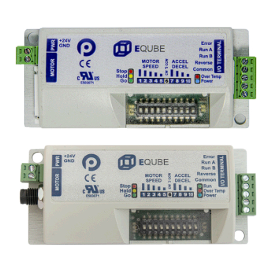
Page 11: Identifying Module Components
PULSEROLLER EQUBE Reference Manual - 3.0_en 3.1. 3.1. Identif Identifying Module Components ying Module Components Module Har Module Hardwar dware e Identif Identifying Module Components ying Module Components E-Qube-N and E-Qube-P E-Qube-N and E-Qube-P Item Item Description Description Removable 24VDC Power Connector Terminal Block Senergy Motor Port –... - Page 12 PULSEROLLER EQUBE Reference Manual - 3.0_en Module Status LEDs Speed & Configuration 10 Position DIP Switch DIP Switch and LED Hinged Clear Protective Cover E-Qube-Ai-P E-Qube-Ai-P Item Item Description Description Removable 24VDC Power Connector Terminal Block Senergy-Ai Motor Port – 4-pin M8 style header for...
- Page 13 PULSEROLLER EQUBE Reference Manual - 3.0_en Speed & Configuration 10 Position DIP Switch DIP Switch and LED Hinged Clear Protective Cover Page 13 of 79...
-
Page 14: Mounting Dimensions
PULSEROLLER EQUBE Reference Manual - 3.0_en 3.2. 3.2. Mounting Dimensions Mounting Dimensions Module Har Module Hardwar dware e Mounting Dimensions Mounting Dimensions Mounting dimensions are identical between all E-Qube models. Mounting Considerations Mounting Considerations EZ-Qube module must be mounted with its long side parallel to the conveyor frame and with its heat sink plate in contact with the conveyor frame. - Page 15 PULSEROLLER EQUBE Reference Manual - 3.0_en • Metal Heat Sink surface must face the conveyor frame and Heat Sink must not be accessible by any personnel without removing the module from the frame • Module must be mounted on electrically grounded metal surface or provided with a conductor wire connecting the module’s metal heat sink plate to...
- Page 16 PULSEROLLER EQUBE Reference Manual - 3.0_en Page 16 of 79...
- Page 17 PULSEROLLER EQUBE Reference Manual - 3.0_en Page 17 of 79...
-
Page 18: Power Connector
PULSEROLLER EQUBE Reference Manual - 3.0_en 3.3. 3.3. P P ower Connector ower Connector Module Har Module Hardwar dware e P P ower Connector ower Connector P P ower Connector Plug ower Connector Plug Pulseroller Order Code: 1397-0000 (Degson Part 15EDGK-3.5-02P-14) -
Page 19: Motor Connector
-N – Article Number 1310-5000 and E- E-QUBE QUBE-P – Article Number 1310-6000 -P – Article Number 1310-6000 The EQUBE Module motor port is a 9 pin JST Style connector that accommodates Pulseroller Senergy motor rollers and PGD units. P P in in Description Description Vcc –... - Page 20 F F or E- or E-QUBE QUBE- - Ai-P – Article Number 1321-6000 Ai-P – Article Number 1321-6000 The EQUBE Module-Ai motor port is a 4 pin M8 Style connector that accommodates Pulseroller Sener Senergy gy-Ai -Ai motor rollers and PGD units.
-
Page 21: I/O Connector
PULSEROLLER EQUBE Reference Manual - 3.0_en 3.5. 3.5. I/O Connector I/O Connector Module Har Module Hardwar dware e I/O Connector I/O Connector The I/O Connector is the same part number for all E-Qube models I/O Connector Plug I/O Connector Plug... - Page 22 PULSEROLLER EQUBE Reference Manual - 3.0_en Accepts +24V or 0V input for run at speed control (see section Run B Input Run A and Run B Inputs) Accepts +24V or 0V input to run motor in opposite direction Reverse Input...
-
Page 23: Inspection And Cleaning
PULSEROLLER EQUBE Reference Manual - 3.0_en 3.6. 3.6. Inspection and Cleaning Inspection and Cleaning Module Har Module Hardwar dware e Inspection and Cleaning Inspection and Cleaning When inspecting the device, the operator or maintenance personnel should visually inspect all mechanical parts and connections. The inspection should be performed on a monthly basis unless the device is not functioning as expected. -
Page 24: Technical Specifications
PULSEROLLER EQUBE Reference Manual - 3.0_en 3.7. 3.7. T T echnical Specifications echnical Specifications Module Har Module Hardwar dware e T T echnical Specifications echnical Specifications Input Power Supply 24.0VDC +15% / – 25% Requirements Input Protection Rating Class III Standby Current <... -
Page 25: Ordering Information
PULSEROLLER EQUBE Reference Manual - 3.0_en 3.8. 3.8. Or Ordering Infor dering Information mation Module Har Module Hardwar dware e Ordering Infor dering Information mation Order Code der Code Order T der Type Description Description E-Qube 24V Simple Drive Module, 1 JST Motor Port, NPN Sinking... -
Page 26: Module W Module Wiring Iring
PULSEROLLER EQUBE Reference Manual - 3.0_en 4. 4. Module W Module Wiring iring Module W Module Wiring iring P P ower Supply ower Supply Motor Gr Motor Grounding P ounding Practice ractice EQUBE EQUBE Module Module PNP PNP V V ersions... -
Page 27: Power Supply
P P ower Supply R ower Supply Requir equirements ements The power supply for any and all EQUBE Module modules should meet the following requirements: • Capable of detecting and properly handling short circuit and overload of its DC power output •... - Page 28 P P ower Supply Sizing ower Supply Sizing The current loading on the power supply for a group of EQUBE Modules depends upon the Motor Type selected. Each of the motor types available has an associated rated current that the motor will draw at rated torque and maximum speed. Each motor type also has an associated allowed current draw that is available for a period of time upon the initial starting of the motor.
- Page 29 PULSEROLLER EQUBE Reference Manual - 3.0_en starting times are shown in the following chart: Item Item V V alue alue Power supply load at rated 2.5 A torque at maximum speed Power supply load during motor 3.0 A starting period Duration of motor starting period 1.5 sec...
-
Page 30: Proper Motor Grounding Practice
Improper grounding of MDR and/or Power Supply Common may result in premature MDR and/or EQUBE Module module failure. Proper grounding techniques MUST be observed for all applications Page 30 of 79... -
Page 31: Pnp Version
Module W Module Wiring iring PNP V V ersion ersion The PNP versions of the EQUBE Module module are: E- E-QUBE QUBE-P – Article Number 1310-6000 -P – Article Number 1310-6000 E- E-QUBE QUBE- - Ai-P – Article Number 1321-6000 Ai-P –... -
Page 32: Run/Reverse Inputs
PULSEROLLER EQUBE Reference Manual - 3.0_en 4.3.1. 4.3.1. R R un/R un/Reverse Inputs everse Inputs Module W Module Wiring iring PNP V V ersion ersion R R un/R un/Reverse Inputs everse Inputs Single Single PNP PNP Module W Module Wiring iring To use the REVERSE input, either RUN A or RUN B must also be energized. - Page 33 PULSEROLLER EQUBE Reference Manual - 3.0_en W W iring Multiple iring Multiple PNP PNP Modules in P Modules in Parallel arallel Page 33 of 79...
-
Page 34: Error Output
PULSEROLLER EQUBE Reference Manual - 3.0_en 4.3.2. 4.3.2. Er Err r or Output or Output Module W Module Wiring iring PNP V V ersion ersion Er Err r or Output or Output Single Single PNP PNP Module W Module Wiring... - Page 35 PULSEROLLER EQUBE Reference Manual - 3.0_en W W iring Multiple iring Multiple PNP PNP Modules in P Modules in Parallel arallel Page 35 of 79...
-
Page 36: Npn Version
Module W Module Wiring iring NPN V V ersion ersion The NPN version of the EQUBE Module module is: E- E-QUBE QUBE-N – Article Number 1310-5000 -N – Article Number 1310-5000 E-Qube-Ai-N – Article Number 1321-5000 E-Qube-Ai-N – Article Number 1321-5000... -
Page 37: Run/Reverse Inputs
PULSEROLLER EQUBE Reference Manual - 3.0_en 4.4.1. 4.4.1. R R un/R un/Reverse Inputs everse Inputs Module W Module Wiring iring NPN V V ersion ersion R R un/R un/Reverse Inputs everse Inputs Single Single NPN NPN Module W Module Wiring iring To use the REVERSE input, either RUN A or RUN B must also be energized. - Page 38 PULSEROLLER EQUBE Reference Manual - 3.0_en W W iring Multiple iring Multiple NPN NPN Modules in P Modules in Parallel arallel Page 38 of 79...
-
Page 39: Error Output
PULSEROLLER EQUBE Reference Manual - 3.0_en 4.4.2. 4.4.2. Er Err r or Output or Output Module W Module Wiring iring NPN V V ersion ersion Er Err r or Output or Output Single Single NPN NPN Module W Module Wiring... - Page 40 PULSEROLLER EQUBE Reference Manual - 3.0_en W W iring Multiple iring Multiple NPN NPN Modules in P Modules in Parallel arallel Page 40 of 79...
-
Page 41: Dip Switch Settings Dip Switch Settings
EQUBE Reference Manual - 3.0_en 5. 5. DIP Switch Settings DIP Switch Settings DIP Switch Settings Switch Settings Each EQUBE Module module has a 10 position DIP Switch that provides settings for Speed Speed , Dir Direction ection , and A A ccel/Decel ccel/Decel . -
Page 42: Speed Dip Switches 1 Thru 5
PULSEROLLER EQUBE Reference Manual - 3.0_en 5.1. 5.1. Speed DIP Switches 1 thru 5 Speed DIP Switches 1 thru 5 DIP Switch Settings Switch Settings Speed Speed DIP DIP Switches 1 thru 5 Switches 1 thru 5 The motor speed is set by the ON or OFF state of DIP switches 1 through 5. - Page 43 PULSEROLLER EQUBE Reference Manual - 3.0_en 2200 38.0% 2400 41.5% 2600 45.0% 2800 48.5% 3000 51.5% 3200 55.0% 3400 58.5% 3600 62.0% 3800 65.5% 4000 69.0% 4200 72.5% 4400 76.0% 4600 79.5% 4800 83.0% 4900 84.5% 5000 86.0% 5100 88.0% 5200 89.5%...
-
Page 44: Speed Calculation
Table able The Speed Code Speed Code for any Pulseroller is a 2 digit number found on the label at the cable end of the unit. Once you know your Speed Code Speed Code , you can then reference these charts to get the... - Page 45 PULSEROLLER EQUBE Reference Manual - 3.0_en Gear Gear Speed Speed R R eduction eduction Code Code R R atio atio 605/9 605/9 55/3 55/3 75/11 75/11 11/3 11/3 The formula for calculating the speed in m/s is: For example, for a 75 speed code roller with a 50 mm tube diameter running at...
-
Page 46: Direction Dip Switch 6
PULSEROLLER EQUBE Reference Manual - 3.0_en 5.2. 5.2. Dir Direction DIP Switch 6 ection DIP Switch 6 DIP Switch Settings Switch Settings Direction ection DIP DIP Switch 6 Switch 6 Page 46 of 79... - Page 47 PULSEROLLER EQUBE Reference Manual - 3.0_en Motor R Motor Rotation Definition otation Definition The EQUBE Module uses a Clock-W Clock-Wise (CW) ise (CW) and Counter Clock-W Counter Clock-Wise ( ise (CCW CCW) ) motor rotation definition. The reference for this distinction is based upon viewing the MDR...
-
Page 48: Acceleration/Deceleration Dip Switches 7 Thru 10
These switches are used to select the acceleration and deceleration G for G force ce the control uses when starting and stopping the motor respectively. The EQUBE Module acceleration/deceleration control is designed to provide a constant G for constant G force or ramp... - Page 49 PULSEROLLER EQUBE Reference Manual - 3.0_en A A ccel/Decel T ccel/Decel Times when imes when SPEED SPEED setting is 100% maximum setting is 100% maximum A A ccel/ ccel/ No. . SW 7 SW 7 SW 8 SW 8 SW 9...
- Page 50 PULSEROLLER EQUBE Reference Manual - 3.0_en maximum. Because the Accel/Decel ramps are the same, if our speed is at 50% of maximum, then our acceleration and deceleration times would be 1/2 of maximum, thus 1.000 seconds for each. In our example, we start both motors at the same time and let them run for 6 seconds and then stop both at the same time.
-
Page 51: Accel/Decel Time Formula
PULSEROLLER EQUBE Reference Manual - 3.0_en 5.3.1. 5.3.1. A A ccel/Decel T ccel/Decel Time F ime For ormula mula DIP Switch Settings Switch Settings A A cceleration/Deceleration cceleration/Deceleration DIP Switches 7 thru 10 Switches 7 thru 10 A A ccel/Decel T... - Page 52 PULSEROLLER EQUBE Reference Manual - 3.0_en Page 52 of 79...
-
Page 53: Operation Operation
A and R R un B un B terminals allows you to dynamically set the speed with your digital run signals to the EQUBE Module. The following chart lists the signal states and their respective speed control: R R un A... -
Page 54: Output Signals & Led Indicators Output Signals & Led Indicators
PULSEROLLER EQUBE Reference Manual - 3.0_en 7. 7. Output Signals & LED Indicators Output Signals & LED Indicators Output Signals & Output Signals & LED LED Indicators Indicators ERROR ERROR Signal Signal The ERROR ERROR signal is a digital output that is used in conjunction with the LED... -
Page 55: Error Output And Led Status
PULSEROLLER EQUBE Reference Manual - 3.0_en 7.1. 7.1. Er Err r or Output and LED Status or Output and LED Status Output Signals & Output Signals & LED LED Indicators Indicators Er Err r or Output and or Output and LED... - Page 56 PULSEROLLER EQUBE Reference Manual - 3.0_en See Timing Diagrams in the following sections Other flash rates LED Status T Status Timing Diagrams for V iming Diagrams for Various arious Conditions Conditions Power Supply ON with Motor Connected Motor Not Connected Power Supply Voltage >32V...
-
Page 57: Power Supply On With Motor Connected
PULSEROLLER EQUBE Reference Manual - 3.0_en 7.1.1. 7.1.1. P P ower Supply ON with Motor ower Supply ON with Motor Connected Connected Output Signals & Output Signals & LED LED Indicators Indicators Er Err r or Output and or Output and LED... - Page 58 PULSEROLLER EQUBE Reference Manual - 3.0_en Page 58 of 79...
-
Page 59: Motor Not Connected
PULSEROLLER EQUBE Reference Manual - 3.0_en 7.1.2. 7.1.2. Motor Not Connected Motor Not Connected Output Signals & Output Signals & LED LED Indicators Indicators Er Err r or Output and or Output and LED Status Status Motor Not Connected Motor Not Connected... -
Page 60: Power Supply Voltage > 32V
PULSEROLLER EQUBE Reference Manual - 3.0_en 7.1.3. 7.1.3. P P ower Supply V ower Supply Voltage > 32V oltage > 32V Output Signals & Output Signals & LED LED Indicators Indicators Er Err r or Output and or Output and LED... - Page 61 PULSEROLLER EQUBE Reference Manual - 3.0_en Page 61 of 79...
-
Page 62: Voltage Drop Below 18V And Voltage Drop Below 13V
PULSEROLLER EQUBE Reference Manual - 3.0_en 7.1.4. 7.1.4. V V oltage Dr oltage Drop Below 18V and V op Below 18V and Voltage oltage Drop Below 13V op Below 13V Output Signals & Output Signals & LED LED Indicators Indicators... - Page 63 PULSEROLLER EQUBE Reference Manual - 3.0_en Page 63 of 79...
-
Page 64: Voltage Over 32V Due To Motor Overspeed
PULSEROLLER EQUBE Reference Manual - 3.0_en 7.1.5. 7.1.5. V V oltage Over 32V Due to Motor oltage Over 32V Due to Motor Overspeed Overspeed Output Signals & Output Signals & LED LED Indicators Indicators Er Err r or Output and... - Page 65 PULSEROLLER EQUBE Reference Manual - 3.0_en Page 65 of 79...
-
Page 66: Normal Operation With Motor Running Then Reverse Signal
PULSEROLLER EQUBE Reference Manual - 3.0_en 7.1.6. 7.1.6. Nor Normal Operation with Motor mal Operation with Motor R R unning then R unning then Reverse Signal everse Signal Output Signals & Output Signals & LED LED Indicators Indicators Er Err r or Output and... - Page 67 PULSEROLLER EQUBE Reference Manual - 3.0_en Page 67 of 79...
-
Page 68: Motor Current Exceeding Peak Limit
PULSEROLLER EQUBE Reference Manual - 3.0_en 7.1.7. 7.1.7. Motor Cur Motor Curr r ent Ex ent Exceeding P ceeding Peak Limit eak Limit Output Signals & Output Signals & LED LED Indicators Indicators Er Err r or Output and or Output and LED... -
Page 69: Over Current With Pwm Limiting
PULSEROLLER EQUBE Reference Manual - 3.0_en 7.1.8. 7.1.8. Over Cur Over Curr r ent with PWM Limiting ent with PWM Limiting Output Signals & Output Signals & LED LED Indicators Indicators Er Err r or Output and or Output and LED... -
Page 70: Motor Stalled With Self Stop
PULSEROLLER EQUBE Reference Manual - 3.0_en 7.1.9. 7.1.9. Motor Stalled with Self Stop Motor Stalled with Self Stop Output Signals & Output Signals & LED LED Indicators Indicators Er Err r or Output and or Output and LED Status Status... - Page 71 PULSEROLLER EQUBE Reference Manual - 3.0_en Page 71 of 79...
-
Page 72: Motor Overload With Self Stop
PULSEROLLER EQUBE Reference Manual - 3.0_en 7.1.10. 7.1.10. Motor Overload with Self Stop Motor Overload with Self Stop Output Signals & Output Signals & LED LED Indicators Indicators Er Err r or Output and or Output and LED Status Status... - Page 73 PULSEROLLER EQUBE Reference Manual - 3.0_en Page 73 of 79...
-
Page 74: Module Over Heat With Self Stop
PULSEROLLER EQUBE Reference Manual - 3.0_en 7.1.11. 7.1.11. Module Over Heat with Self Stop Module Over Heat with Self Stop Output Signals & Output Signals & LED LED Indicators Indicators Er Err r or Output and or Output and LED... -
Page 75: Motor Not Running When Run Is On
PULSEROLLER EQUBE Reference Manual - 3.0_en 7.1.12. 7.1.12. Motor Not R Motor Not Running when RUN is ON unning when RUN is ON Output Signals & Output Signals & LED LED Indicators Indicators Er Err r or Output and or Output and LED... -
Page 76: Motor Phases Error Detected
PULSEROLLER EQUBE Reference Manual - 3.0_en 7.1.13. 7.1.13. Motor Phases Er Motor Phases Err r or Detected or Detected Output Signals & Output Signals & LED LED Indicators Indicators Er Err r or Output and or Output and LED Status... - Page 77 PULSEROLLER EQUBE Reference Manual - 3.0_en Page 77 of 79...
-
Page 78: Motor/Module Data Mismatch
PULSEROLLER EQUBE Reference Manual - 3.0_en 7.1.14. 7.1.14. Motor/Module Data Mismatch Motor/Module Data Mismatch Output Signals & Output Signals & LED LED Indicators Indicators Er Err r or Output and or Output and LED Status Status Motor/Module Data Mismatch Motor/Module Data Mismatch... -
Page 79: Motor Data Missing
PULSEROLLER EQUBE Reference Manual - 3.0_en 7.1.15. 7.1.15. Motor Data Missing Motor Data Missing Output Signals & Output Signals & LED LED Indicators Indicators Er Err r or Output and or Output and LED Status Status Motor Data Missing Motor Data Missing...
Need help?
Do you have a question about the EQUBE and is the answer not in the manual?
Questions and answers