Aastra 470 System Manual
Hide thumbs
Also See for 470:
- User manual (28 pages) ,
- Installation manual (22 pages) ,
- Getting started (10 pages)
Table of Contents
Advertisement
Quick Links
Aastra Business Communication
Solution
Aastra 470 as of R3.0
System Manual
Platforms supported:
Aastra 470
This document contains information on the expansion
stages, system capacity, installation, configuration, run-
ning and maintenance of this Aastra communication
systems as well as their technical data.
It is intended for planners, installers and system manag-
ers of Aastra 400 communication systems.
syd-0337_en / 1.5 – R3.0 – © 05.2013
Advertisement
Table of Contents

Related Manuals for Aastra 470


Summary of Contents for Aastra 470
- Page 1 Aastra 470 This document contains information on the expansion stages, system capacity, installation, configuration, run- ning and maintenance of this Aastra communication systems as well as their technical data. It is intended for planners, installers and system manag- ers of Aastra 400 communication systems.
-
Page 2: Table Of Contents
2. 4 Aastra system phones and clients ....... .20 2. 5 Diverse phones, terminals and equipment. - Page 3 Fitting IP Media modules ........111 Aastra 470 ab R3.0...
- Page 4 4. 8. 1. 2 Aastra 5360/5361/5370/5380 ........171 4.
- Page 5 6. 2. 3 Software system Aastra DECT ........219 6.
- Page 6 Operating state and error displays......269 Aastra 470 ab R3.0 syd-0337/1.5 – R3.0 – 05.2013...
- Page 7 Aastra DECT Radio units ........
-
Page 8: Product And Safety Information
The expansion possibilities for the Aastra 470 communication server include an ap- plications server for unified communications and multimedia services, an FMC Controller for integrating mobile phones, an open interface for application devel- opers and a multitude of expansion cards and modules. - Page 9 • Make sure that the versions of the user documents comply with the software level of the Aastra 400 products used and that you have the latest editions. • Always read the user documents first before you install, configure and put a Aastra 400 communication solution into operation.
- Page 10 All parts and components of the Aastra 400 communication solution are manufac- tured in accordance with ISO 9001 quality guidelines. The relevant user information has been compiled with the utmost care. The functions of the Aastra 400 products have been tested and approved after comprehensive conformity tests. Nonethe- less errors cannot be entirely excluded.
-
Page 11: Safety Information
Hazard warnings are affixed whenever there is a risk that improper handling may put people at risk or cause damage to the Aastra 400 product. Please take note of these warnings and follow them at all times. Please also take note in particular of hazard warnings contained in the user information. -
Page 12: Data Protection
Protection against listening in and recording The Aastra 400 communication solution comprises features which allow calls to be monitored and recorded without the call parties noticing. Inform your customers that these features can only be used in compliance with national data protection provisions. -
Page 13: About This System Manual
The system functions and features, the DECT planning and the possibilities for networking several systems into a private net- work (PISN) or an Aastra Intelligent Net (AIN) are not part of this Manual; they are described in separate documents. - Page 14 Failure to observe information identified in this way can cause a defect to a module. Warning Failure to observe information identified in this way can lead to damage caused by electrostatic discharge. Aastra 470 ab R3.0 syd-0337/1.5 – R3.0 – 05.2013...
-
Page 15: About Aastra
North America, Europe and Africa as well as Internet Service Providers and distributors of renown. Aastra Technologies Limited, (TSX: “AAH”), is a leading company at the forefront of the enterprise communication market. Aastra has its headquarters in Concord, On- tario, Canada. -
Page 16: System Overview
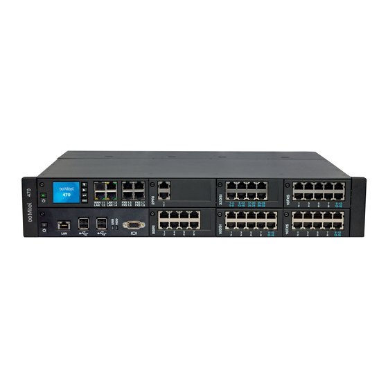
2. 2 Communication server Aastra 470 is the most powerful communication server in the Aastra 400 series. It is designed for installation in a 19” rack, but can also be set up on a flat surface. With the exception of the power supply and earthing, all the connections and con- trol elements are accessible from the front. -
Page 17: Positioning
Applications range from small businesses or branches to large companies at one or more locations. Up to 36 users can be operated on the Aastra 470 communication server without licensing. And with an expansion licence up to 400 users are possible. -
Page 18: Networking Possibilities
Aastra Intelligent Net (AIN) In an AINseveral communication servers of the Aastra 400 series can be connected up to form a homogeneous communication system. The single systems are con- nected with one another via the IP network, thereby forming the nodes of the over- all AIN system One node acts as the Master and controls the other (satellite) nodes. - Page 19 The most common protocol used is QSIG/PSS1, which sup- ports several more features than the DSS1 protocol. Virtual and leased-line networking can also be used in combination. Aastra systems are well as third-party systems can be used.
-
Page 20: Aastra System Phones And Clients
System Overview 2. 4 Aastra system phones and clients Aastra system phones stand out by virtue of their high level of user convenience and their attractive design. The broad range of products ensures there is a suitable model for every use. - Page 21 • Can be used as operator console • Wall mounting possible when combined with expansion • Web configuration interface key module Note: The Aastra 5360ip IP system phone is supported as before. Aastra 470 ab R3.0 syd-0337/1.5 – R3.0 – 05.2013...
- Page 22 • All the system features can be used • OIP client application for a professional PC operator console • Can be used purely as an IP softphone (Aastra 1560ip) or together with a system phone (Aastra 1560) • Graphical user interface with mouse and keyboard operation •...
- Page 23 • All the system features can be used • FMC client for mobile phones (runs on various operating systems) • Integrates the mobile phone into the Aastra communication system • User is always reachable under the same call number (One Number con- cept) •...
- Page 24 (can only be used with Aastra SIP-DECT®). Note: The Aastra 610d, Aastra 620d, Aastra 630d, Office 135/135pro and Office 160pro/Safeguard/ATEX) cordless sys- tem phones are supported as before (not all system features can be used). Tab. 6 SIP Multimedia Terminal Aastra BluStar 8000i...
- Page 25 System Overview Tab. 7 SIP phones of the Aastra 6730i series Additional model-specific fea- Product Principal common features tures • User-friendly registration, configu- Aastra 6731i: ration and operation of system fea- • Integrated 10/100 Mbit Ethernet tures through Aastra 400 integra- switch for connecting a PC tion.
- Page 26 Message dis- time and language. play on/off, delete redial key mem- ory. • Ideally suited for hospitality and hotel environments Note: The Aastra 1910 and Aastra 1930 analogue phones are still supported. Aastra 470 ab R3.0 syd-0337/1.5 – R3.0 – 05.2013...
-
Page 27: Diverse Phones, Terminals And Equipment
2. 5 Diverse phones, terminals and equipment Thanks to the use of international standards other clients, terminals and phones, Aastra and third-party, can be connected and operated on the communication server: • SIP-based phones With the integrated SIP protocol SIP-based phones (softphones, hardphones) - or via an SIP access point also WLAN and DECT phones - can be connected to the communication server. -
Page 28: Solutions
• Mobility Mobility solutions – above all the Aastra Mobile Client (AMC) – offer employees the possibility of integrating their mobile phone into the company network. The AMCC30 and AMCC125 controllers allow mobile users to move back and forth between the internal WLAN coverage and the mobile radio network without the call being interrupted. -
Page 29: Applications And Application Interfaces
The Aastra applications Open Interfaces Platform (OIP),Telephony Web Portal (TWP), Aastra 400 CCS run either on the integrated applications server or on a cus- tomer server. The fax service is offered exclusively on the integrated application server. - Page 30 System Overview Application Main features • Aastra 400 CCS is an additional application for the Aastra 400 Call Center, and provides statistics / reporting functions and agent monitoring (CCS = call centre supervision). The licensing of the application is made via Aastra 400 CCS OIP.
- Page 31 • Software package for the configuration and monitoring of a single system or an entire network (AIN) • Contains auxiliary applications such as Smart Software Update, System Aastra Management Search and Aastra WAV Converter Suite (AMS) • Access control with user accounts and configurable authorization profiles • Online and offline configuration possible •...
-
Page 32: Application Interfaces
Open Interfaces Platform (OIP). This open interface allows the applications to be deeply integrated with telephony. Third-party applications can also be inte- grated on systems of the Aastra 400 series via different interfaces without OIP. 2. 7. 2. 1... - Page 33 OIP on several communication servers An OIP server can also be used as in an Aastra Intelligent Net. To do so, it will be linked to the Master. It is then possible for instance to obtain network-wide call log-...
-
Page 34: Message And Alarm Systems
In addition the duration of the tone as well as its volume and melody can be freely defined by the user for each alarm. The cordless DECT phone Aastra 630d is specially designed for applications in the security and alarming sector. Besides a special alarm button it also features a man- down alarm, a no-movement alarm and an escape alarm. -
Page 35: Cti - Computer Telephony Integration
CTI workstations and is easily implemented. Connection via Ethernet Aastra 400 supports First-Party CTI on all system phones via the Ethernet interface. For this purpose the First-Party TAPI Service Provider (AIF-TSP) is required. Application example •... -
Page 36: Isdn Interface
2. 7. 2. 4 ISDN interface Aastra 400 supports the ISDN protocols ETSI, DSS1 and QSIG. Besides the possibility of networking various systems into a PISN (Private Integrated Services Network) via the ISDN interface, these protocols also provide various functions that can be used for connecting external applications (e.g. -
Page 37: System Monitoring
The configuration is carried out using either the AMS Configuration Manager or WebAdmin. The Aastra 5380/5380ip reception phone or the web-based Aastra Hospitality Manager application is available to op- erate the functions. A connection to a Property Management System (PMS) via the communication server's Ethernet interface is also possible. -
Page 38: Connection Options
Fixed Mobile Convergence Controller Monitor Aastra Mobile Client Plus Ethernet Applications server Keyboard, mouse, etc. Ethernet Message and alarm systems Hotel Management Systems Fig. 4 Overview of interfaces with possible terminal equipment Aastra 470 ab R3.0 syd-0337/1.5 – R3.0 – 05.2013... -
Page 39: Expansion Stages And System Capacity
With the project data the optimum hardware configuration is easily determined using the project plan- ning application Aastra Plan. Aastra 470 ab R3.0 syd-0337/1.5 – R3.0 – 05.2013... -
Page 40: Overview
Fig. 5 Overview of the expansion possibilities The basic system Aastra 470 can be expanded not just with interface cards and sys- tem modules but also with an applications card (CPU2). The applications card is supplied with preinstalled operating system, unified communications and multi- media applications. -
Page 41: Basic System
3. 2 Basic system The Aastra 470 basic system consists of the following components: • Metal housing (2 height units) suitable for installation in a 19" rack or for desktop installation. • CPU1 call manager card, fitted with a Flash card, a RAM module and an EIM card. - Page 42 Redundant fan unit as an option (RFU) Backplane (BP2U) Call Manager card (CPU1) Plug-in connections for the interface cards Fig. 7 Aastra 470 basic system fitted with a redundant fan unit Aastra 470 ab R3.0 syd-0337/1.5 – R3.0 – 05.2013...
-
Page 43: Interfaces, Display And Control Elements
Connectors inside the housing Earth connection Mains socket for 115/230V power supply input Voltage converter 115/230 V Socket for auxiliary power supply unit APS2 1 fewer slot if CPU2 application card is fitted Aastra 470 ab R3.0 syd-0337/1.5 – R3.0 – 05.2013... - Page 44 The figure below shows the positions of the interfaces and of the display and con- trol elements on the call manager card. [10] Fig. 9 Interfaces, display and control elements of the call manager card CPU1 Aastra 470 ab R3.0 syd-0337/1.5 – R3.0 – 05.2013...
- Page 45 Slot for IP Media module Can be fitted as an option Slot for RAM module Device ships already equipped Slot for EIM card [10] Device ships already equipped Multifunctional analogue interfaces Aastra 470 ab R3.0 syd-0337/1.5 – R3.0 – 05.2013...
-
Page 46: Power Supply
Power supply Internal power supply unit PSU2U The Aastra 470 communication server is powered as standard directly with a mains cable. The voltage converter needs to be set to the correct position to match the mains power (230 VAC or 115 VAC) (see also "Powering the communication server",... - Page 47 Mains power 115/230 VAC Fig. 10 Overview of the Aastra 470 power supply concept Notes – It is also possible to operate the communication server with the exter- nal power supply unit APS2 only In this case redundancy operation is of course no longer possible.
-
Page 48: Ethernet Concept
3. 2. 3 Ethernet concept Aastra 470 provides three GBit Ethernet interfaces, which are routed to the front panel of the call manager card. They are used to connect to the customer’s data network (LAN) and e.g. the IP connection with an SIP provider. The socket marked "WAN"... -
Page 49: Dsp Resources
(see "DSP module", page 51) and IP media modules (see "IP media mod- ules", page 58). The functions of the DSP chips on the DSP modules can also be con- figured. Aastra 470 ab R3.0 syd-0337/1.5 – R3.0 – 05.2013... - Page 50 For this the DSP chip on the Call Manager card has to be loaded with different firmware. Additional functions require the use of one or more DSP modules. Some of these functions are subject to a licence. Aastra 470 ab R3.0 syd-0337/1.5 – R3.0 – 05.2013...
-
Page 51: Expansion With Cards And Modules
Expansion Stages and System Capacity 3. 3 Expansion with cards and modules An Aastra 470 basic system can be individually expanded using interface cards, sys- tem modules and an application card. The number and position of the available slots are described in the chapter "Interfaces, display and control elements",... - Page 52 The necessary DSP resources are located on the IP media modules themselves. Standard media switch and IP media switch are independent of each other and can be used as a mix (see "IP media modules", page 58). Aastra 470 ab R3.0 syd-0337/1.5 – R3.0 – 05.2013...
- Page 53 "Configuration of DSP chips", page 56). Note With the Aastra 470 communications server G.711 voice channels are always used for voice mail, Auto Attendant and call recording. The SVM mode parameter can therefore not be changed for this system. •...
- Page 54 • Music on hold In normal operation, all IP endpoints are registered on • Conversation recording the master – even when these are located locally on the • Queue with announcement satellite. Aastra 470 ab R3.0 syd-0337/1.5 – R3.0 – 05.2013...
- Page 55 VoIP Channels for Standard Media secure data transmission using the SRTP Switch licence is required for each VoIP protocol. channel. The Secure VoIP licence valid right across the system is also required. Aastra 470 ab R3.0 syd-0337/1.5 – R3.0 – 05.2013...
- Page 56 All the possible combinations are listed, with the maximum number of voice channels. Tab. 19 Max. number of voice channels per DSP chip on CPU1, SM-DSPX1 or SM-DSPX2 DECT VoIP FoIP Audio Remarks Aastra 470 ab R3.0 syd-0337/1.5 – R3.0 – 05.2013...
- Page 57 – The system has to be restarted for the configuration changes of the DSP to take effect. – After a first start all the DSP chips are configured on DECT. Although no longer available, the module is still supported. Aastra 470 ab R3.0 syd-0337/1.5 – R3.0 – 05.2013...
-
Page 58: Ip Media Modules
The number of VoIP channels per IP media module depends on both the type of module and the use of voice channels: Tab. 22 Max. number of voice channels per IP media module G.711 only, G.711/G.729, Type FoIP (T.38) Secure G.711 Secure G.711/G.729 EIP1-8 EIP1-32 Aastra 470 ab R3.0 syd-0337/1.5 – R3.0 – 05.2013... -
Page 59: Call Charge Modules
Type 4FXO trunk card 8FXO trunk card 16FXO trunk card 4TAX – – 8TAX – – 16TAX – – The availability of the call charge modules depends on the sales channel. Aastra 470 ab R3.0 syd-0337/1.5 – R3.0 – 05.2013... -
Page 60: Interface Cards
The splits can also be made elsewhere, e.g. using system cables available separately (see "Prefabricated system cable 4 x RJ45", page 115). Fig. 15 Example of an interface card (2PRI with 2 IP media modules fitted) Aastra 470 ab R3.0 syd-0337/1.5 – R3.0 – 05.2013... -
Page 61: Trunk Cards
• 1 call charge module can be fitted for 16 ports 1 fewer card if CPU2 application card is fitted The availability of the FXO trunk cards depends on the sales channel. Aastra 470 ab R3.0 syd-0337/1.5 – R3.0 – 05.2013... -
Page 62: Terminal Cards
• All interfaces configurable to BRI-T 4 BRI-S 8BRI • Four fixed BRI-T interfaces • 4 BRI-S interfaces configurable to BRI-T 1 fewer card if CPU2 application card is fitted Aastra 470 ab R3.0 syd-0337/1.5 – R3.0 – 05.2013... -
Page 63: Applications Card Cpu2
The Windows operating system and the Aastra applications Open Interfaces Plat- form (OIP) and the fax service are preinstalled on the application card’s standard PC. On the CPU2 applications card, the Aastra Telephony Web Portal (TWP) applica- tions are additionally pre-installed. - Page 64 Installing user-specific applications is prohibited. See also: Informations about the installation, configuration and software update of the applications card can be found in the Installation Instructions for the CPU2 application card. Aastra 470 ab R3.0 syd-0337/1.5 – R3.0 – 05.2013...
-
Page 65: System Capacity
Note: The values in the following three tables relate to a communication server with an Aastra 470 Expansion expansion licence. Without this licence the system is limited to the first 36 users in the numbering plan, which means many values in the table are not valid. - Page 66 Profiles per mailbox for Auto Attendant Call data memory internal (number of records) 1000 1000 Private contacts 12000 12000 Call list entries 16000 16000 Busy lamp field buttons on Aastra SIP phones in total 1000 1000 Aastra 470 ab R3.0 syd-0337/1.5 – R3.0 – 05.2013...
- Page 67 Without expansion licence limited to 36 users For Russia maximum 256 users Only one operator console, one Aastra 2380ip, one Aastra 8000i, one Aastra BluStar for PC and two DECT cordless phones are possible per user. In the Secure VoIP modes the maximum values cannot be achieved with the selection i the DSP settings: G.711: 3 ...
-
Page 68: Terminals
DHCP clients on internal DHCP server IP terminals Aastra 2380ip Aastra 5360ip Aastra 5361ip Aastra 5370ip Aastra 5380ip IP operator consoles / IP operator Aastra 5380ip applications Aastra 1560ip Office 1560IP Aastra 470 ab R3.0 syd-0337/1.5 – R3.0 – 05.2013... - Page 69 Operation on 2 DSI interfaces in each case Maximum of 2 simultaneous call connections. Transmission with the T.38 protocol is recommended for Fax over IP. The corresponding DSP resources need to be allocated. Aastra 470 ab R3.0 syd-0337/1.5 – R3.0 – 05.2013...
-
Page 70: Terminal And Network Interfaces
Use of the call manager software requires a licence. Additional licences are required in order to use a number of enhanced functions and protocols, to enable voice channels or to operate certain terminals. The Aastra Plan application automatically plans the necessary licences, which are then enabled on the communication server using a licence code. - Page 71 Tab. Aastra Intelligent Net In an AIN with an Aastra 470 as Master and more than 36 users, an Aastra 470 Expansion licence is required only for the Master. The Aastra 470 satellites do not need a licence, even if they have more than 36 users (except of course for offline operations lasting more than 2 hours).
- Page 72 Advanced Messaging licence. • Basic Aastra Intelligent Net This licence allows an Aastra Intelligent Net to be set up and operated with one Master and one satellite. • Aastra Intelligent Net Satellites An upgrade licence for each additional satellite is required to integrate more than one satellite in an Aastra Intelligent Net.
- Page 73 8000i Desktop Media Phone, for cordless terminals logged on via Aastra SIP DECT or Aastra SIP WLAN base stations, and for SIP users for the TWP application (Telephony Web Portal), one licence is required per terminal or user. The licences are needed when registering the terminals or the user on the system.
- Page 74 This licence enables the conversion of voice channels for VoIP-non VoIP connec- tions and is used for IP terminals, SIP terminals, SIP access channels or to operate an Aastra Intelligent Net. High voice data compression is possible with the standard VoIP channels (G.729). One voice channel is activated with each li- cence.
- Page 75 • Aastra 2380ip Softphones One licence per terminal is required to operate the IP softphones Aastra 2380ip. The licences are needed to register the terminals on the system. • Aastra Dialog 4200 Phones One licence per phone is required to operate Dialog 4220, Dialog 4222 and Dialog 4223 digital phones.
- Page 76 In an AIN the Enterprise Voice Mail and Audio Record & Play Channels licences are all acquired for the Master. The number of Audio Record & Play Channels licences determines the maximum number of simulta- Aastra 470 ab R3.0 syd-0337/1.5 – R3.0 – 05.2013...
- Page 77 • Hospitality Manager This licence allows you to use the Aastra Hospitality Manager. The Aastra Hospi- tality Manager is a web-based application for receptionists in the hospitality sec- tor. One licence is required per system /AIN. •...
- Page 78 • G.729 Codec This licence allows the use of a G.729 codec for the voice channel of Aastra SIP phones, IP system phones and SIP network interfaces (also for SIP networking). The licences are always used wherever they are required. Aastra SIP-DECT® and standard SIP terminals do not require this licence.
- Page 79 It consists for selected sectors of basic, comfort and premium solutions and is installed on an external server. The licences are stored in Aastra 400. OpenCount obtains the licences via the XML based inter- face Open Application Interface.
- Page 80 Expansion Stages and System Capacity – Aastra OpenCount Functional Upgrade to Premium This additional licence offers extra functions such as intermediate statements, invoicing etc. – Aastra OpenCount Users This additional licence enables a defined number of users to be monitored via OpenCount.
- Page 81 ✓ Aastra 470 Expan- Number of users on Limited only by In the AIN, – sion the communication the system capac- only on the server Master; other- wise per node. Aastra 470 ab R3.0 syd-0337/1.5 – R3.0 – 05.2013...
- Page 82 ✓ ✓ SIP Terminals Number of regis- 1 additional In the AIN, tered standard SIP standard SIP ter- only on the terminals minal per licence Master; other- wise per node. Aastra 470 ab R3.0 syd-0337/1.5 – R3.0 – 05.2013...
- Page 83 Master; other- wise per node. ✓ ✓ Analogue Modem Use of the modem unavailable enabled In the AIN, functionality on an only on the Aastra 415/430. Master; other- wise per node. Aastra 470 ab R3.0 syd-0337/1.5 – R3.0 – 05.2013...
- Page 84 B- channel only on the ously on the PRI Master; other- interface card of an wise per node. Aastra 415, Aastra 430 or Aastra 470. TWP Connection Connection to unavailable enabled Licence is ena- – – Telephony Web Por-...
- Page 85 BluStar client to a for BluStar client. only on the Aastra 400 MS Lync server 1, 20 or 50 simul- Master; other- taneous connec- wise per node. tions options per licence. Aastra 470 ab R3.0 syd-0337/1.5 – R3.0 – 05.2013...
- Page 86 In the AIN, Basic Package uisite for all other only on the OpenCount licences. Master; other- Enables connection wise per node. to the Aastra 400 and the use of basic func- tions. ✓ ✓ Aastra OpenCount Additional licence: unavailable enabled...
- Page 87 Back-licensing is not provided for. However, resetting to the factory set- ting is possible. OIP licences OIP licences are managed by OIP itself. A detailed description of the OIP licences can be found in the System Manual Open Interfaces Platform. Aastra 470 ab R3.0 syd-0337/1.5 – R3.0 – 05.2013...
-
Page 88: Power Supply Capacity
DSP modules, the IP media modules, the CPU2 applications card and the re- dundant fan unit (P ) from the power specifications in Tab. 33 total Tab. 34 Power requirements of hardware components Aastra 470 Designation Output P [W] Basic system with CPU1 call manager card Interface card 1PRI Interface card 2PRI... - Page 89 – SB-4+ radio unit: Active call connection on 2 channels – SB-8 radio unit: Active call connection on 4 channels – Background lighting Aastra 5380: 30% active – LEDs on terminals and expansion key modules: 20% active. – Wire diameter: 0.5 mm –...
- Page 90 The value applies to phones with hardware version "-2". The value for phones with hardware version "-1" is 60 mW lower. The value depends greatly on the terminal type. With the planning application Aastra Plan the power supply available for terminals is checked automatically. Aastra 470 ab R3.0...
- Page 91 If an overload occurs, either reduce the required supply power (e.g. by powering DECT radio units and or system phones locally) or use the external auxiliary power supply unit for terminals. Aastra 470 ab R3.0 syd-0337/1.5 – R3.0 – 05.2013...
-
Page 92: Power Supply Per Interface
• Terminals used incl. auxiliary devices • Bus configuration • Line length and conductor cross-section For information on the calculations refer to "Terminal interfaces", page 132. Aastra 470 ab R3.0 syd-0337/1.5 – R3.0 – 05.2013... -
Page 93: Installation
Installation Installation This Chapter tells you the ways in which Aastra 470 can be installed and the conditions to be observed. It also includes the mounting into a 19” rack, the correct way to connect the earthing, and the power supply. Other topics in this chapter include how to fit system modules and interface cards. -
Page 94: Fitting The Communication Server
Installation 4. 2 Fitting the communication server The Aastra 470 communication server is designed for installation in a 19” rack (2 height units). The communication server can also simply be placed on a flat sur- face. Wall-mounting is not allowed. -
Page 95: Safety Regulations
Always touch the earthed metal case of the communication server before carrying out work inside the housing. This also applies to interface cards and system modules that are no longer packed inside the ESD protective wrapping. Aastra 470 ab R3.0 syd-0337/1.5 – R3.0 – 05.2013... -
Page 96: Flow Of Hot Air
4. 2. 4 Flow of hot air The Aastra 470 communications server ships with a fan already pre-installed. The housing is designed so the air flow is first guided at two levels over the processor cards and the interface cards, then passes through cutouts in the backplane, ab- sorbs the heat from the power supply unit, and exits the housing through the fan aperture. -
Page 97: Desktop Installation
4. 2. 6 Rack-mounting The rack mounting of the Aastra 470 communication server allows it to be installed horizontally in a 19” rack. Be sure to observe the following: • The communication server takes up the space of 2 height units (units) inside the 19”... -
Page 98: Rack-Mounting Procedure
Fans have a limited service life. So if a fan fails become of age ( approx. 5 years) it is advisable to replace both fans as a precautionary measure. Materials required: • Aastra 470 additional fan premounted on fastening frame • Set of screws for additional fan • Screwdriver Aastra 470 ab R3.0... - Page 99 6. Fit the upper rear housing cover. 7. Reconnect the communication server to the power supply. Standard fan Redundant fan unit Fastening frame Fig. 19 Fitting the additional fan in Aastra 470 Aastra 470 ab R3.0 syd-0337/1.5 – R3.0 – 05.2013...
-
Page 100: Earthing And Protecting The Communication Server
Operation on an IT current distribution system: The communication server can be operated on an IT power distribution system as per EN/IEC 60950 with voltages of up to 230 VAC. Aastra 470 ab R3.0 syd-0337/1.5 – R3.0 – 05.2013... -
Page 101: Connecting The Earthing Wire
2,5 mm protected 4,0 mm protected 4,0 mm Building earth unprotected Building earth unprotected Fig. 21 Earthing of the communication server in the case of an direct cabling and indirect cabling Aastra 470 ab R3.0 syd-0337/1.5 – R3.0 – 05.2013... -
Page 102: Connecting The Cable Screening
Connect the cable screens to one another at the splitting point only. Observe the tree structure principle to prevent earth loops. Socket-outlets (Main) distribution board Communica- tion server No earth loops Fig. 22 Tree structure principle Aastra 470 ab R3.0 syd-0337/1.5 – R3.0 – 05.2013... -
Page 103: Powering The Communication Server
Suitable for a typical system configuration external auxiliary power sup- with power supply redundancy ply unit External auxiliary power sup- 240 Watt Minor heat generation inside the Aastra ply unit only 470 housing Internal power supply unit + 360 Watt Suitable for maximum power require-... -
Page 104: Internal Power Supply Unit
The voltage automatically adapts to the mains voltage. Voltage selector – 24 VDC Auxiliary power suply unit (APS2) Mains power 115/230 V Fig. 23 Power supply to the communication server Aastra 470 ab R3.0 syd-0337/1.5 – R3.0 – 05.2013... - Page 105 The following diagram shows the fan-out-panel FOP from below with the auxiliary power supply fitted. Connection panel FOP Fastening board Auxiliary power suply unit (APS2) Fastening board Fig. 24 Fan-out-panel with auxiliary power supply fitted (viewed from below) Aastra 470 ab R3.0 syd-0337/1.5 – R3.0 – 05.2013...
-
Page 106: Uninterruptible Power Supply (Ups)
The uninterrupted operation of the communication server is ensured if the UPS takes over the power supply within 20 ms of the mains outage. See also For more technical details see "Technical Data", page 280. Aastra 470 ab R3.0 syd-0337/1.5 – R3.0 – 05.2013... -
Page 107: Equipping The Basic System
Installation 4. 5 Equipping the Basic System For individual expansion the Aastra 470 basic system can be fitted with interface cards, system modules and an application card. An overview can be found in the Chapter "Expansion Stages and System Capacity", page 4. -
Page 108: Fitting Application Card Cpu2
7. Start up the applications server by pressing the On/Off button on the applica- tions card. See also: Informations about the installation, configuration and software update of the applications card can be found in the Installation Instructions for the CPU2 application card. Aastra 470 ab R3.0 syd-0337/1.5 – R3.0 – 05.2013... -
Page 109: Equipping The Call Manager Card Cpu1
(DSP module, IP Media module, call charges module). The RAM module only need to be replaced in the event of repairs or maintenance work (see "Operation and Maintenance", from page 210). Aastra 470 ab R3.0 syd-0337/1.5 – R3.0 – 05.2013... -
Page 110: Fitting Dsp Modules
8. Secure the Call Manager card back into its slot with the screw. 9. Restart the call manager by pressing the On/Off button on the call manager card. Aastra 470 ab R3.0 syd-0337/1.5 – R3.0 – 05.2013... -
Page 111: Fitting Ip Media Modules
7. Secure the Call Manager card back into its slot with the screw. 8. Restart the call manager by pressing the On/Off button on the call manager card. Proceed accordingly to fit one or two IP Media modules to a PRI trunk card. Aastra 470 ab R3.0 syd-0337/1.5 – R3.0 – 05.2013... -
Page 112: Fitting Call Charge Modules
7. Use the screw to secure the FXO card back into its slot. 8. Restart the call manager by pressing the On/Off button on the call manager card. Aastra 470 ab R3.0 syd-0337/1.5 – R3.0 – 05.2013... -
Page 113: Component Mounting Rules
– The interfaces are enabled in accordance with their designation, starting with the lower designations. This means that the terminal interfaces on the proces- sor card are always enabled before those on the interface cards. Aastra 470 ab R3.0 syd-0337/1.5 – R3.0 – 05.2013... -
Page 114: Connecting The Communication Server
On terminal cards with 16 or more interfaces some or all of the RJ45 sockets are multiply assigned. They can be split into individual RJ45 sockets using patch cables and the fan-out-panel (see "Fan-out panel FOP", page 156). Aastra 470 ab R3.0 syd-0337/1.5 – R3.0 – 05.2013... -
Page 115: Indirect Cabling
With terminal cards with 16 or more interfaces some or all of the RJ45 sockets are assigned four-fold on the front panel of the Aastra 470. With this cable they can be connected without the use of a fan-out-panel (FOP). The cable is 6 m long and at one extremity has four RJ45 connectors on which all the pins are wired. - Page 116 Aastra 470 ab R3.0 syd-0337/1.5 – R3.0 – 05.2013...
- Page 117 – white orange turquoise – violet – white – green – turquoise – violet – white – brown – turquoise – violet – white – grey – turquoise – violet – Aastra 470 ab R3.0 syd-0337/1.5 – R3.0 – 05.2013...
- Page 118 Stranded ele- Core colour Cable designation ment Connection four-wire Two-wire connection – blue – turquoise – violet – – orange – turquoise – violet – Fig. 30 Pin numbering, RJ45 connector Aastra 470 ab R3.0 syd-0337/1.5 – R3.0 – 05.2013...
-
Page 119: Connection To A Universal Building Cable Installation (Ubc)
Connecting to a UBC via a (main) distribution board (example) Communica- tion server User Patch panel Phone User side Phone Exchange side Public exchange Fig. 32 Connecting to a UBC via wiring centre (example) Aastra 470 ab R3.0 syd-0337/1.5 – R3.0 – 05.2013... -
Page 120: Cabling Interfaces
A port address is always of the type x.y. x is the number of the card slot, and y, the port number. The slot numbering starts with 1 and ends with 8 (see "Number of the Aastra 470 slots", page 107). -
Page 121: Network Interfaces
Equipping the system with interface cards provides the necessary network inter- faces. With the exception of the Ethernet interface, which also represents a network interface via SIP access, there are no network interfaces on the Aastra 470 commu- nication server. - Page 122 Tab. 44 Wiring of the BRI basic rate interface network-side Cable cores Communication server Straight patch cable BRI-T sig- BRI-T sig- Socket Socket – – – – – – – – Aastra 470 ab R3.0 syd-0337/1.5 – R3.0 – 05.2013...
- Page 123 PINX 2 signal, basic rate inter- Cable cores Network Cable cores basic rate inter- face BRI-T face BRI-T See also Chapter "Connections with basic accesses" in the PISN/QSIG Networking System Manual. Aastra 470 ab R3.0 syd-0337/1.5 – R3.0 – 05.2013...
-
Page 124: Primary Rate Interface Pri
< 125 (100 kHz), < 115 (1 MHz) Characteristic impedance Wave attenuation < 6 dB/km (100 kHz), < 26 dB/km (1 MHz) Near / crosstalk attenuation > 54 dB/100 m (1 kHz bis 1 MHz) Aastra 470 ab R3.0 syd-0337/1.5 – R3.0 – 05.2013... - Page 125 PRI signal Socket – – – – – – – – Other designations are also possible on the NT1 such as: "S2m ab" instead of "TxA/TxB" and "S2m an" instead of "RxA/RxB". Aastra 470 ab R3.0 syd-0337/1.5 – R3.0 – 05.2013...
- Page 126 Crossed patch cable signal — — — — — — — — Transmission facilities PINX 1 PINX 2 max. max. 200 m 200 m Fig. 41 Primary rate interface, networked with transmission equipment Aastra 470 ab R3.0 syd-0337/1.5 – R3.0 – 05.2013...
- Page 127 — — — — — — — Leased-line or dial-up PINX 1 PINX 2 connection Mains power Mains power Fig. 42 Primary rate access PRI, networked with leased-line or dial-up connection Aastra 470 ab R3.0 syd-0337/1.5 – R3.0 – 05.2013...
- Page 128 PRI PINX 1 PRI PINX 2 RJ45 straight patch Network Straight patch signal signal cable cable — — — — — — — — See also: System Manual “PISN / QSIG Networking” Aastra 470 ab R3.0 syd-0337/1.5 – R3.0 – 05.2013...
-
Page 129: Fxo Network Interfaces
– Inadmissible high temperatures can occur on the FXO card when con- necting to local exchanges generating a very high loop current (up to 90mA). If so, the PCB temperature monitoring deactivates the FXO Aastra 470 ab R3.0 syd-0337/1.5 – R3.0 – 05.2013... - Page 130 – Circuit type as per EN/IEC 60950: TNV-3 Connection Assignment of the RJ45 sockets on the front panel: Tab. 52 Connection FXO network interface Communication server Public analogue network FXO signal Socket – – – – – – Aastra 470 ab R3.0 syd-0337/1.5 – R3.0 – 05.2013...
- Page 131 FXO signal FXO signal Socket necting cables – – – – – – – – – – – – – – – – – – – – – – – – Aastra 470 ab R3.0 syd-0337/1.5 – R3.0 – 05.2013...
-
Page 132: Terminal Interfaces
156) or with 8-fold assigned connecting cables (see e.g. Prefabricated system cable 4 x RJ45). Multiply assigned RJ45 sockets are colour-coded in blue. Note Circuit type as per EN/IEC 60950: SELV Aastra 470 ab R3.0 syd-0337/1.5 – R3.0 – 05.2013... - Page 133 Connection of individually assigned DSI terminal interface Communication server Cable cores Connection socket Socket DSI signal DSI signal Socket – – – – – – – – – – – – Aastra 470 ab R3.0 syd-0337/1.5 – R3.0 – 05.2013...
- Page 134 Socket DSI signal DSI signal Socket – – – – – – – – – – – – – – – – – – – – – – – – Aastra 470 ab R3.0 syd-0337/1.5 – R3.0 – 05.2013...
- Page 135 (protocol) on the DSI bus can be se- lected under CM_2.1.1 in AMS: • DSI-AD2: For system phones of the Aastra 5300 series and for SB-4+ and SB-8 DECT radio units. • DSI-DASL: For system phones of the Dialog 4200 series.
- Page 136 Aastra 5370 DSI-AD2 interface 1220 Aastra 5380 DSI-AD2 interface 1340 Aastra 5370, Aastra 5380 with power supply unit DSI-AD2 interface Expansion key module Aastra M530 Aastra 5370 Expansion key module Aastra M530 Aastra 5380 Expansion key module Aastra M535 Aastra 5370, Aastra 5380...
- Page 137 DSI-AD2 bus is not the same in every case: Power available A: • Applies to all the system phones of the Aastra 5300 series and the Office series. • Applies to the SB-4+/SB-8 DECT radio units with hardware version "-1".
- Page 138 Notes – If another system phone is operated on the DSI-AD2 bus in addition to an Aastra 5361, Aastra 5370 or Aastra 5380, at least one phone must be powered by a local power supply unit. – An Aastra 5370 or Aastra 5380 with an Aastra M535 expansion key module always requires a power supply unit.
- Page 139 – Depending on the power available based on the line length on the DSI-AD2 bus the ringing and hands-free volume decreases accord- ingly. – The backlighting of the Aastra 5380 display is brighter if the phone is powered by a power supply unit. Rating examples...
- Page 140 Note: max. 25 m can be crossed unstranded. (CH: Applies also to cable type G51) Installation rules • If an Aastra DECT radio unit is used, do not connect any other system phone to the same DSI bus. • If...
-
Page 141: Bri-S Terminal Interfaces
Installation Terminals The following system terminals can be operated on the DSI-AD2 bus: • System phones of the Aastra 5300 series • Aastra DECT Radio units The system phones on an DSI-AD2 bus are addressed via a single-digit terminal se- lection digit (TSD). - Page 142 The maximum number of terminals per S bus depends on the power requirements of the terminals (see "Restrictions", page 143). 8. Connection point Communica- 2 x 100 Ω tion server max. 150 m Fig. 49 S bus, short Aastra 470 ab R3.0 syd-0337/1.5 – R3.0 – 05.2013...
- Page 143 These values are based on a wire diameter of 0.5 mm. The number of terminals is the sum of the power requirements of the individual terminals and the power available on the S bus. Aastra 470 ab R3.0 syd-0337/1.5 – R3.0 – 05.2013...
- Page 144 Fit resistors at bus extremity only Fig. 53 RJ45 connection, single socket RJ45, double Front view of RJ45 Connect housing screens Ω 2x100 Fit resistors at bus extremity only Fig. 54 RJ45 connection, double socket Aastra 470 ab R3.0 syd-0337/1.5 – R3.0 – 05.2013...
- Page 145 • ISDN Terminal Adapter • PC with ISDN card • Group 4 fax machines , etc. Two call connections are possible simultaneously for each S bus. Not possible within an AIN Aastra 470 ab R3.0 syd-0337/1.5 – R3.0 – 05.2013...
-
Page 146: Fxs Terminal Interfaces
EFOP emergency fan-out panel. In the event of a power failure the EFOP switches the connected analogue phones automati- cally and directly over to the analogue FXO exchange lines (see "Emer- gency fan-out-panel (EFOP)", page 160). Aastra 470 ab R3.0 syd-0337/1.5 – R3.0 – 05.2013... - Page 147 Connection of individually assigned FXS terminal interface Communication server Cable cores Connection socket Analogue Analogue Socket Socket signal signal – – – – – – – – – – – – Aastra 470 ab R3.0 syd-0337/1.5 – R3.0 – 05.2013...
- Page 148 Analogue Analogue Socket Socket signal signal – – – – – – – – – – – – – – – – – – – – – – – – Aastra 470 ab R3.0 syd-0337/1.5 – R3.0 – 05.2013...
- Page 149 After a first start all the FXS interfaces are configured on Phone/fax. Warning Terminals connected to FXS interfaces can be damaged if the configura- tion of the FXS interface mode is unsuitable. Note Circuit type as per EN/IEC 60950: TNV-2 Aastra 470 ab R3.0 syd-0337/1.5 – R3.0 – 05.2013...
- Page 150 10 km max. 4 km 0.6mm. Screening not required not required Transmission with the T.38 protocol is recommended for Fax over IP. The corresponding DSP resources need to be allocated. Aastra 470 ab R3.0 syd-0337/1.5 – R3.0 – 05.2013...
- Page 151 > 200 m Wire diameter, core 0.4 … 0.8 mm max. 2 200 FXS resistance Line length for a wire diameter of 0.6mm. max. 3 km Screening not required Aastra 470 ab R3.0 syd-0337/1.5 – R3.0 – 05.2013...
- Page 152 Technical data for FXS mode: External audio source Input impedance approx. 15 kW Input level configurable in AMS Input circuit asymmetrical Output resistance audio source < 1 k Installation cable NF cable screened (required for low levels) Aastra 470 ab R3.0 syd-0337/1.5 – R3.0 – 05.2013...
- Page 153 24 VDC and must not draw more than 300 mW in power. There are no special requirements for the cables. Warning Control outputs must have a floating connection. max. 25mA 24 VDC FXS interface Fig. 59 Connection for FXS mode: Control output Aastra 470 ab R3.0 syd-0337/1.5 – R3.0 – 05.2013...
- Page 154 • The same switch group can only be switched by the 2 assigned control inputs. • Control of the switch groups using the control inputs takes priority over control using function codes. Aastra 470 ab R3.0 syd-0337/1.5 – R3.0 – 05.2013...
- Page 155 AC relay must be interposed if connecting a large number of auxiliary bells. 48 VAC 48 VAC FXS interface Fig. 61 Connection for FXS mode: General Bell See also "General bell on FXS interface" in the "System Functions and Features" System Manual. Aastra 470 ab R3.0 syd-0337/1.5 – R3.0 – 05.2013...
-
Page 156: Fan-Out Panel Fop
This card has 2 four-fold assigned RJ45 sockets. The 8 individually assigned RJ45 sockets are connected directly while the 2 four-fold assigned sockets are looped via the front panel of the fan-out-panel connector (FOP) strip using 2 patch cables. Aastra 470 ab R3.0 syd-0337/1.5 – R3.0 – 05.2013... - Page 157 Overview", page 279). The internal wiring of the fan-out panel is shown in the table below. The wiring is shown for sockets 1 - 4. Sockets 5 - 8 are wired accordingly. Aastra 470 ab R3.0 syd-0337/1.5 – R3.0 – 05.2013...
- Page 158 Fan-out panel FOP Socket Signal Signal Socket – – – – – – – – – – – – – – – – – – – – – – – – Aastra 470 ab R3.0 syd-0337/1.5 – R3.0 – 05.2013...
- Page 159 (see Fig. 64). Aastra 470 Copper wire yellow/green 2,5 mm protected 4,0 mm unprotected Stranded copper yellow/green 4,0 mm unprotected Fig. 64 Connection of the FOP fan-out-panel to the protective earth Aastra 470 ab R3.0 syd-0337/1.5 – R3.0 – 05.2013...
-
Page 160: Emergency Fan-Out-Panel (Efop)
The fan-out panel EFOP takes up the space of one height unit in a rack and can be fitted directly above or below the communication server. Available as of R2.1 SP1 Aastra 470 ab R3.0 syd-0337/1.5 – R3.0 – 05.2013... - Page 161 A C / D C Auxiliary power suply 1 … 8 1 … 8 unit (APS2) Communication server relevant only with APS2 auxiliary power supply unit in redundancy operation Fig. 66 Block diagram, EFOP fan-out-panel Aastra 470 ab R3.0 syd-0337/1.5 – R3.0 – 05.2013...
- Page 162 FXS line and the exchange line prior to the emer- gency operation. – In emergency operation the emergency phone is connected directly with the analogue exchange line so no exchange access prefix has to be dialled. Aastra 470 ab R3.0 syd-0337/1.5 – R3.0 – 05.2013...
- Page 163 The patch cables are available separately in lengths of 1 and 2 m (see "Equipment Overview", page 279). The internal wiring of the 3 right-hand connection blocks is the same as for the FOP fan-out-panel (see Tab. 71). Aastra 470 ab R3.0 syd-0337/1.5 – R3.0 – 05.2013...
- Page 164 The EFOP fan-out-panel has 4 equivalent connections for the protective earthing (see Fig. 68). Warning Because analogue trunk lines are to be routed via the fan-out panel EFOP, for safety reasons the fan-out panel must be connected to the protective earth. Aastra 470 ab R3.0 syd-0337/1.5 – R3.0 – 05.2013...
- Page 165 EFOP fan-out-panel only. – In redundancy operation, connect the communication server and the APS2 auxiliary power supply unit to separately protected mains power. This will further enhance the system's operating reliability. Aastra 470 ab R3.0 syd-0337/1.5 – R3.0 – 05.2013...
-
Page 166: Ethernet Interfaces
4. 7. 6 Ethernet interfaces The communication server Aastra 470 has a Gbit Ethernet switch on the call man- ager card. Three LAN interfaces are routed to the front panel of the call manager card and labelled accordingly. The RJ45 sockets are highlighted in colour in the fig- ure below. - Page 167 The following settings are possible: Tab. 75 Configuration possibilities for Ethernet interfaces Parameter Parameter value Speed/mode <Automatic, 1G/Full-duplex, 100M/Full-duplex, 100M/Half-duplex, 10M/Full-duplex, 10M/Half-duplex> <Auto MDI/MDIX, (straight), MDIX (crossed)> Aastra 470 ab R3.0 syd-0337/1.5 – R3.0 – 05.2013...
- Page 168 0.4...0.6 mm Screening Category Cat. 5 minimum See also: Informations about the on the Ethernet interface can be found on the applications card in the Installation Instructions for the CPU2 application card. Aastra 470 ab R3.0 syd-0337/1.5 – R3.0 – 05.2013...
-
Page 169: Installing, Powering And Connecting Terminals
DSI interface on the phone RJ45 socket Signal — — — — Note: The total length of the cables from the communication server to the sys- tem phone must not be less than 10 m. Aastra 470 ab R3.0 syd-0337/1.5 – R3.0 – 05.2013... - Page 170 Carrying out a logon on the system phone: – Office 10: Press the Foxkey twice. – All other system phones: Long keypress (long click) on a function key. Set new phone type appears next. Confirm with Foxkey Yes. Aastra 470 ab R3.0 syd-0337/1.5 – R3.0 – 05.2013...
-
Page 171: Aastra 5360/5361/5370/5380
To prevent any damage to the phone, always disconnect the phone from the power supply first before connecting a headset to DHSG standard. Mounting the Bluetooth module The Aastra 5380 can also be equipped with a Bluetooth module as an option. To in- stall (see Fig. 71), proceed as follows: Aastra 470 ab R3.0... - Page 172 3. Connect the Bluetooth module. Make sure it is securely fitted (see ➂). 4. Fit the cover for the Bluetooth module back into place and press home until it snaps into place (see ➃). Aastra 470 ab R3.0 syd-0337/1.5 – R3.0 – 05.2013...
-
Page 173: Office 25, Office 35, And Office 45/45Pro
Installation Powering the phone The Aastra 5360, Aastra 5361 Aastra 5370 and Aastra 5380 system phones are nor- mally powered via the DSI bus. However there are several reasons that require pow- ering with a plug-in power supply: • Long line •... - Page 174 Connecting the expansion key module or the alphanumerical keyboard The connection of the expansion key modules and the alphanumerical keyboard to Office 35 and Office 45 is described in the relevant operating instructions. Aastra 470 ab R3.0 syd-0337/1.5 – R3.0 – 05.2013...
- Page 175 Installation Fig. 72 Wall mounting of Office 25 and Office 35 Aastra 470 ab R3.0 syd-0337/1.5 – R3.0 – 05.2013...
-
Page 176: Office 10
(Fig. 73). 2. Plug the connector into the socket-outlet. 3. If the system is configured, test the operation of the terminal. 4. Label terminal. Fig. 73 Set the DSI bus address Aastra 470 ab R3.0 syd-0337/1.5 – R3.0 – 05.2013... -
Page 177: Dect Radio Units And Cordless Phones
Office 135 can be linked using connecting strips. However, operating several phones on interconnected charging bays can lead to malfunc- tions.) • Minimum distance between charging bays with cordless phones on-hook for fault-free operation: 0.2 m. Aastra 470 ab R3.0 syd-0337/1.5 – R3.0 – 05.2013... -
Page 178: Installing The Radio Units
Office 135 charging bay. ø screw : 4 mm Mounting bracket All dimensions in mm Fig. 74 Dimensional drawing for wall-mounting the mounting bracket Aastra 470 ab R3.0 syd-0337/1.5 – R3.0 – 05.2013... - Page 179 Installation distances Connecting the radio unit 230 VAC (optional) DSI interface Socket 1 Socket 2 Sockets, external antennas ( SB-8ANT only) Fig. 76 Underside of the radio units with connection points Aastra 470 ab R3.0 syd-0337/1.5 – R3.0 – 05.2013...
- Page 180 As the DECT systems of the individual nodes in an AIN do not run syn- chronously, the two DSI interfaces of an SB-8 / SB-8ANT must always be connected to the same node. Tab. 80 Operating state display on Aastra DECT radio units LED flashing (two LEDs on the SB-8) Information green...
-
Page 181: Analogue Phones Aastra 6710A, Aastra 6730A
No symbol (any switch setting) The red MWI LED under the notification key can only be triggered with the Aastra 470 communication server and polarity reversal notification type. Set the switch on the underside of the phone to the “−” symbol. This applies to a straight phone cord (as the one included with the phone). - Page 182 Installation – The statements in this section also apply to Aastra 1910 and Aastra 1930 analogue phones. On these models, the MWI switch is on the rear of the phone and the switch settings for polarity reversal are labelled PR1 and PR2.
-
Page 183: Ip System Phones
4. 8. 6 Aastra SIP and standard SIP phones The registration of SIP system phones of the Aastra 6700i series, other Aastra SIP terminals and SIP terminals by other manufacturers as internal users is described in the "SIP and SIP terminals" System Manual. -
Page 184: Configuration
5. 1 AMS Configuration Tool The Aastra Management Suite (AMS) is a software package used for the configura- tion and monitoring of a single system or an entire network. The configuration can be prepared offline and locally or remotely loaded to the configuration server. Re- mote access means that changes and expansions can be carried out independently of time and location, and is used for the remote maintenance of the system. -
Page 185: Ams Manager
Account Manager (AM) ✓ ✓ ✓ ✓ Information Manager (IM) ✓ ✓ ✓ Upload Manager (UM) As of R3.0 is AMS is no longer supported. The Aastra Hospitality Manager is available instead. Aastra 470 ab R3.0 syd-0337/1.5 – R3.0 – 05.2013... -
Page 186: Auxiliary Applications
Windows taskbar. System Search is a help tool for detect- ing communication systems of the Aastra 400 series in the IP network. System Search finds all communication servers connected to the IP network, provided they are in the same subnetwork as the PC with AMS and have at least software release 1.0. - Page 187 The Hospitality Administrator features all the views required to set up the Aastra Hospitality Manager and the reception menu of the Aastra 5380/5380ip and spec- ify its default settings. A link can also be used to start the Aastra Hospitality Man- ager (see "Aastra Hospitality Manager", page...
-
Page 188: Access Types
External dial-up access via dial-in node (only in AIN) External dial-up access via ISDN connection via a BRI-T network interface Fig. 77 Overview of the access types See also: Detailed information can be found in the AMS Help. Aastra 470 ab R3.0 syd-0337/1.5 – R3.0 – 05.2013... -
Page 189: User Access Control
SystemUserInterface (see"Display and control panel of the call manager", page 240). The two pre-defined standard user accounts blustar bucs are intended for BluStar terminals or a BluStar server. Aastra 470 ab R3.0 syd-0337/1.5 – R3.0 – 05.2013... -
Page 190: Predefined Authorization Profiles
✓ ✓ • System Search – – – – – – – – – – ✓ ✓ • LDAP service – – – – – – – – – – Aastra 470 ab R3.0 syd-0337/1.5 – R3.0 – 05.2013... -
Page 191: Administration Rights
✓ • Set/change sales channel – – ✓ • Initialization – – ✓ • Restart – – ✓ ✓ ✓ • Status change remote maintenance ✓ • Software upload – – Aastra 470 ab R3.0 syd-0337/1.5 – R3.0 – 05.2013... -
Page 192: Interface Access
Allows IP parameters displayed in System Search to be modified directly. • LDAP service Allows LDAP clients to access the integrated LDAP server. LDAP clients can then access the system phone book. Aastra 470 ab R3.0 syd-0337/1.5 – R3.0 – 05.2013... -
Page 193: Passwords
See also: The control panel on the front panel is PIN-protected (see "PIN control panel", page 240). Aastra 470 ab R3.0 syd-0337/1.5 – R3.0 – 05.2013... -
Page 194: Syntax Of Passwords And User Names
• German umlauts (e.g. ä, ö, ü) and other diacritical characters (e.g. é, à, â) are not permitted. • User names must be unique throughout the system. • The user name and password must not be identical. Aastra 470 ab R3.0 syd-0337/1.5 – R3.0 – 05.2013... -
Page 195: Change Password
Office 45 interface access is enabled. The profile also needs to be as- signed the AMS authorization level Attendant if the remote access status is to be changed. Aastra 470 ab R3.0 syd-0337/1.5 – R3.0 – 05.2013... -
Page 196: Password-Free Access
In the case of a remote maintenance access an entry will not be generated if re- mote maintenance is barred or if CLIP required is set to in the configuration and no CLIP is received. Aastra 470 ab R3.0 syd-0337/1.5 – R3.0 – 05.2013... -
Page 197: Enabling Remote Access
Note: It is advisable not to keep the remote access authorization permanently activated. This ensures that the communication server data cannot be manipulated from a remote location by unauthorized persons. Aastra 470 ab R3.0 syd-0337/1.5 – R3.0 – 05.2013... -
Page 198: Function Code For Remote Access
This is irrespective of whether dial-up access is via a satellite or directly to the Master. Aastra 470 ab R3.0 syd-0337/1.5 – R3.0 – 05.2013... -
Page 199: Function Keys For Remote Access Authorization
Menu example of a one-off remote access on the Office 45 F12: REMOTE MAINT. ONCE ONLY BACK Tab. 89 Menu example of repeated remote access on the Office 45 F12: REMOTE MAINT. BACK Aastra 470 ab R3.0 syd-0337/1.5 – R3.0 – 05.2013... -
Page 200: Data Exchange Between Communication Server And Pc
To edit or complement system and user data, load the data either directly from the communication server file system or from the PC's hard disk (AMS database) into the main memory. Aastra 470 ab R3.0 syd-0337/1.5 – R3.0 – 05.2013... -
Page 201: Working Offline (Ams Database)
AMS database to a backup file specified by the user. If the current communication server configuration data is to be saved, it must first be loaded into the AMS database using Download (Communication server-> AMS). Aastra 470 ab R3.0 syd-0337/1.5 – R3.0 – 05.2013... - Page 202 This menu function on the AMS Shell restores configuration data from a backup file to the AMS database of all the open communication servers. Note: All the configuration data in the current AMS database will be overwrit- ten! Aastra 470 ab R3.0 syd-0337/1.5 – R3.0 – 05.2013...
-
Page 203: Working Online (Communication Server Database)
Managers (e.g. Con- figuration Manager, Fault & Maintenance Manager). New or modified hardware can be registered in AMS in this way. Aastra 470 ab R3.0 syd-0337/1.5 – R3.0 – 05.2013... - Page 204 A partial upload is only followed by a restart and disconnection of exist- ing phone connections if system data is loaded up onto the communica- tion server. In this case AMS generates an appropriate message. Aastra 470 ab R3.0 syd-0337/1.5 – R3.0 – 05.2013...
- Page 205 Music on hold from a backup or other sources • Download, compress and upload existing voice greetings. The Aastra WAV Con- verter is used for compressing and converts the wave files from audio format G.711 to audio format G.729.
-
Page 206: Import / Export Configuration Data
… Importing data from older communication servers System data from an Aastra IntelliGate system can be imported into the AMS data- base using a backup file. The AMS Shell provides an import function for this pur- pose. The following combinations of source and destination communication serv- ers are possible: Tab. -
Page 207: Configuring
The procedure for setting up and clearing down an online connection from AMS to the communication server and the steps for configuring a single system, a private network (PISN) or an Aastra Intelligent Net (AIN) are described in detail in the AMS help. - Page 208 The licences must be activated. The licence code can be edited both online and of- fline with AMS: 1. The licence has to be activated with the aid of the EID via the Aastra 400 activa- tion portal on the extranet (partner login required). The licence code issued as a...
- Page 209 5. Add system terminals, mailboxes, direct dialling numbers etc. 6. Most default values can now be read out. CPU2 applications card configuration The applications card configuration is described in the CPU2 applications card in- stallation instructions. Aastra 470 ab R3.0 syd-0337/1.5 – R3.0 – 05.2013...
-
Page 210: Operation And Maintenance
The contents of the memory are retained even when there is no power supply. • The data of applications on the applications server (if an CPU2 applications card is fitted) is stored on a hard disk. Aastra 470 ab R3.0 syd-0337/1.5 – R3.0 – 05.2013... -
Page 211: System Software
"Data exchange between communication server and PC", page 200). The file system can also be accessed with an FTP client. This is useful for instance for the software upload for Aastra SIP terminals. Aastra 470 ab R3.0 syd-0337/1.5 – R3.0 – 05.2013... -
Page 212: Boot Software
Access to the configuration data via AMS or WebAdmin is regulated by a User Ac- cess Control with user accounts, authorization profiles and authorization levels. More information can be found in the Chapter "Configuration", page 184. Aastra 470 ab R3.0 syd-0337/1.5 – R3.0 – 05.2013... -
Page 213: Update Software
Update" auxiliary application. The system software also comprises the software for the digital system phones, the IP system phones, the Aastra DECT radio units, the Aastra DECT cordless phones and the Aastra SIP phones. There are several possibilities for establishing a communication link between the communication server and the AMS Upload Manager (see "Access types",... -
Page 214: Standard Upload
Software update phase Versionen-Transfer Versionen-Transfer version transfer Fig. 80 Software upload sequence During a standard upload the communication server remains operational during the upload phase. After successful software upload, the communication server Aastra 470 ab R3.0 syd-0337/1.5 – R3.0 – 05.2013... - Page 215 7. Select a software package (zip file). If necessary, load a new software package beforehand using the button. 8. If a new licence code is required to operate the new system software, enter it un- Licence code. Aastra 470 ab R3.0 syd-0337/1.5 – R3.0 – 05.2013...
- Page 216 See also: Further information about uploading is available in Help of the Upload Manager. Aastra 470 ab R3.0 syd-0337/1.5 – R3.0 – 05.2013...
-
Page 217: Emergency Upload Of The System Software
7. Click the Upload button. The Emergency Upload is started. Note: Depending on the type of communication server, the upload process (especially unpacking the software package) can take some time. Aastra 470 ab R3.0 syd-0337/1.5 – R3.0 – 05.2013... -
Page 218: Software Of Corded System Phones
The Office 10, Office 25 and Aastra 5360 system phones do not have their own memory. The system phones Office 35, Office 45, Aastra 5370, Aastra 5380, all the IP phones of the Aastra 5300ip series and all the SIP phones of the Aastra 6753i se- ries have a Flash memory. -
Page 219: Software System Aastra Dect
There is only one software for the cordless phones of the Aastra 600c/d series. It is included in the communication server's software package and stored in the file sys- tem of the communication server. -
Page 220: Cpu2 Applications Card
Air-Download has been successfully completed. A restart is carried out on the cordless phone. 6. 2. 4 CPU2 applications card The applications card configuration is described in the CPU2 applications card in- stallation instructions. Aastra 470 ab R3.0 syd-0337/1.5 – R3.0 – 05.2013... -
Page 221: Hardware Update
In an AIN every node can be individually prebarred and unlocked again. As soon as there are no more active connections in the prebarred system, the call manager can be shut down. Aastra 470 ab R3.0 syd-0337/1.5 – R3.0 – 05.2013... -
Page 222: Licenses And Eim Card
2. The new licence code can be obtained either from your authorized dealer or via the Aastra 400 activation portal on the extranet using the EID (partner login re- quired). 3. Enter the licence code under CM_1.2_Licence code... -
Page 223: Interface Cards
4. Use the screw to secure the card in its slot. 5. Restart the call manager by pressing the On/Off button on the call manager card. Aastra 470 ab R3.0 syd-0337/1.5 – R3.0 – 05.2013... -
Page 224: New Card With Fewer Ports
However, this is pos- sible only if the configuration data of the original card was not already deleted beforehand. Aastra 470 ab R3.0 syd-0337/1.5 – R3.0 – 05.2013... -
Page 225: New Card With More Ports
4. Insert the card in the new slot in AMS and remove it from the old slot. The con- figuration data at the old slot location is now deleted. Note: Not all cards can be equipped on all slots (see "Component mounting rules", page 113). Aastra 470 ab R3.0 syd-0337/1.5 – R3.0 – 05.2013... -
Page 226: System Modules
7. Secure the Call Manager card back into its slot with the screw. 8. Restart the call manager by pressing the On/Off button on the call manager card. Aastra 470 ab R3.0 syd-0337/1.5 – R3.0 – 05.2013... -
Page 227: Change The Ip Media Module
7. Secure the Call Manager card back into its slot with the screw. 8. Restart the call manager by pressing the On/Off button on the call manager card. Proceed accordingly to replace one defective IP media module to a PRI trunk card. Aastra 470 ab R3.0 syd-0337/1.5 – R3.0 – 05.2013... -
Page 228: Replacing The Call Charge Module
7. Use the screw to secure the FXO card back into its slot. 8. Restart the call manager by pressing the On/Off button on the call manager card. Aastra 470 ab R3.0 syd-0337/1.5 – R3.0 – 05.2013... -
Page 229: Changing The Ram Module
7. Secure the Call Manager card back into its slot with the screw. 8. Restart the call manager by pressing the On/Off button on the call manager card. RAM module Metal clamps Slot approx. 30° Mainboard Fig. 81 Changing the RAM module Aastra 470 ab R3.0 syd-0337/1.5 – R3.0 – 05.2013... -
Page 230: System Cards
6. Secure the Call Manager card back into its slot with the screw. 7. Restart the call manager by pressing the On/Off button on the call manager card. Fig. 82 EIM card Aastra 470 ab R3.0 syd-0337/1.5 – R3.0 – 05.2013... -
Page 231: Replacing The Flash Card
– Flash cards that are ordered as spare parts do not contain any soft- ware. In this case an Emergency Upload has to be carried out (see "Emergency Upload of the system software", page 217). Aastra 470 ab R3.0 syd-0337/1.5 – R3.0 – 05.2013... -
Page 232: Call Manager Card Cpu1
A defective call manager card can make it impossible to read out unstored configuration data with AMS. In such cases the data can be saved using a new call manager card by replacing the Flash card. Aastra 470 ab R3.0 syd-0337/1.5 – R3.0 – 05.2013... -
Page 233: Application Card Cpu2
7. Start up the applications server by pressing the On/Off button on the applica- tions card. See also: Informations about the installation, configuration and software update of the CPU2applications card can be found in the Installation Instructions for the CPU2 application card. Aastra 470 ab R3.0 syd-0337/1.5 – R3.0 – 05.2013... -
Page 234: Replacing System Terminals
(reduced or increased) to the new phone. The features are reduced if a phone is replaced by a phone with a lower level of added features (e.g. Aastra 5380 Aastra 5370) or by a predecessor model e.g. Aastra 5380 Office 45). -
Page 235: Dect Terminals
The user of the cordless phone may have to identify himself to the system using an access code. The access code has to be entered in the system configuration prior to the logon procedure. Aastra 470 ab R3.0 syd-0337/1.5 – R3.0 – 05.2013... - Page 236 Operation and Maintenance Replacing a cordless phone (phone with microSD card) The special microSD-Card is suited for use with DECT cordless phones Aastra 620d/ 622d, Aastra 630d/632d and Aastra 650c. The card saves the subscription data of the cordless phone on your communications system, and the most important local device data.
- Page 237 Fig. 83 on the right). Note: For Aastra 620d, Aastra 630d mwith white card holders or for Aastra 622d, Aastra 632d and Aastra 650c do not use the protective cover. 7. Insert the battery and close the battery compartment. Fig. 83 microSD card Aastra 470 ab R3.0...
- Page 238 The login data and the local device data stored on the card are used. The original data remains saved in the cordless phone and is reactivated as soon as the card is removed. Aastra 470 ab R3.0 syd-0337/1.5 – R3.0 – 05.2013...
- Page 239 -> The destination cordless phone restarts 8. Switch off the destination cordless phone and remove the card. -> After the target cordless phone is switched back on, the copied user data will be used. Aastra 470 ab R3.0 syd-0337/1.5 – R3.0 – 05.2013...
-
Page 240: Display And Control Panel Of The Call Manager
On/Off key Status LED call Colour display 1.8” manager Fig. 84 Aastra 470 display and control panel 6. 4. 1 PIN control panel A number of functions executed via the navigation keys require a PIN (e.g. run first start). The PIN always consists of 4 digits and can be modified via AMS in the access con- trol using the SystemUserInterface user account: Tab. -
Page 241: Status Led
Different display patterns can be displayed in this way. Tab. 96 Examples of display patterns LED activation period Description LED lit green LED slowly flashing orange – LED flashing rapidly orange/red – – Aastra 470 ab R3.0 syd-0337/1.5 – R3.0 – 05.2013... -
Page 242: Startup And Operating State Display
To access the boot mode press the enter key during the LED test red, which is exe- cuted during the start-up phase 0. The boot mode remains active until the Emergency Upload is completed or the sys- tem is restarted manually. Aastra 470 ab R3.0 syd-0337/1.5 – R3.0 – 05.2013... -
Page 243: Error Display With Status Led
The boot mode is exited automatically and the startup then continues normally if no input is made within 3 seconds. Fig. 85 Boot menu Aastra 470 6. 4. 3. 5 Display of event messages If an event message occurs in normal operation, the LED pattern switches from "slowly flashing green"... -
Page 244: Colour Display
• Screen saver and energy saving function. Event message mode Normal operation • After one or more event messages are received. (Event message mode) Aastra 470 ab R3.0 syd-0337/1.5 – R3.0 – 05.2013... -
Page 245: Display And Control Panel Of The Application Server
– If a regular shutdown is not possible (e.g. as the application server is no longer reacting), then application card shutdown is forced after two minutes without the operating system being correctly shut down beforehand. Unsaved data are deleted. Aastra 470 ab R3.0 syd-0337/1.5 – R3.0 – 05.2013... -
Page 246: Status Leds
Note: The maximum permissible current input at the USB interfaces varies (see Tab. The Ethernet interface on the applications server is covered as there is currently no provision for its use. Aastra 470 ab R3.0 syd-0337/1.5 – R3.0 – 05.2013... -
Page 247: Operations Supervision
Maintenance external dispositivos message group • PC on Ethernet Manager endpoints that externos Interface • System Assistant can receive Office 45 e-mails Fig. 87 Distribution principle for an event message Aastra 470 ab R3.0 syd-0337/1.5 – R3.0 – 05.2013... -
Page 248: Event Types
Error, date, time failed a connection with a hotel management system (PMS system). Reason: 1: Call rejected, 2: Destination unob- tainable, 3: Destination busy, 4: Connection timeout, 5: Wrong address, 6: Unknown error Aastra 470 ab R3.0 syd-0337/1.5 – R3.0 – 05.2013... - Page 249 Dual Homing back within the There are now enough licences available for Date, time licence limit registering SIP phones in the Aastra 6700i series on a backup communication server. Note: This event message is generated by the backup communication server.
- Page 250 Cause (0: Busy /1: Not available nation not reachable /2:(not used), 2: Barred /3: not defined), date, time Internal event message desti- Local output available once again Date, time nation reachable Aastra 470 ab R3.0 syd-0337/1.5 – R3.0 – 05.2013...
- Page 251 A permanent DTMF receiver (for detection suf- BCS Ref., date, time for integrated mobile phones fix dialling function codes) could not be assigned to an integrated mobile phone with enhanced functionality. Aastra 470 ab R3.0 syd-0337/1.5 – R3.0 – 05.2013...
- Page 252 32FXS card and no more than 50 FXS ports per system. • PRI, BRI and DSI cards do not have tempera- ture sensors and are therefore never deacti- vated due to overheating. Aastra 470 ab R3.0 syd-0337/1.5 – R3.0 – 05.2013...
- Page 253 External SMS gateway unobtainable by net- Date, time work provider or incorrectly configured Software upgrade IP system The software update of an Aastra 5360ip/ User number, terminal ID, rea- phone failed 5361ip/5370ip/5380ip has failed for the stated son, date, time reason.
- Page 254 8: Hospitality/Accomodation, 9: User folder System memory usage over Memory usage in the file system for a particular User number, memory usage in the critical range user has exceeded a critical value %, date, time Aastra 470 ab R3.0 syd-0337/1.5 – R3.0 – 05.2013...
- Page 255 Date, time has been restarted ually or automatically due to an error. The licence limit for Aastra SIP An Aastra SIP terminal is unable to register or Parameter 1=1: Missing Aastra terminals has been reached use the video functionality because there are...
- Page 256 1: 3rd party), node ID or certifi- be renewed manually. cate name, date, time If the endpoint type is = 0 (Aastra), then is parameter 2 = node ID. If the endpoint type is = 1 (3rd party), then the remaining parameter data contains the first eleven characters of the certificate name.
- Page 257 Type of endpoint (0: Aastra, is about to expire and needs to be renewed. 1: 3rd party), node ID or certifi- If the endpoint type is = 0 (Aastra), then is cate name, date, time parameter 2 = node ID.
- Page 258 No recipient address Auth. CRAM-MD5 init. Invalid e-mail recipient address Auth. CRAM-MD5 Invalid e-mail sender address Reset state Action carried out by the SMTP client at the point when the error occurred. Aastra 470 ab R3.0 syd-0337/1.5 – R3.0 – 05.2013...
-
Page 259: Event Tables
No re- sponse from network, no event message needs to be sent to the signal destinations. Aastra 470 ab R3.0 syd-0337/1.5 – R3.0 – 05.2013... -
Page 260: Signal Destinations
Gateway tion server Card Local signal destina- ISDN- tions Gateway SMTP- Server Ethernet Ethernet internal or external E-mail destina- tion Fig. 88 Overview of connection possibilities for the various signal destinations Aastra 470 ab R3.0 syd-0337/1.5 – R3.0 – 05.2013... - Page 261 Depending on the event table allocated, event messages are sent to a specified ex- ternal signal destination. Two external signal destinations can be specified: • 1 preferred external signal destination • 1 alternative external signal destination Aastra 470 ab R3.0 syd-0337/1.5 – R3.0 – 05.2013...
- Page 262 < 5 / 2 Dialling attempts < 2 External event Output event message destina- message tion not available Fig. 89 Flowchart of the signalling of an event message to an external signal destination Aastra 470 ab R3.0 syd-0337/1.5 – R3.0 – 05.2013...
- Page 263 3. To use a different route, you need to configure a route selection. • Digit barring for external calls and printer faults (in the case of call logging) do not affect outgoing event messages. Aastra 470 ab R3.0 syd-0337/1.5 – R3.0 – 05.2013...
- Page 264 Shell. In the system ID you can store a serial number or the DDI number for the remote maintenance of the system (20 digits). • In the Configuration Manager: Route 3 must be allocated trunk groups with digital network interfaces (Routes setting). Aastra 470 ab R3.0 syd-0337/1.5 – R3.0 – 05.2013...
- Page 265 • User name and password of the dial-up networking of the PC or ISDN gateway, to gain access via the TA or the ISDN gateway to the PC. Configuring a local signal destination on ISDN The event messages are displayed in PC format. Aastra 470 ab R3.0 syd-0337/1.5 – R3.0 – 05.2013...
- Page 266 Forwarding to the SNMP destinations can be activated and deactivated independently of the forwarding to the local and external signal destinations. Aastra 470 ab R3.0 syd-0337/1.5 – R3.0 – 05.2013...
- Page 267 On. SNMP stands for "Simple Network Management Protocol" and is used by Network Management Systems (NMS). The systems of the Aastra 400 series support the SNMP V1 version. If the Network Management System is to know the potential events of the commu- nication system, the corresponding system components have to be defined in the form of configurable objects (Managed Objects: MO).
- Page 268 Manager. The event message is signalled without any delay, directly at the selected signal destination. If the communication server is connected with AMS via a TA, the test event mes- sages will be signalled only once the connection is cleared down. Aastra 470 ab R3.0 syd-0337/1.5 – R3.0 – 05.2013...
-
Page 269: Operating State And Error Displays
No terminal has been created on the connected port or the when off-hook. terminal created has not been allocated to a user. • Create a terminal and allocate a user • Check installation or connecting cable Aastra 470 ab R3.0 syd-0337/1.5 – R3.0 – 05.2013... -
Page 270: Operating State Of The Aastra Dect Radio Units
Operation and Maintenance 6. 6. 2. 4 Operating state of the Aastra DECT radio units Each radio unit is equipped with 3 LEDs. The operating state the radio units is indi- cated by different colours and flashing sequences in cycles of 1 s, specifically by one of the two outer LEDs on the SB-4+ and by both outer LEDs on the SB-8 / SB- 8ANT (separately for each DSI bus). -
Page 271: Malfunction Of The Aastra Dect Radio Unit
Active in the AMS Configuration Manager. 6. 6. 2. 5 Malfunction of the Aastra DECT radio unit Tab. 108 Malfunction of the Aastra DECT radio unit Error description Error cause / error handling No radio connection in a coverage area. -
Page 272: Malfunctions Of Aastra Dect Cordless Phones
• Check battery and replace if necessary. About the charging process: • Battery symbol on the cordless phone is flashing (Office 135) or filling up (Office 160, Aastra 600c/d) when the battery is being charged. • Check tone indicates correct contact. -
Page 273: Long-Clicks On Aastra Dect Cordless Phones
6. 6. 2. 8 Long-clicks on Aastra DECT cordless phones In normal DECT cordless phone operation, long-clicking the following keys ac- cesses additional functions directly. Tab. 111 Long-clicks on Aastra DECT cordless phones Aastra Function Office 135 Office 160 600c/d In a list box: change scroll direction. -
Page 274: Overload Code Displays Office 135 / Office 160
Wrong mode during logon. Logon to the system < I5 Not allowed. Mis-used • Office 135: Long-click "Home" to indicate wrong Logon to the system > I5: "design" version. • Office 135: Short-click "Home" Aastra 470 ab R3.0 syd-0337/1.5 – R3.0 – 05.2013... -
Page 275: Other Aids
NSUB: xxxx Number of PISN users in the system NSUB: 0000 0000: No PISN user in the system LINE: xxxx Number of lines in the system LINE: 0000 0000: No lines defined Aastra 470 ab R3.0 syd-0337/1.5 – R3.0 – 05.2013... - Page 276 System Assistant on the Office 45. They are stored in event table 4 (see "Event message concept", page 247). The entries in the Maintenance menu re- main stored until they are deleted with the Delete command. Aastra 470 ab R3.0 syd-0337/1.5 – R3.0 – 05.2013...
-
Page 277: Fault & Maintenance Manager
"Event message concept", page 247. 6. 6. 3. 3 Measuring equipment for cordless systems The aids required for measuring out DECT systems are described under “Planning DECT Systems” in the User’s Guide. Aastra 470 ab R3.0 syd-0337/1.5 – R3.0 – 05.2013... -
Page 278: Annex
SEV = Set packed EGV = Terminal packed MOV = Module/card packed Project number (three-digit) 958 (System Aastra 470) Country code and sales channel Two-digit country code as per ISO 3166, (one to three-digit, with full stops) Sales channel (1...9) for various sales channels. -
Page 279: Equipment Overview
Backward com- patibility is guaranteed. 7. 2 Equipment Overview Tab. 121 Equipment Overview Designation Description PBX958.EXP.A470-1 Aastra 470 basic system with CPU1 call manager card CABLE-MAINS 3X0.75MM2 3-pin network connection cable MOV958.EXP.CPU2-1 CPU2 applications card MOV958.EXP.CPU2-2 CPU2-S applications card MOV957.EXP.SM-DSPX1-1 DSP module SM-DSPX1 MOV957.EXP.SM-DSPX2-1... -
Page 280: Technical Data
• Voice path with A/D and D/A conversion (standard PCM, A-law) • Transmission as per ES 201 168 (level country-specific) • Signalling as per TBR 21 • Pulse or DTMF dialling, Flash signal Aastra 470 ab R3.0 syd-0337/1.5 – R3.0 – 05.2013... -
Page 281: Terminal Interfaces
The following technical data applies to the terminal interfaces: Digital terminal interface DSI • Proprietary interface, two-wire • Two system phones of the Aastra 5300 series can be connected per interface (AD2 protocol) • One system phone of the Dialog 4200 series can be connected per interface (DASL protocol) •... -
Page 282: Communication Server
Control output on FXS interface no isolation Audio input on FXS interface no isolation Tab. 125 Ambient conditions Condition Aastra 470 Ambient temperature 5 to 45 Relative air humidity 30 % to 80 %, non-condensating Aastra 470 ab R3.0 syd-0337/1.5 – R3.0 – 05.2013... -
Page 283: Dimensions Of Cards And Modules
481 x 44 x 69 Tab. 129 Modules Card Dimensions length x width [mm] DSP module 90 x 56 IP Media module 85 x 85 Call charge module 83 x 60 Aastra 470 ab R3.0 syd-0337/1.5 – R3.0 – 05.2013... -
Page 284: Lan Switch
"Maximal power requirements of the system phones on the DSI bus", page 136 Power consumption, IP system see System Manual for "Aastra Intelligent Net (AIN) and IP system phones" phones Tab. 133 Dimensions and weights, digital and IP system phones... -
Page 285: Aastra Dect Radio Units
The following table contains the network features as defined in the GAP standard. For each feature a separate column indicates whether it is supported by communi- cation servers of the Aastra 400 family or Aastra DECT cordless phones. Aastra 470 ab R3.0... - Page 286 PP: Portable Part Fixed Part Mandatory (this feature must be supported by GAP compliant equipment) Optional —: The Aastra DECT cordless phones and Aastra 400 communication servers do not support the feature. Aastra 470 ab R3.0 syd-0337/1.5 – R3.0 – 05.2013...
-
Page 287: Operation Of Digital System Phones
The following Latin script assignment for the digit keys applies to the system phones / Aastra 5360/5360ip, Aastra 5361/5361ip, Aastra 5370/5370ip, Office 35, Office 45/45pro, Office 135/135pro and all models of Office 160 for all communica- tion server languages with the exception of Greek: Aastra 470 ab R3.0... - Page 288 * / ( ) < = > % £ $ ¤ ¥ ¤ @ & § Space # Notes: – The Aastra 5360 and Office 25 phones does not have a graphics-com- patible display and therefore cannot display all the characters featured (see also the corresponding user guide).
-
Page 289: Aastra 5380/5380Ip Alpha Keyboard
* / ( ) < = > % £ $ ¤ ¥ ¤ @ & § Space # Notes: – The Aastra 5360 and Office 25 phones does not have a graphics-com- patible display and therefore cannot display all the characters featured (see also the corresponding user guide). -
Page 290: Alphanumerical Keyboard (Akb)
Annex Tab. 138 Integrated alphanumerical keyboard Aastra 5380/5380ip <Key> Shift + <key> Ctrl + <key> Ctrl + Shift + <key> ä á à â ã å æ Ä á à â Ã Å Æ ç Ç é è ê ë... - Page 291 Fig. 90 AKB QWERTZ Fig. 91 AKB QWERTY If an alpha keyboard (QWERTZ or QWERTY) is connected to a communication server that is set to Greek, the following keyboard assignment applies: Aastra 470 ab R3.0 syd-0337/1.5 – R3.0 – 05.2013...
-
Page 292: Function Commands (Macros)
"." Control keys function "Z" Activate/deactivate DTMF mode "R" Use call number last dialled "Y" End call and reseize line Available only with the key telephones. Not available for Office 10. Aastra 470 ab R3.0 syd-0337/1.5 – R3.0 – 05.2013... -
Page 293: Functions And Terminals No Longer Supported
• IP system phones Office 35IP, Office 70IP-b • Cordless system phones Office 100, Office 130/130pro, Office 150, Office 150EEx, Office 155pro/155ATEX • The Aastra 6751i phone is no longer supported as an Aastra SIP phone. • IP system softphone Office 1600/1600IP • DECT radio unit SB-4 •... -
Page 294: Licensing Information Of Third-Party Software Products
Annex 7. 6 Licensing information of third-party software products Aastra 470 ab R3.0 syd-0337/1.5 – R3.0 – 05.2013... - Page 295 Annex Aastra 470 ab R3.0 syd-0337/1.5 – R3.0 – 05.2013...
-
Page 296: Limited Warranty (Australia Only)
(1) year period from the date of original purchase ("Warranty Period"). If there is a defect or malfunction, Aastra shall, at its option, and as the exclusive remedy under this limited warranty, either repair or replace the product at no charge, if returned within the warranty period. - Page 297 Aastra will not accept liability for any damages and/or long dis- tance charges, which result from unauthorized and/or unlawful use. To the extent permitted by law, Aastra shall not be liable for any incidental dam- ages, including, but not limited to, loss, damage or expense directly or indirectly arising from your use of or inability to use this product, either separately or in com- bination with other equipment.
- Page 298 Australian Consumer Law, this service provides repair or replace- ment of your Aastra product, at Aastra's option, for a fixed charge. You are responsi- ble for all shipping charges. For further information and shipping instructions con-...
-
Page 299: Documents And Online Help Systems With Further Information
System Manual for Aastra Intelligent Net (AIN) and IP system phones System Manual for PISN/QSIG Networking IP system phones Quick User's Guide for Aastra 5360ip / Aastra 5361ip / Aastra 5370ip / Aastra 5380ip Aastra 470 ab R3.0 syd-0337/1.5 – R3.0 – 05.2013... - Page 300 Quick User's Guide for Office 10 / Office 25 / Office 35 / Office 45/45pro / Office 135/135pro / Office 160pro/Safeguard/ATEX / Aastra 5360 / Aastra 5361 / Aastra 5370 / Aastra 5380 / Aastra 610d / Aastra 612d / Aastra 620d / Aastra 622d / Aastra 630d / Aastra 632d / Aastra 650c User’s Guide for Office 10 / Office 25 / Office 35 / Office 45/45pro /...
-
Page 301: Index
Aastra 400 CCS ......30 Aastra 5300 ....... . 20 S . - Page 302 Function commands (macros) ... . . 292 Function, not supported ....293 Aastra 470 ab R3.0 syd-0337/1.5 – R3.0 – 05.2013...
- Page 303 Restore ........202 Aastra Plan ......30 AMS .
- Page 304 Working offline ......201 Working online ......203 Aastra 470 ab R3.0 syd-0337/1.5 – R3.0 – 05.2013...
Need help?
Do you have a question about the 470 and is the answer not in the manual?
Questions and answers