
Related Manuals for iWave iW-RainboW-G22D


Summary of Contents for iWave iW-RainboW-G22D
- Page 1 RZ/G1E SODIMM Development Platform Hardware User Guide iW-RainboW-G22D RZ/G1E SODIMM Development Platform Hardware User Guide REL1.1 iWave Systems Technologies Pvt. Ltd. Page 1 of 71...
- Page 2 If you are not the intended recipient (or authorized to receive for the recipient), you are hereby notified that any disclosure, copying distribution or use of any of the information contained within this document is STRICTLY PROHIBITED. Thank you. “iWave Systems Tech. Pvt. Ltd.” REL1.1 iWave Systems Technologies Pvt.
- Page 3 (including liability to any person by reason of negligence) will be accepted by iWave Systems, its subsidiaries or employees for any direct or indirect loss or damage caused by omissions from or inaccuracies in this document.
-
Page 4: Table Of Contents
3.2.1 HDMI Output ............................... 52 3.2.2 Data UART Header ............................54 3.2.3 High Speed Data UART ..........................55 3.2.4 CAN1 Header ............................... 56 3.2.5 DIP Switch..............................57 3.2.6 LED ................................58 TECHNICAL SPECIFICATION.......................... 59 REL1.1 iWave Systems Technologies Pvt. Ltd. Page 4 of 71... - Page 5 Guidelines to insert the RZ/G1E SODIMM SOM into Carrier Board ............... 65 Guidelines to remove the RZ/G1E SODIMM SOM from Carrier board ............65 APPENDIX II ..............................66 7.1.1 HDMI Add-On Module Integration Procedure....................66 REL1.1 iWave Systems Technologies Pvt. Ltd. Page 5 of 71...
- Page 6 Figure 36 HDMI Add-On Module Insertion top & bottom view ..................68 Figure 37 Metallic Hex Spacer ............................69 Figure 38 Flat cable Connection top & bottom view ...................... 69 Figure 39 HDMI Cable Insertion ............................70 REL1.1 iWave Systems Technologies Pvt. Ltd. Page 6 of 71...
- Page 7 Table 21: Power Jack Pin Out ............................59 Table 22: Power Input Requirement ..........................60 Table 23: Environmental Specification ........................... 61 Table 24: Orderable Product Part Numbers ........................64 Table 25 HDMI Add-On Module Accessories ........................66 REL1.1 iWave Systems Technologies Pvt. Ltd. Page 7 of 71...
-
Page 8: Introduction
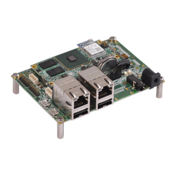
With the 100mmx72mm Pico ITX size, the kit is highly packed with all the necessary on-board connectors to validate the various RZ/G1E CPU interface features. iWave also supports HDMI Add-On Module for RZ/G1E SODIMM development platform to validate expansion connector interfaces of RZ/G1E SODIMM SOM. - Page 9 Serial Communication Interface with FIFO SDIO Secure Digital Input Output SDHI SD Card Host Interface Serial Sound Interface System On Module UART Universal Asynchronous Receiver/Transmitter Universal Serial Bus USB OTG USB On The Go REL1.1 iWave Systems Technologies Pvt. Ltd. Page 9 of 71...
-
Page 10: Terminlogy Description
Note: Signal Type does not include internal pull-ups or pull-downs implemented by the chip vendors and only includes the pull-ups or pull-downs implemented on board. References • Renesas’ RZ/G1E CPU Hardware User Manual REL1.1 iWave Systems Technologies Pvt. Ltd. Page 10 of 71... -
Page 11: Architecture And Design
Since VI1 and MSIOF1 are shared the same SODIMM Edge pins, either one interface only can be connected to the SODIMM Edge in the RZ/G1E SOM. Figure 1: RZ/G1E SODIMM Carrier Board Block Diagram REL1.1 iWave Systems Technologies Pvt. Ltd. Page 11 of 71... -
Page 12: Rz/G1E Sodimm Carrier Board Features
• CAN (CAN1) x 1 Port • SPI (MSIOF1) x 1 Port • PWM x 1 Port 20Pin GPIO Header • SPI (MSIOF2) x 1 • GPIOs x 12 Nos REL1.1 iWave Systems Technologies Pvt. Ltd. Page 12 of 71... - Page 13 ² VI1 and MSIOF1 are shared the same SODIMM Edge pins in RZ/G1E SOM. Hence either one interface only can be used from the SODIMM Edge in the RZ/G1E SOM. By default, VI1 is supported in the SOM REL1.1 iWave Systems Technologies Pvt. Ltd. Page 13 of 71...
-
Page 14: Sodimm Connector
This standard 200-pin robust connector is capable of handling high-speed signals and can be used for size constrained embedded applications. This SODIMM Edge mating connector (J14) is physically located at the top of the board as shown below. Figure 2: SODIMM Connector REL1.1 iWave Systems Technologies Pvt. Ltd. Page 14 of 71... -
Page 15: Table 3: Sodimm Edge Connector Pin Out
Gigabit Ethernet MDI differential pair 3 positive. This pin is connected to RJ45 Magjack J5. GPHY_DTXRXP IO, DIFF Gigabit Ethernet MDI differential pair 4 positive. This pin is connected to RJ45 Magjack J5. REL1.1 iWave Systems Technologies Pvt. Ltd. Page 15 of 71... - Page 16 (J4) LED status pin for 10/100 Ethernet connection. IO, 3.3V CMOS NC in carrier board. GPIO(GP0_0) signal from RZ/G1E CPU is available in this pin. VIN_3V3 O, 3.3V Power Supply Voltage. REL1.1 iWave Systems Technologies Pvt. Ltd. Page 16 of 71...
- Page 17 Note: This pin is connected to second ethernet jack (J4). IO, 3.3V CMOS GPIO(GP1_10) signal from RZ/G1E CPU is available in this pin. Note: This pin is connected to second ethernet jack (J4). REL1.1 iWave Systems Technologies Pvt. Ltd. Page 17 of 71...
- Page 18 NC in carrier board. SCIF3_RXD(GP4_20) signal from RZ/G1E CPU is optionally connected to this pin. IO, 3.3V CMOS NC in carrier board. SCIF3_TXD(GP4_21) signal from RZ/G1E CPU is optionally connected to this pin. REL1.1 iWave Systems Technologies Pvt. Ltd. Page 18 of 71...
- Page 19 This signal is connected to Expansion Header J12 Pin 16. VIN_3V3 O, 3.3V Power Supply Voltage. MSIOF0_SCK(GP4_4) O, 3.3V CMOS General Purpose Input/Output. 10K PU This pin is connected from Touch Controller Interrupt. REL1.1 iWave Systems Technologies Pvt. Ltd. Page 19 of 71...
- Page 20 J6. NC in carrier board. GPIO(GP2_29) signal from RZ/G1E CPU is available in this pin. NC in carrier board. GPIO(GP2_31) signal from RZ/G1E CPU is available in this pin. REL1.1 iWave Systems Technologies Pvt. Ltd. Page 20 of 71...
- Page 21 NC in carrier board. HSCIF2 interface serial data transmitter. This pin is connected to Expansion Header J12 Pin 03. Note: In RZ/G1E SOM same signal is connected to Wi-Fi and Bluetooth Module. REL1.1 iWave Systems Technologies Pvt. Ltd. Page 21 of 71...
- Page 22 O, 3.3V CMOS VIN1 Parallel Camera Data6. ¹ This pin is connected from camera connector SD0_DAT1(GP6_3) IO, 3.3V CMOS SD0 Data1. This pin is connected to Micro SD connector J19. REL1.1 iWave Systems Technologies Pvt. Ltd. Page 22 of 71...
- Page 23 I, 3.3V CMOS Active high Camera Power Down. This pin is connected to camera connector J6. NC in carrier board. GPIO(GP5_0) signal from RZ/G1E CPU is available in this pin. REL1.1 iWave Systems Technologies Pvt. Ltd. Page 23 of 71...
- Page 24 This pin is optionally connected to USB Power switch enable pin through resistor and default not populated. I, 3.3V CMOS NC in carrier board. VIN_3V3 O, 3.3V Power Supply Voltage. REL1.1 iWave Systems Technologies Pvt. Ltd. Page 24 of 71...
- Page 25 Parallel LCD data 11 (Green data3). This pin is connected to LCD connector J23. DU0_DG4(GP2_12) I, 3.3V CMOS Parallel LCD data 12 (Green data4). This pin is connected to LCD connector J23. REL1.1 iWave Systems Technologies Pvt. Ltd. Page 25 of 71...
- Page 26 This pin is connected to CAN1 Transceiver. GPIO(GP4_24) O, 3V CMOS General Purpose Input/Output. This pin is connected from Push button switch SW3 for power On/Off control. VIN_3V3 O, 3.3V Power Supply Voltage. REL1.1 iWave Systems Technologies Pvt. Ltd. Page 26 of 71...
- Page 27 MSIOF2 receive data (Or) General Purpose Input/Output. This pin is connected from GPIO Header J16 Pin 18. 197 JTAG_TCK O, 3.3V CMOS/ JTAG Test Clock. 10K PD This pin is connected from JTAG Header J18. REL1.1 iWave Systems Technologies Pvt. Ltd. Page 27 of 71...
- Page 28 ¹ Since EtherMAC and VI1 are multiplexed in RZ/G1E CPU, either one interface only can be supported in the RZ/G1E SOM. ² Since VI1 and MSIOF1 are shared the same SODIMM Edge pins, either one interface only can be connected to the SODIMM Edge in the RZ/G1E SOM. REL1.1 iWave Systems Technologies Pvt. Ltd. Page 28 of 71...
-
Page 29: Serial Interface Features
Pin Name Description Termination V_DBG_5V I, 5V Power 5V Power. DBUG_USB_DM IO, Diff Debug USB Data negative. DBUG_USB_DP IO, Diff Debug USB Data positive. DBUG_USB_ID No connect. DBUG_USB_GND Power Ground. REL1.1 iWave Systems Technologies Pvt. Ltd. Page 29 of 71... -
Page 30: Data Uart Header
3.3V Supply Voltage. UART_TXD HSCIF1_HTX(GP4_9) I, 3.3V CMOS HSCIF1 Interface Transmit signal. HSCIF1_HRX(GP4_8) UART_RXD O, 3.3V CMOS HSCIF1 Interface Receive signal. UART_RTS# HSCIF1_HRTS(GP4_12) I, 3.3V CMOS HSCIF1 Interface Ready to Send signal. REL1.1 iWave Systems Technologies Pvt. Ltd. Page 30 of 71... -
Page 31: Communication Features
Magjack connector is physically located at the top of the board as shown below. RJ45 Magjack (J5) Figure 5: 100/1000Mbps RJ45 MagJack Note: RZ/G1E CPU’s Ethernet AVB interface doesn’t support 10Mbps speed. REL1.1 iWave Systems Technologies Pvt. Ltd. Page 31 of 71... -
Page 32: 10/100Mbps Ethernet (Optional)
Note: In RZ/G1E SOM EtherMAC and VI1 are multiplexed in RZ/G1E CPU, either one interface only can be supported in the RZ/G1E SOM. By default, VI1 is supported in the SOM. Please contact iWave, if 10/100Mbps Ethernet interface support is required. -
Page 33: Usb2.0 Device
RZ/G1E SODIMM carrier board. This USB Micro AB connector is physically located at the top of the board as shown below. Figure 7: USB2.0 Device Port REL1.1 iWave Systems Technologies Pvt. Ltd. Page 33 of 71... -
Page 34: Usb2.0 Host
(USB1_OVC(GP5_27)) of RZ/G1E CPU. These USB2.0 Type A connectors are physically located at the top of the board as shown below. Figure 8: USB 2.0 Host Ports REL1.1 iWave Systems Technologies Pvt. Ltd. Page 34 of 71... -
Page 35: Microsd Slot
SODIMM Edge connector is connected to Micro SD connector (J19) to support Micro SD storage. The main power to Micro SD connector is 3.3V. This Micro SD connector (J19) is physically located at the bottom of the board as shown below. Figure 9: Micro SD Connector REL1.1 iWave Systems Technologies Pvt. Ltd. Page 35 of 71... -
Page 36: Can Port
Signal Type / Pin Name Description Termination VCC_5V_CAN O, 5V Power 5V Supply Voltage. No Connect. CANL IO, Diff CAN Differential negative. Power Ground. CANH IO, Diff CAN Differential positive. Power Ground. REL1.1 iWave Systems Technologies Pvt. Ltd. Page 36 of 71... -
Page 37: Audio/Video Features
Signal Name Description Termination AGND GND_SIGNAL Power Analog Ground. HP_Left HP_L O, Analog Headphone Output Left. HP_Right HP_R O, Analog Headphone Output Right. I, Analog Microphone Input Signal. No Connect. REL1.1 iWave Systems Technologies Pvt. Ltd. Page 37 of 71... -
Page 38: Rgb Lcd With Touch
Resistive Touch Controller “STMPE811”. Resistive Touch Controller is controlled through RZ/G1E CPU’s I2C5 interface. This RGB LCD connector (J23) is physically located at the bottom of board as shown below. Figure 12: RGB LCD Connector REL1.1 iWave Systems Technologies Pvt. Ltd. Page 38 of 71... -
Page 39: Table 9: 4.3" Rgb Lcd Connector Pin Out
O,3.3V CMOS Display Blue Data 0(LSB). VSS3 Power Ground. DU0_DG7(GP2_15) O,3.3V CMOS Display Green Data 5 (MSB). DU0_DG6(GP2_14) O,3.3V CMOS Display Green Data 4. DU0_DG5(GP2_13) O,3.3V CMOS Display Green Data 3. REL1.1 iWave Systems Technologies Pvt. Ltd. Page 39 of 71... - Page 40 3.3V Power YU/NC I, Analog Touch Panel Output Top. XR/NC I, Analog Touch Panel Output Right. YD/NC I, Analog Touch Panel Output Bottom. XL/NC I, Analog Touch Panel Output Left. REL1.1 iWave Systems Technologies Pvt. Ltd. Page 40 of 71...
-
Page 41: 8Bit Cmos Camera Connector
Compatible Camera Module: Part Number: CN003VEF2052 Description: VGA (640x480 pixel) CMOS camera based on OmniVision’s OV7725 sensor Manufacturer Name: Global Digital Star Limited Manufacturer Web link: http://www.globaldigitalstar.com/ Figure 13: Camera Connector REL1.1 iWave Systems Technologies Pvt. Ltd. Page 41 of 71... -
Page 42: Table 10: Camera Connector Pin Out
Expansion connector J12 pin14 through resistor and default not populated. MSIOF1_SS1/VI1_DATA I, 3.3V CMOS Camera Data1. 1¹ Note: Same pin optionally connected to Expansion connector J12 pin17 through resistor and default not populated. REL1.1 iWave Systems Technologies Pvt. Ltd. Page 42 of 71... -
Page 43: Additional Features
“POR_B” signal in SODIMM Edge connector is directly connected from Reset Push button switch This Reset Push button switch (SW2) is physically located at the top of the board as shown below. Figure 14: Reset Switch REL1.1 iWave Systems Technologies Pvt. Ltd. Page 43 of 71... -
Page 44: Jtag Header
JTAG test mode select. 10K PU Power Ground. I, 3.3V CMOS/ JTAG test clock. 10K PD Power Ground. 10K PD This pin is connected to ground through 10K pull down resistor. Power Ground. REL1.1 iWave Systems Technologies Pvt. Ltd. Page 44 of 71... -
Page 45: Rtc Coin Cell Holder
Table 11: RTC Coin Cell Holder Pin Out Signal Type / Pin Name Description Termination VRTC_3V0 I, 3V Power 3V RTC coin cell power. VRTC_3V0 I, 3V Power 3V RTC coin cell power. Power Ground. REL1.1 iWave Systems Technologies Pvt. Ltd. Page 45 of 71... -
Page 46: Expansion Header
SCIF5 Interface (UART) Transmit Signal. SCIF5_RXD(GP5_1) I, 3.3V CMOS SCIF5 Interface (UART) Receive Signal. SCIF1_TXD(GP4_15) O, 3.3V CMOS SCIF1 Interface (UART) Transmit Signal. SCIF1_RXD(GP4_14) I,3.3V CMOS SCIF1 Interface (UART) Receive Signal. REL1.1 iWave Systems Technologies Pvt. Ltd. Page 46 of 71... - Page 47 RZ/G1E SODIMM Development Platform Hardware User Guide MSIOF1_SS2(GP0_29/MD6) O, 3.3V CMOS SPI Chip select2. TPUTO0_C(GP1_18/MD8) O, 3.3V CMOS PWM0 output Power Ground. Power Ground. REL1.1 iWave Systems Technologies Pvt. Ltd. Page 47 of 71...
-
Page 48: Gpio Header
Parallel LCD data 8 (Green data0) (Or) General Purpose Input/Output. DU0_DG1(GP2_9) IO,3.3V CMOS Parallel LCD data 9 (Green data1) (Or) General Purpose Input/Output. DU0_DR0(GP2_0) IO,3.3V CMOS Parallel LCD data 16 (Red data0) (Or) General Purpose Input/Output. REL1.1 iWave Systems Technologies Pvt. Ltd. Page 48 of 71... - Page 49 MSIOF2 SPI Chip Select. MSIOF2_SCK(GP1_0) O,3.3V CMOS MSIOF2 SPI Clock. MSIOF2_TXD(GP0_31/MD7) O,3.3V CMOS MSIOF2 SPI Master in Slave Out. MSIOF2_RXD(GP0_30) I,3.3V CMOS MSIOF2 SPI Master Out Slave In. Power Ground. Power Ground. REL1.1 iWave Systems Technologies Pvt. Ltd. Page 49 of 71...
-
Page 50: Architecture And Design - Hdmi Add-On Module
CAN Header SCIF_1, SCIF_5 UART Transceiver UART Header Expansion Header HSCIF2 UART Transceiver UART Header I2C1 VCC_5V VCC_1V8 1V8 Regulator VCC_3V3 Figure 19 : HDMI Add On Module Block Diagram REL1.1 iWave Systems Technologies Pvt. Ltd. Page 50 of 71... -
Page 51: Rz/G1E Hdmi Add-On Module Features
Important Note: Since 40pin flip LCD connector, Expansion Header & GPIO Header pins are one to one directly connected from SODIMM carrier board, these connectors pinout information are not included in this section. REL1.1 iWave Systems Technologies Pvt. Ltd. Page 51 of 71... -
Page 52: Hdmi Output
O, TMDS HDMI data0 pair positive. Power Blue Pair Ground. TMDS_D0- D0T- O, TMDS HDMI data0 pair negative. TMDS_CLK+ CLKT+ O, TMDS Display Clock pair positive. Power Clock pair Ground. REL1.1 iWave Systems Technologies Pvt. Ltd. Page 52 of 71... - Page 53 O, 5V CMOS EDID I2C Clock. I2C_SDA IO, 5V CMOS EDID I2C Data. DDC/CEC_GND DDC/CEC_GND Power Ground. O, Power 5V Power Supply. I, 5V TTL HDMI Cable Hot plug detect. REL1.1 iWave Systems Technologies Pvt. Ltd. Page 53 of 71...
-
Page 54: Data Uart Header
SCIF5 Transmit signal. VCC_3V3 VCC_3V3 O, 3.3V Power 3.3V Supply Voltage. RXD_1 SCIF1_RXD(GP4_14) I, RS232 SCIF1 Receive signal. TXD_1 SCIF1_TXD(GP4_15) O, RS232 SCIF1 Transmit signal. RXD_5 SCIF5_RXD(GP5_1) I, RS232 SCIF5 Receive signal. REL1.1 iWave Systems Technologies Pvt. Ltd. Page 54 of 71... -
Page 55: High Speed Data Uart
VCC_3V3 O, 3.3V Power 3.3V Supply Voltage. UART_RXD HSCIF2_HRX(GP0_8) I, RS232 HSCIF2 Receive signal. UART_TXD HSCIF2_HTX(GP0_9) O, RS232 HSCIF2 Transmit signal. UART_RTS HSCIF2_HRTS(GP0_12) I, RS232 HSCIF2 Ready to Send signal. REL1.1 iWave Systems Technologies Pvt. Ltd. Page 55 of 71... -
Page 56: Can1 Header
Description Termination VCC_5V VCC_5V_CAN O, 5V Power 5V Supply Voltage. No Connect. CANL CANL IO, DIFF CAN Differential negative. Power Ground. CANH CANH IO, DIFF CAN Differential positive. Power Ground. REL1.1 iWave Systems Technologies Pvt. Ltd. Page 56 of 71... -
Page 57: Dip Switch
MD18 pin is Connected from CPU, This may effect for boot sequence So before power is supply make sure that 3 bit of SW1 is LOW(OFF). Table 18 DIP Switch Description SW1 Bits SW1 Bit Name GP4_7 High GP0_1O High GP1_13/MD18 High REL1.1 iWave Systems Technologies Pvt. Ltd. Page 57 of 71... -
Page 58: Led
LED Status (D1, D2, D3, D4) in the RZ/G1E HDMI Add-On Module is explained in the following table. Table 19 GPIO Status LED's LED Indication LED’s Name Net Name HIGH GP0_29/MD6 GP1_18/MD8 GP5_7 GP5_8 REL1.1 iWave Systems Technologies Pvt. Ltd. Page 58 of 71... -
Page 59: Technical Specification
Figure 27: Power Jack Table 20: Power Jack Pin Out Signal Type / Signal Name Description Termination 5V, Power Input Supply Voltage. Power Ground. Power Ground. REL1.1 iWave Systems Technologies Pvt. Ltd. Page 59 of 71... -
Page 60: Table 22: Power Input Requirement
Important Note: All carrier board power supplies should be powered ON only after the RZ/G1E CPU is powered ON completely in the RZ/G1E SODIMM SOM. This is to ensure that there is no back voltage (leakage) from any supply on the board towards the RZ/G1E CPU IO pins. REL1.1 iWave Systems Technologies Pvt. Ltd. Page 60 of 71... -
Page 61: Environmental Characteristics
¹ iWave guarantees the component selection for the given operating temperature. To meet this humidity specification, conformal coating needs to be done on the boards. By default, iWave boards doesn’t come with conformal coating. Please contact iWave to support conformal coating. -
Page 62: Mechanical Characteristics
Jack 1 & 2 (23.24mm) followed by RTC Battery Holder (21.9mm) and bottom side maximum height component is JTAG Header (5mm). Please refer the below figure for height details of the RZ/G1E SODIMM Carrier Board. RZ/G1E Figure 29: Mechanical dimension of SODIMM Carrier Board - Side View REL1.1 iWave Systems Technologies Pvt. Ltd. Page 62 of 71... -
Page 63: Rz/G1E Hdmi Daughter Board Mechanical Dimensions
4.3.2 RZ/G1E HDMI Daughter Board Mechanical Dimensions The RZ/G1E HDMI Daughter Board PCB form factor is 40mm x 50mm as shown below. Figure 30 Mechanical dimension of RZ/G1E HDMI Daughter Board - Bottom View REL1.1 iWave Systems Technologies Pvt. Ltd. Page 63 of 71... -
Page 64: Ordering Information
RZ/G1E HDMI Add on Module iW-G22D-DBHD-CA HDMI Add-on Module for RZ/G1E development platform Commercial Note: For Development platform identification purpose, Product part number is pasted as Label with Barcode readable format. REL1.1 iWave Systems Technologies Pvt. Ltd. Page 64 of 71... -
Page 65: Guidelines To Insert The Rz/G1E Sodimm Som Into Carrier Board
When you remove the SOM module, pull away the retention clips (A) on each side of the SOM module. • The module pops up. Grasp the edge of the module (B), and gently pull the module out of the connector Figure 32: RZ/G1E SODIMM Module Removal procedure REL1.1 iWave Systems Technologies Pvt. Ltd. Page 65 of 71... -
Page 66: Hdmi Add-On Module Integration Procedure
Accessory Description Image Quantity HDMI Add-On Module M3 x 14mm Pan Head Screw M3 x 4mm Threaded Metallic Hex Spacer M3 x 10mm Threaded Metallic Hex Spacer 3mm Non-Metallic Flat Washer REL1.1 iWave Systems Technologies Pvt. Ltd. Page 66 of 71... -
Page 67: Figure 33 Pan Head Screw Insertion Top & Bottom View
1. Insert M3x14mm pan head screw from RZ/G1E HDMI Add-On Module top side as shown below. Figure 33 Pan Head Screw insertion top & bottom view 2. Insert 3mm Non-Metallic flat washer into the screw as shown below. Figure 34 Non-Metallic Flat Washer REL1.1 iWave Systems Technologies Pvt. Ltd. Page 67 of 71... -
Page 68: Figure 35 Threaded Metallic Hex Spacer
Press and make sure expansion and GPIO headers of HDMI Add-On module inserted properly into the SODIMM carrier board expansion and GPIO headers. Figure 36 HDMI Add-On Module Insertion top & bottom view REL1.1 iWave Systems Technologies Pvt. Ltd. Page 68 of 71... -
Page 69: Figure 37 Metallic Hex Spacer
6. Connect the 200mm flat cable between SODIMM Carrier board LCD connector(J23) and HDMI Add On Module board LCD Connector(J5) as shown in below. Figure 38 Flat cable Connection top & bottom view REL1.1 iWave Systems Technologies Pvt. Ltd. Page 69 of 71... -
Page 70: Figure 39 Hdmi Cable Insertion
7. Connect the one end of the HDMI cable to the HDMI port of RZ/G1E HDMI Add-On module and another end to the HDMI monitor. Figure 39 HDMI Cable Insertion REL1.1 iWave Systems Technologies Pvt. Ltd. Page 70 of 71... - Page 71 RZ/G1E SODIMM Development Platform Hardware User Guide REL1.1 iWave Systems Technologies Pvt. Ltd. Page 71 of 71...
Need help?
Do you have a question about the iW-RainboW-G22D and is the answer not in the manual?
Questions and answers