Table of Contents
Advertisement
Quick Links
Advertisement
Table of Contents

Related Manuals for iWave iW-RainboW-G27D-Qseven


Summary of Contents for iWave iW-RainboW-G27D-Qseven
- Page 1 8 QM/QP Qseven Development Platform iW-RainboW-G27D-Qseven Quick Start Guide...
- Page 2 Disclaimer Disclaimer iWave Systems reserves the right to change details in this publication iWave Systems reserves the right to change details in this publication including but not limited to any product specification without notice. including but not limited to any product specification without notice.
- Page 3 Introduction Quick Start Guide (QSG) This document is designed for the users to understand iWave’s iW-RainboW-G27D-i.MX 8 QM/QP Qseven SOM Development Platform and start evaluation quickly & easily. Quick Start Guide (QSG) provides the detailed instructions for setting-up the Development Platform from a packed box.
-
Page 4: Environmental Compliance
Safety Do not assemble or use this Development Platform before reading the installation procedure. ESD Protection This Development Platform is ESD sensitive. Handle this product only in accordance with the installation instructions given in the manual. Therefore ESD precautions should be taken care during transport and handling. -
Page 5: Quick Start Steps
Quick Start Steps Step 1 - Unpacking Re move the Development Platform from box and place above the ESD free area. Use anti-static pad/mat with proper grounding to place the Development Platform. Also make sure that, below deliverables are received without any physical damage OTG Cable Development Platform WIFI &... -
Page 6: Bottom View
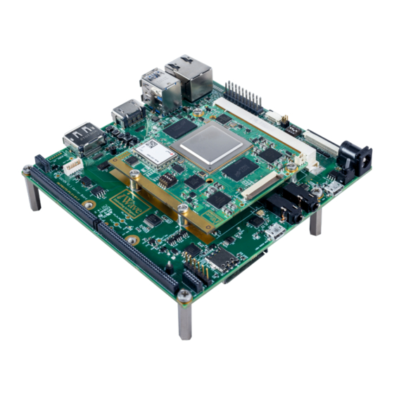
Step 2 - Quick View-SOM Top View 1.MIPI CSI-2 Camera Conn. 2.i.MX 8 QM SoC 3.FAN Conn. 4.Qseven Edge 5.LPDDR4 6.Wi-Fi & BT Module 7.Boot media Switch Bottom View 8.Expansion Conn.2 9.eMMC 10.Micro SD Conn.(Optional) 11.Expansion Conn.1... - Page 7 Step3 - Quick View - Carrier Board Top View 1.Power IN Jack 29 30 31 2.Power switch 3.Q7 MXM Connector 4.USB OTG Connector 5.Audio OUT Jack 6.Audio IN Jack 7.Debug UART Connector 8.Som Expansion Connector 1 9. Som Expansion Connector 2 10.Nano Sim Connector 11.Data UART Header 12.
- Page 8 Step 2 - Read FTP Contents iW-RainboW-G27D Software Release Notes Hardware Binaries Datasheet-UserGuides Datasheet-UserGuides QuickStartGuide Documents SOM-HardwareUserGuide Software UserGuide DevKit-HardwareUserGuide Source code (opt.) DevKit-HardwareUserGuide Heatsink-Datasheet Tool Heatspreader-Datasheet PCB-CAD Files Mechanical Files Patch DevKit Tool Tool Contact For FTP Link : support.ip@iwavesystems.com/mktg@iwavesystems.com Before moving to next step, one must go through all the documents including Hardware User Guides and get familiar about iW-RainboW-G27D i.MX 8 QM/QP SOM &...
-
Page 9: Step 5- Setting-Up
Step 5- Setting-Up On Board Switch Setting Make sure On-Board Switch (SW1) set properly as shown in below image. (0 1 0 0) Note : 0 - OFF 1 - ON SW5- Boot Selection Switch Note : Refer the Hardware User Guide for detailed information of each switch. -
Page 10: Debug Port Setting
Debug Port Setting Connect Type-A end of USB cable to PC and Micro-B end of USB cable to Development Platform's Debug USB Micro-AB Connector (J3) as shown below. Install the driver for Debug Port in Host PC/Laptop using the below link. https://ftdichip.com/drivers/vcp-drivers/ Setup the Debug Terminal parameters. - Page 11 1. Do not try to connect any other power supply other than supplied along with the Development Kit. 2. Do not plug or remove the i.MX 8 QM/QP Qseven SOM from carrier board with live power. 3. Contact iWave if power LEDs are not glowing.
- Page 12 Press any key in terminal immediately to see the command prompt of the Boot loader or wait until OS boots. iWave supports below mentioned Operating System Releases for iW- RainboW-G27D i.MX 8 QM/QP Qseven Development Platform. Linux 5.9.51 (or higher) Android Pie 9.0 (or higher)
- Page 13 Command Prompt (Android) Linux Home Screen Android Home Screen...
- Page 14 Product Name : NXP’s i.MX 8 QM/QP SoC Processor : 4GB LPDDR4* : Industrial Motor Control, Sensor Application Fusion, Industrial IoT, Complex consumer, medical, and industrial embedded computing applications * RAM size is expandable. Contact iWave team for further details...
-
Page 15: Need More Help
Warranty & RMA Warranty & RMA Warranty support for Hardware: 1 Year from iWave or iWave's EMS partner. Warranty support for Hardware: 1 Year from iWave or iWave's EMS partner. Warranty support for Hardware: 1 Year from iWave or iWave's EMS partner. - Page 16 Headquarters: INDIA JAPAN UNITED STATES iWave Systems Tech. Pvt. Ltd. iWave Japan, Inc. iWave US 7/B, 29th Main, BTM Layout 2nd Stage, 8F-B, Kannai Sumiyoshi Building, 1692 Westmont Ave., Campbell, Bengaluru-560076,India. 3-29, Sumiyoshi-cho, Naka-ku, Yokohama, CA95008 USA Ph: +91-80-26683700, 26781643 Kanagawa, Japan.
Need help?
Do you have a question about the iW-RainboW-G27D-Qseven and is the answer not in the manual?
Questions and answers
How do you boot from power
To boot the iWave iW-RainboW-G27D-Qseven from power:
1. Connect the 12V power supply plug to the power connector (J4) on the Development Platform.
2. Switch ON the power supply.
3. The power LEDs on the i.MX 8 QM/QP Qseven SOM and carrier board should glow.
4. Boot messages will then appear in the debug terminal on the connected PC or laptop.
Note: Do not use a power supply other than the one provided with the Development Kit. Do not connect or disconnect the SOM with the power on.
This answer is automatically generated