iWave iW-RainboW-G34D Hardware User's Manual
I.mx 8m mini sodimm development platform
Hide thumbs
Also See for iW-RainboW-G34D:
- Hardware user's manual (73 pages) ,
- Quick start manual (17 pages) ,
- Hardware user's manual (62 pages)

Subscribe to Our Youtube Channel
Related Manuals for iWave iW-RainboW-G34D


Summary of Contents for iWave iW-RainboW-G34D
- Page 1 8M Mini SODIMM Development Platform Hardware User Guide iW-RainboW-G34D i.MX 8M Mini SODIMM Development Platform Hardware User Guide REL1.0 iWave Systems Technologies Pvt. Ltd. Page 1 of 55...
- Page 2 If you are not the intended recipient (or authorized to receive for the recipient), you are hereby notified that any disclosure, copying distribution or use of any of the information contained within this document is STRICTLY PROHIBITED. Thank you. “iWave Systems Tech. Pvt. Ltd.” REL1.0 iWave Systems Technologies Pvt.
- Page 3 No warranty of accuracy is given concerning the contents of the information contained in this publication. To the extent permitted by law no liability (including liability to any person by reason of negligence) will be accepted by iWave Systems, its subsidiaries or employees for any direct or indirect loss or damage caused by omissions from or inaccuracies in this document.
-
Page 4: Table Of Contents
TECHNICAL SPECIFICATION.......................... 49 Electrical Characteristics ..........................49 3.1.1 Power Input Requirement ........................... 49 Environmental Characteristics ........................51 3.2.1 Environmental Specification ........................51 3.2.2 RoHS Compliance ............................51 3.2.3 Electrostatic Discharge ..........................51 REL1.0 iWave Systems Technologies Pvt. Ltd. Page 4 of 55... - Page 5 APPENDIX ..............................54 Guidelines to insert the i.MX 8M Mini SODIMM SOM into Carrier Board ............. 54 Guidelines to remove the i.MX 8M Mini SODIMM SOM from Carrier board ..........54 REL1.0 iWave Systems Technologies Pvt. Ltd. Page 5 of 55...
- Page 6 Figure 23: Mechanical dimension of i.MX 8M Mini Carrier Board - Side View ................. 52 Figure 24: i.MX 8M Mini SODIMM Module Insertion procedure ..................... 54 Figure 25: i.MX 8M Mini SODIMM Module Removal procedure ....................54 REL1.0 iWave Systems Technologies Pvt. Ltd. Page 6 of 55...
- Page 7 Table 14: GPIO Header Pin Out ..............................48 Table 15: Power Jack Pin Out ..............................49 Table 16: Power Input Requirement ............................50 Table 17: Environmental Specification ............................. 51 Table 18: Orderable Product Part Numbers ..........................53 REL1.0 iWave Systems Technologies Pvt. Ltd. Page 7 of 55...
-
Page 8: Introduction
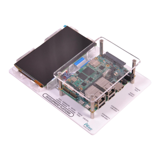
The SODIMM is a versatile small form factor computer Module targeting applications that require low power, low cost and high performance. iW-RainboW-G34D Development Platform comes with SODIMM Carrier, i.MX 8M Mini based SODIMM SOM along with 5.5- inch Capacitive Touch Display. The development board can be used for quick prototyping of various applications targeted by the i.MX 8M Mini processor. - Page 9 SDIO Secure Digital Input Output SDHI SD Card Host Interface System On Module Serial Sound Interface UART Universal Asynchronous Receiver/Transmitter Universal Serial Bus USB OTG USB On The Go Voltage REL1.0 iWave Systems Technologies Pvt. Ltd. Page 9 of 55...
-
Page 10: Terminlogy Description
Not Connected Note: Signal Type does not include internal pull-ups or pull-downs implemented by the chip vendors and only includes the pull-ups or pull-downs implemented on board. References • IMX8MMIEC_Rev_x.pdf REL1.0 iWave Systems Technologies Pvt. Ltd. Page 10 of 55... -
Page 11: Architecture And Design
This section provides detailed information about the i.MX 8M Mini SODIMM development platform carrier board features with high level block diagram and detailed information about each block. i.MX 8M Mini SODIMM Development Platform Block Diagram iW-RainboW-G34D-i.MX 8M Mini SODIMM SOM Development Kit Block Diagram SODIMM To On-Board Power PCB Edge Connector Circuit &... -
Page 12: I.mx 8M Mini Sodimm Development Platform Features
Data UART x 2 Port (One is Optional) • PWM x 1 Port • ECSPI x 2 Port (One is Optional) 20Pin GPIO Header • ECSPI x 1 • GPIOs REL1.0 iWave Systems Technologies Pvt. Ltd. Page 12 of 55... - Page 13 UART1 interface cannot be supported in 20Pin Expansion Connector of SODIMM carrier card. i.MX 8M Mini CPU’s MIPI CSI and MIPI DSI interface is validated with iWave’s SODIMM MIPI daughter Board where signals are connected from MIPI CSI FPC Connector (40Pin) & MIPI DSI Connector (20Pin) of SODIMM carrier card. For more information on SODIMM MIPI daughter board please contact iWave.
-
Page 14: Sodimm Edge Connector
200-pin robust connector is capable of handling high-speed signals and can be used for size constrained embedded applications. This SODIMM Edge mating connector (J14) is physically located at the top of the board as shown below. Figure 2: SODIMM Connector REL1.0 iWave Systems Technologies Pvt. Ltd. Page 14 of 55... -
Page 15: Table 3: Sodimm Edge Connector Pin Out
SODIMM Edge. Default not Populated VIN_3V3 I, 3.3V Power Supply Voltage. Power Ground. GPHY2_ACTIVITY_LED1* O, 3.3V CMOS Second Ethernet Activity status LED. Note: This Signal is Optionally Connected to SODIMM Edge. Default not Populated REL1.0 iWave Systems Technologies Pvt. Ltd. Page 15 of 55... - Page 16 Note: This Signal is Optionally Connected to SODIMM Edge. Default not Populated GPHY2_DTXRXP* IO, DIFF Second Gigabit Ethernet differential pair 4 positive. Note: This Signal is Optionally Connected to SODIMM Edge. Default not Populated REL1.0 iWave Systems Technologies Pvt. Ltd. Page 16 of 55...
- Page 17 ECSPI2_MISO ECSPI2_MISO/A8 I, 3.3V CMOS SPI2 Master Input Slave Output. GPIO_CLK(SAI5_MCLK) SAI5_MCLK/AD15 O, 3.3V CMOS Master Clock for Audio codec. Power Ground. ECSPI2_SCLK ECSPI2_SCLK/E6 O, 3.3V CMOS SPI2 clock signal. REL1.0 iWave Systems Technologies Pvt. Ltd. Page 17 of 55...
- Page 18 I, 3.3V Power Supply Voltage. SAI5_TX_SYNC(SAI5_RXD SAI5_RXD1/AC14 O, 3.3V CMOS SAI5 Transmitter Frame Sync SAI5_TX_BCLK(SAI5_RXD2 SAI5_RXD2/AD13 O, 3.3V CMOS SAI5 Transmitter Bit Clock SAI5_RX_BCLK(SAI5_RXC) SAI5_RXC/AC15 I, 3.3V CMOS SAI5 Receiver Bit Clock. REL1.0 iWave Systems Technologies Pvt. Ltd. Page 18 of 55...
- Page 19 SD Clock Line. CMOS 110 NC 111 SD2_DATA1 SD2_DATA1/AB24 IO, 3.3V/1.8V SD data 1 line. CMOS 112 SD2_DATA2 SD2_DATA2/V24 IO, 3.3V/1.8V SD data 2 line CMOS 113 GND Power Ground. REL1.0 iWave Systems Technologies Pvt. Ltd. Page 19 of 55...
- Page 20 O, PCIe/ PCIe Transmit Negative. 0.1uF AC Coupled 130 PCIE_RXN PCIE_RXN_N/A19 I, PCIe PCIe Receive Negative 131 GND Power Ground. 132 GPIO_RESET(GPIO5_2) SAI3_TXD/AF6 O, 3.3V CMOS General Purpose Reset Output. REL1.0 iWave Systems Technologies Pvt. Ltd. Page 20 of 55...
- Page 21 SAI1 Receiver Data 4. 100K PD Note: These signals are also used for i.MX8M Mini CPU boot media setting on SOM and so no external loads or pull-up/pull-down resistors to be REL1.0 iWave Systems Technologies Pvt. Ltd. Page 21 of 55...
- Page 22 163 SAI1_TXD4 SAI1_TXD4/AG22 O, 3.3V CMOS SAI1 Transmit Data 4. 100K PD Note: These signals are also used for i.MX8M Mini CPU boot media setting on SOM and so no REL1.0 iWave Systems Technologies Pvt. Ltd. Page 22 of 55...
- Page 23 Note: These signals are also used for i.MX8M Mini CPU boot media setting on SOM and so no external loads or pull-up/pull-down resistors to be connected to these pins which will change the boot configuration REL1.0 iWave Systems Technologies Pvt. Ltd. Page 23 of 55...
- Page 24 SPI3 clock signal. 190 USB2_DN USB2_DN/A23 IO, USB USB2 OTG High Speed Data Positive. 191 JTAG_TDO JTAG_TDO/E26 O, 3.3V CMOS JTAG Test Data Output. 192 VIN_3V3 I, 3.3V Power Supply Voltage. REL1.0 iWave Systems Technologies Pvt. Ltd. Page 24 of 55...
- Page 25 JTAG Test Clock. 198 GND Power Ground. 199 JTAG_TMS JTAG_TMS/F27 I, 3.3V CMOS JTAG Test Mode Select. 200 USB_OTG1_VBUS I, Power 5V USB1 VBUS Power. * Optional feature, by default not supported. REL1.0 iWave Systems Technologies Pvt. Ltd. Page 25 of 55...
-
Page 26: Serial Interface Features
Pin Name Description Termination V_DBG_5V I, 5V Power 5V Power. DBUG_USB_DM IO, Diff Debug USB Data negative. DBUG_USB_DP IO, Diff Debug USB Data positive. DBUG_USB_ID No connect. DBUG_USB_GND Power Ground. REL1.0 iWave Systems Technologies Pvt. Ltd. Page 26 of 55... -
Page 27: Data Uart Header
3.3V Supply Voltage. UART_TXD UART2_TX(SAI3_TXC) O, 3.3V CMOS UART2 Interface Transmit signal. UART_RXD UART2_RX(SAI3_TXFS) I, 3.3V CMOS UART2 Interface Receive signal. UART_RTS# UART2_RTS_B(SAI3_RXD) I, 3.3V CMOS UART2 Interface Ready to Send signal. REL1.0 iWave Systems Technologies Pvt. Ltd. Page 27 of 55... -
Page 28: Communication Features
(Yellow) and Link/Activity (Green) LED indications on RJ45 Magjack connector. This RJ45 Magjack connector is physically located at the top of the board as shown below. Figure 5: 10/100/1000Mbps RJ45 MagJack -1 REL1.0 iWave Systems Technologies Pvt. Ltd. Page 28 of 55... -
Page 29: 10/100/1000 Mbps Ethernet-2 (Optional)
Note: In i.MX 8M Mini SOM, PCIe lane signals are optionally to connected to PCIe to Ethernet controller and by default connected to SODIMM PCB Edge Connector. So either one interface can be supported in the i.MX 8M Mini SOM. Please contact iWave, if 10/100/1000Mbps Ethernet interface support is required in 2 Ethernet Port. -
Page 30: Usb2.0 Device
8M Mini SODIMM carrier board. This USB Micro AB connector is physically located at the top of the board as shown below. Figure 7: USB2.0 Device Port REL1.0 iWave Systems Technologies Pvt. Ltd. Page 30 of 55... -
Page 31: Usb2.0 Host
SODIMM Connector. These USB2.0 Type A host connectors are physically located at the top of the board as shown below. Figure 8: USB 2.0 Host Ports REL1.0 iWave Systems Technologies Pvt. Ltd. Page 31 of 55... -
Page 32: Microsd Slot
SODIMM Edge connector is connected to Micro SD connector (J19) to support Micro SD storage. The main power to Micro SD connector is 3.3V. This Micro SD connector (J19) is physically located at the bottom of the board as shown below. Figure 9: Micro SD Connector REL1.0 iWave Systems Technologies Pvt. Ltd. Page 32 of 55... -
Page 33: High Speed Interfaces
O, 3.3V Power 3.3V Power Supply. VCC_PCIe3V3 VCC_PCIe3V3 COEX1 Power Ground. COEX2 VCC_1V5_3G O, 1.5V Power Supply for 3G VCC_1V5_3G CLKREQ# UIM_PWR Power Ground. UIM_DATA PCIE_REFCLK_DM(CLK1_N) PCIE_REFCLK_DM O, DIFF PCIe reference clock negative. REL1.0 iWave Systems Technologies Pvt. Ltd. Page 33 of 55... - Page 34 Ground VCC_PCIe3V3 O, 3.3V 3.3V Power Supply. VCC_PCIe3V3 LED Enable. LED_WWAN# I, 3.3V CMOS Connected to green LED D15 and default populated. Power Ground LED_WLAN# I, 3.3V CMOS LED Enable. REL1.0 iWave Systems Technologies Pvt. Ltd. Page 34 of 55...
- Page 35 I, 3.3V CMOS Connected to green LED D17 and default populated. RSVD1 VCC_1V5_3G O, 1.5V Power Supply for 3G VCC_1V5_3G RSVD2 Power Ground RSVD3 VCC_PCIe3V3 O, 3.3V Power 3.3V Power Supply. VCC_PCIe3V3 REL1.0 iWave Systems Technologies Pvt. Ltd. Page 35 of 55...
-
Page 36: Audio/Video Features
Pin Name Signal Name Description Termination AGND Power Analog Ground. HP_Left HP_L O, Analog Headphone Output Left. HP_Right HP_R O, Analog Headphone Output Right. I, Analog Microphone Input Signal. No Connect. REL1.0 iWave Systems Technologies Pvt. Ltd. Page 36 of 55... -
Page 37: Additional Features
8M Mini SODIMM development platform. Figure 12: MIPI CSI Camera FPC Connector Note: The OV5640 MIPI Camera is supported in SODIMM MIPI daughter board. For more information on daughter board please contact iWave. REL1.0 iWave Systems Technologies Pvt. Ltd. Page 37 of 55... -
Page 38: Table 8: 40 Pin -Mipi Csi Camera Fpc Connector
SAI1 Receive 7. VSYNC SAI1_TXFS O,3.3V CMOS SAI1 Transmit sync. GPIO1_8 O,3.3V CMOS General Purpose Input/Output. ROTATE/NC2 SHUT/STB/NC3 VSS6 Power Ground. VCC_3V3 O, 3.3V Power 3.3V Supply Voltage. YU/NC XR/NC YD/NC REL1.0 iWave Systems Technologies Pvt. Ltd. Page 38 of 55... -
Page 39: Mipi Dsi Display Interface Connector
Figure 13: MIPI DSI display interface Connector Note: The 5.49inch AMOLED Display with Capacitive touch panel is supported in SODIMM MIPI daughter board. For more information on daughter board please contact iWave. REL1.0 iWave Systems Technologies Pvt. Ltd. Page 39 of 55... -
Page 40: Table 9: 20 Pin -Mipi Dsi Connector Pin Out
MIPI_DSI Clock Negative. LVDS0_CLK_P MIPI_DSI_CLK_P O, DIFF MIPI_DSI Clock Positive. Power Ground. LVDS0_TX3_N MIPI_DSI_DATA3_N O, DIFF MIPI_DSI DATA Lane3 Negative. LVDS0_TX3_P MIPI_DSI_DATA3_P O, DIFF MIPI_DSI DATA Lane3 Positive. Power Ground. Power Ground. REL1.0 iWave Systems Technologies Pvt. Ltd. Page 40 of 55... -
Page 41: Boot Mode Switch
8M Mini eFUSE settings. In this mode, i.MX 8M Mini boot Serial Downloader device can be programmed through Mode its USB OTG interface using UUU Tool. REL1.0 iWave Systems Technologies Pvt. Ltd. Page 41 of 55... -
Page 42: Reset Switch
SODIMM Edge connector is directly connected from Power On/Off Push button switch which is physically located at the top of the board as shown below. Figure 16: Power On/Off Switch REL1.0 iWave Systems Technologies Pvt. Ltd. Page 42 of 55... -
Page 43: Jtag Header
I, 3.3V CMOS JTAG test data Input. Power Ground. JTAG_TMS I, 3.3V CMOS/ JTAG test mode select. 10K PU Power Ground. JTAG_TCK I, 3.3V CMOS/ JTAG test clock. 10K PD Power Ground. REL1.0 iWave Systems Technologies Pvt. Ltd. Page 43 of 55... - Page 44 Power Ground. PWRON_B I,3.3V CMOS/ Reset Signal. 10K PU Power Ground. No Connect. Power Ground. 10K PD This pin is connected to ground through 10K pull down resistor. Power Ground. REL1.0 iWave Systems Technologies Pvt. Ltd. Page 44 of 55...
-
Page 45: Rtc Coin Cell Holder
Table 12: RTC Coin Cell Holder Pin Out Signal Type / Pin Name Description Termination VRTC_3V0 I, 3V Power 3V RTC coin cell power. VRTC_3V0 I, 3V Power 3V RTC coin cell power. Power Ground. REL1.0 iWave Systems Technologies Pvt. Ltd. Page 45 of 55... -
Page 46: Expansion Header
Please refer SOM User Manual for IOMUX Confiuation. SAI1_RXD6¹ I, 3.3V CMOS SAI1 Receive Signal 6. Note: This signal is also used for CPU boot media setting on i.MX 8M Mini SODIMM SOM REL1.0 iWave Systems Technologies Pvt. Ltd. Page 46 of 55... -
Page 47: Gpio Header
8M Mini CPU. 4 GPIOs,SAI1 signals,ECSPI interface signals pins SODIMM Edge is directly connected to this GPIO Header.This GPIO Header (J16) is physically located at the top of the board as shown below. Figure 20: GPIO Header REL1.0 iWave Systems Technologies Pvt. Ltd. Page 47 of 55... -
Page 48: Table 14: Gpio Header Pin Out
¹Important Note: These signals are also used for CPU boot media setting on i.MX 8M Mini SODIMM SOM and no external loads or pull-up/pull-down resistors to be connected to these pins which will change the boot configuration. REL1.0 iWave Systems Technologies Pvt. Ltd. Page 48 of 55... -
Page 49: Technical Specification
1.35mm and an outer dimension of 3.5mm. This connector is physically placed at the top of the board as shown below. Figure 21: Power Jack Table 15: Power Jack Pin Out Signal Type / Signal Name Description Termination 5V, Power Input Supply Voltage. Power Ground. Power Ground. REL1.0 iWave Systems Technologies Pvt. Ltd. Page 49 of 55... -
Page 50: Table 16: Power Input Requirement
OFF if SOM is powered OFF. This is to ensure that there is no back voltage (leakage) from any supply on the board towards the i.MX 8M Mini CPU IO pins. REL1.0 iWave Systems Technologies Pvt. Ltd. Page 50 of 55... -
Page 51: Environmental Characteristics
3.2.3 Electrostatic Discharge iWave’s i.MX 8M Mini SODIMM Carrier Board is sensitive to electro static discharge and so high voltages caused by static electricity could damage some of the devices on board. It is packed with necessary protection while shipping. Do not open or use the board except at an electrostatic free workstation. -
Page 52: Mechanical Characteristics
(5mm). Please refer the below figure for height details of the i.MX 8M Mini SODIMM Carrier Board. Figure 23: Mechanical dimension of i.MX 8M Mini Carrier Board - Side View REL1.0 iWave Systems Technologies Pvt. Ltd. Page 52 of 55... -
Page 53: Ordering Information
Platform with 1GB LPDDR4, 8GB eMMC flash, Commercial 1xEthernet, with 5.5" Capacitive touch LCD display. Note: For Development platform identification purpose, Product part number is pasted as Label with Barcode readable format. REL1.0 iWave Systems Technologies Pvt. Ltd. Page 53 of 55... -
Page 54: Appendix
• The module pops up. Grasp the edge of the module (B), and gently pull the module out of the connector Figure 25: i.MX 8M Mini SODIMM Module Removal procedure REL1.0 iWave Systems Technologies Pvt. Ltd. Page 54 of 55... - Page 55 8M Mini SODIMM Development Platform Hardware User Guide REL1.0 iWave Systems Technologies Pvt. Ltd. Page 55 of 55...
Need help?
Do you have a question about the iW-RainboW-G34D and is the answer not in the manual?
Questions and answers