Kessel Ecolift XL Instructions For Installation, Operation And Maintenance
Backwater lifting station
Hide thumbs
Also See for Ecolift XL:
- Instructions for installation, operation and maintenance (240 pages) ,
- Installation and operating instructions manual (112 pages) ,
- Installation and operating instructions manual (132 pages)
Table of Contents
Advertisement
Available languages
Available languages
Quick Links
ANLEITUNG FÜR EINBAU, BETRIEB UND WARTUNG
KESSEL Rückstauhebeanlage Ecolift XL
Installation
der Anlage wurde durchgeführt von Ihrem Fachbetrieb:
Name/Unterschrift
Stand 2015/03
Inbetriebnahme
Datum
Einweisung
Ort
Produktvorteile
Für fäkalienfreies und
-haltiges Abwasser
Reduktion von
Pumplaufzeiten
durch Nutzung des
Kanalgefälles
Optional mit Dichtflansch
zum Einbau in WU-Beton
Schaltgerät mit
Selbstdiagnosesystem
und Batteriepufferung
USB-Schnittstelle zum
Auslesen des Logbuches
Stempel Fachbetrieb
D
Seite 1
GB
Page 45
F
Page 89
I Pagina 133
NL Pagina 177
PL Strona 221
Sach-Nr. 010-694
Advertisement
Chapters
Table of Contents

Related Manuals for Kessel Ecolift XL


Summary of Contents for Kessel Ecolift XL
- Page 1 ANLEITUNG FÜR EINBAU, BETRIEB UND WARTUNG Seite 1 KESSEL Rückstauhebeanlage Ecolift XL Page 45 Page 89 I Pagina 133 NL Pagina 177 PL Strona 221 Produktvorteile Für fäkalienfreies und -haltiges Abwasser Reduktion von Pumplaufzeiten durch Nutzung des Kanalgefälles Optional mit Dichtflansch zum Einbau in WU-Beton Schaltgerät mit...
-
Page 2: Table Of Contents
Inhaltsverzeichnis Einleitung Produktbeschreibung, allgemein ..................4 Allgemeine Hinweise zu dieser Betriebs- und Wartungsanleitung ........5 Funktionsprinzip ........................ 6 1.3.1 Funktionsprinzip Ecolift XL ....................6 1.3.2 Funktionsprinzip niedrigster Einbau .................. 6 Typenschild ........................7 Lieferumfang ........................8 1.5.1 Variante Ecolift ........................8 Baugruppen und Funktionsmerkmale ................ - Page 3 3.9.3 Niveaufühler und Drucksensoren anschließen ..............20 3.10 Erstinbetriebnahme ......................21 3.10.1 Schaltgerät initialisieren ....................21 3.10.2 KESSEL Tele-Control-Modem für Fehlermeldungen einrichten ........22 3.10.3 Anpassung der Schaltpunkte für Lufteinperlung ............... 22 3.10.4 Funktionskontrolle ......................22 Betrieb Einschalten ........................23 Display, Anzeigen / Informationen ..................
-
Page 4: Einleitung
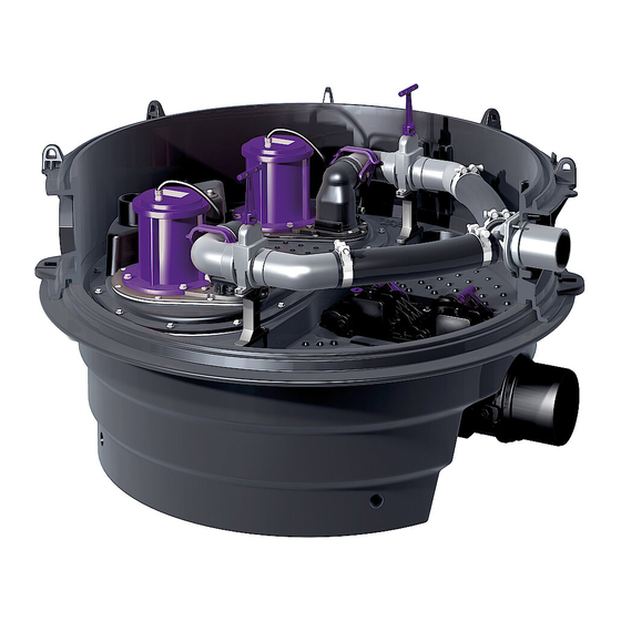
Haben Sie Fragen? Wir freuen uns auf Ihre Kontaktaufnahme. Produktbeschreibung, allgemein Die KESSEL Rückstauhebeanlage Ecolift XL (im folgenden Rückstauhebeanlage benannt) ist für das Abpumpen von fäkalienfreiem und fäkalienhaltigem Abwasser vorgesehen. In den Abwasserbehälter sind die Baugruppen für die Pumpen, den Drucksensor, die motorisch angetriebene Rückstauklappe sowie die Pendelklappe (Notverschluss) eingebaut. -
Page 5: Allgemeine Hinweise Zu Dieser Betriebs- Und Wartungsanleitung
Einleitung Allgemeine Hinweise zu dieser Betriebs- und Wartungsanleitung Diese Betriebs- und Wartungsanleitung ist nur in Verbindung der Betriebs- und Montageanleitung des Schaltgeräts Comfort PLUS - Control Unit (Sach-Nr. 010-700) vollständig. Verwendete Symbole und Legenden <1> Hinweis im Text auf eine Legendennummer in einer Abbildung Bezug auf eine Abbildung •... -
Page 6: Funktionsprinzip
Einleitung Funktionsprinzip 1.3.1 Funktionsprinzip Ecolift XL Abb. [1] 1.3.2 Funktionsprinzip niedrigster Einbau 6 / 264 03/2015... -
Page 7: Typenschild
Einleitung Typenschild Informationen auf dem Typenschild der Rückstauhebeanlage Bezeichnung der Anlage Materialnummer Anschlussspannung und Anschlussfrequenz Hydraulische Daten Allgemeine Daten Seriennummer Fertigungsdatum Revisionsstand Normenbezeichung Auftragsnummer Abb. [2] Informationen auf dem Typenschild des Schaltgerätes Bezeichnung des Schaltgerätes Material-Nummer des Schaltgerätes Anschlussspannung und Anschlussfrequenz Stromaufnahmebereich Schutzart (IP) Seriennummer des Schaltgerätes... -
Page 8: Lieferumfang
Einleitung Lieferumfang Anlage bzw. alle Lieferkomponenten auf evtl. Mängel überprüfen 1.5.1 Variante Ecolift Schaltgerät FKA Standard für Redundanzverschluss Ecolift XL mit eigener Montageanleitung* Kleinkompressor zur Lufteinperlung mit Montageanleitung* Montageanleitung Schaltgerät Comfort PLUS mit eigener Montageanleitung Anschlussplan, im Gehäusedeckel des Schaltgerätes Befestigungsmaterial für Schaltgerät Bohrschablone für Schaltgerät Anlagenbehälter (Bodenelement des Schachtsystems) -
Page 9: Baugruppen Und Funktionsmerkmale
Anschluss für Entlüftungsleitung Schachtsystems Schachtsystem, bestehend aus verschiedenen Optische Sonde Redundanzverschluss* Elementen (ohne Abbildung) Typenschild Optische Sonde Rückstauklappe Abwasserpumpe(n*) Absperrschieber Druckleitung Schaltgerät Redundanzverschluss Ecolift XL* Zulaufstutzen ** Motor Redundanzverschluss* Motor Rückstauklappe* * Option ** DN150, oder DN200 03/2015 9 / 264... -
Page 10: Sicherheit
Sicherheit Sicherheit Bestimmungsgemäße Verwendung Die Rückstauhebeanlage dient als Entwässerungsanlange für fäkalienhaltiges und –freies, häusliches und gewerbliches Abwasser, montiert in einem begehbaren KESSEL-Schachtsystem, unterschiedlicher Höhe und Ausprägung. Personalauswahl und -qualifikation Personen, die die Rückstauhebeanlage montieren, müssen – mindestens 18 Jahre alt sein. -
Page 11: Gefahren, Die Vom Produkt Ausgehen
Sicherheit Gefahren, die vom Produkt ausgehen 2.4.1 Gefahr durch besondere Örtlichkeit / Umgebungsbedingungen Gefahr durch giftige und gesundheitsgefährdende Dämpfe, Gase und Stoffe (z. B. Bakterien, Viren). Befindet sich die Rückstauhebeanlage in einem Schacht, sind darin notwendige Arbeiten ausschließlich durch Fachpersonal (Siehe 2.2) durchzuführen. 2.4.2 Gefahr durch elektrischen Schlag bei abgeschraubtem Stecker Am Schaltgerät (nur 230V-Ausführung) besteht die Gefahr eines elektrischen Stromschlags, wenn einer der Stecker für die Stromversorgung der Pumpen demontiert ist. -
Page 12: Gefahr Durch Hitze
Sicherheit 2.4.7 Gefahr durch Hitze Gefahr von Verbrennungen beim Berühren heißer Oberflächen. Abwasserpumpen entwickeln bei längerem Lauf eine hohe Temperatur an der Gehäuseoberfläche. Schutzausrüstung (Handschuhe) tragen oder Pumpen entsprechend abkühlen lassen. 2.4.8 Gefahr durch unerwartetes Anlaufen einer Pumpe Ist die Rückstauhebeanlage nicht vom Netz getrennt, kann jede Pumpe unvermittelt anlaufen. Pumpen ausschließlich durch Fachpersonal und bei freigeschalter sowie gegen unbeabsichtigtes Wiedereinschalten abgesicherter Ablage ausbauen. -
Page 13: Montage
4. Erstinbetriebnahme (Kapitel 3.9). Sicherstellen, dass die unter 1. genannten Arbeiten vollständig abgeschlossen sind. Behälter fixieren Der freiaufgestellte Ecolift XL-Behälter ist umlaufend mit herkömmlichen Winkelverbindern zu fixieren. Diese werden jeweils mit 4 Stück 4 x 35 mm Spax-Schrauben seitlich in den Behälter geschraubt. Die Fixierung nach unten ist je nach Bodenbeschaffenheit auszuführen. -
Page 14: Abwasserpumpe(N) Montieren
Montage Abwasserpumpe(n) montieren Abwasserpumpe(n) mit den Schrauben <1> befestigen (Anzugsmoment 7Nm). Die Druckleitung ist in einem geschweißtem PE-Rohr, bei Pumpe SPF 4500 zusätzlich in einen Druckentspannungs- schacht auszuführen. Abb. [8] Alarmsensor montieren • Alarmsensor (Optische Sonde) <15> in die Aufnahme <38> montieren (rote Kabelmarkierung). -
Page 15: Optische Sonde An Rückstauklappe(N) Montieren
Montage Optische Sonde an Rückstauklappe(n) montieren Je nach Ausführung befindet sich eine oder zwei optische Sonden für die Rückstauerkennung im Lieferumfang. Diese werden wie folgt montiert: Kabelmarkierung Funktion keine Rückstauklappe Gelb Redundanzverschluss Sonde Rückstauklappe montieren • Optische Sonde <1> an Rückstauklappe <A und optional B> befestigen, dazu: •... -
Page 16: Antriebsmotor Rückstauklappe(N) Montieren
(Position 14 in Abb. [9]) und in Abb. [10]) 3.8.1 Haupt-Schaltgerät befestigen / anschließen Schaltgerät Comfort PLUS gemäß der dem Schaltgerät beiliegenden Anleitung montieren. 3.8.2 KESSEL Tele-Control-Modem montieren (Option) KESSEL Tele-Control-Modem gemäß der diesem Schaltgerät beiliegenden Anleitung montieren. 16 / 264 03/2015... -
Page 17: Schaltgerät Redundanzverschluss Befestigen / Anschließen
Am Haupt-Schaltgerät (Comfort PLUS) <1> eine Kabeldurchführung neben der Kabeldurchführung <g> montieren. • Elektrischen Anschluss zwischen Schaltgerät FKA Standard <4> und dem Haupt-Schaltgerät <1> herstellen, dazu: Das am Schaltgerät Redundanzverschluss Ecolift XL vormontierte Anschlusskabel <2> am Haupt-Schaltgerät wie folgt anschließen: Haupt-Schaltgerät Kabelfarben des Klemmen <3>... -
Page 18: Elektrische Anschlüsse Und Anschlüsse Niveausensoren Herstellen
Montage Elektrische Anschlüsse und Anschlüsse Niveausensoren herstellen Sicherstellen, dass das Schaltgerät während den Montagearbeiten von der Spannungsversorgung getrennt ist. Gefahr von elektrischem Schlag bei unbeabsichtigten Berühren abgeschraubter Steckverbindungen (z.B. durch Kinder). Sicherstellen, dass alle elektrischen Anschlussverbindungen - sofern vorhanden - wie abgebildet befestigt werden (Anzugsmoment). -
Page 19: Pumpe(N) Anschließen
Montage 3.9.1 Pumpe(n) anschließen Schaltgerät und Pumpe(n) mit 400 V Betriebsspannung • Pumpe(n) an den Klemmen <1> und Beschriftung Beschreibung <2> (Kabeldurchführungen b und c) Kabel Schaltgerät 400 V 230 V anschließen. Die Kabelenden sind Phase 1 Phase entsprechend den Anschlüssen Phase 2 Nulleiter beschriftet. -
Page 20: Potentialfreie Kontakte Anschließen
Montage Schaltgerät und Pumpe(n) mit 230 V Betriebsspannung • Pumpe(n) an den Steckverbindungen <b und c> anschließen. 3.9.2 Potentialfreie Kontakte anschließen Abb. [16] (Option) Signal Anschluss Beschreibung Störung <24> (Abb. [20]) Schaltpotition AUS bei einer Fehlermeldung (siehe Kapitel 7) und heruntergefahrenem Schaltgerät.. -
Page 21: Erstinbetriebnahme
Die jeweils blinkende Ziffer in Datum und Uhrzeit einstellen und mit OK bestätigen. Nach der letzten Eingabe, wird das Menü Produkttyp angezeigt. Produkttyp • Rückstauhebeanlage Ecolift XL Mono oder Duo auswählen und mit OK bestätigen, das Menü Anlagenvariante wird angezeigt. Anlagenvariante •... -
Page 22: Kessel Tele-Control-Modem Für Fehlermeldungen Einrichten
Gewünschten Wartungsintervall auswählen oder entsprechend eingeben und mit OK bestätigen, das Menü Systeminfo wird angezeigt, die Initialisierung ist abgeschlossen. 3.10.2 KESSEL Tele-Control-Modem für Fehlermeldungen einrichten (Option) Im Menüpunkt 3.9 kann eingestellt werden, welche Ereignisse der Rückstauhebeanlage an welche SMS-Empfänger gesendet werden. -
Page 23: Betrieb
Betrieb Betrieb Alle Absperrschieber müssen während dem Betrieb der Rückstauhebeanlage geöffnet und verriegelt sein (nach oben herausgezogen, siehe <39> auf Seite 9). Einschalten • Hauptschalter <28> in Position I (ON) drehen, nach erfolgreichem Systemtest erscheinen im Display <29> die Anlageninformationen und die grüne LED <30>... -
Page 24: Urlaubsmodus Aktivieren
Nach der Beseitigung der Ursache für den Alarm, kann der Alarm durch Drücken der Taste <69> quittiert werden. Sofern vorhanden: Am Schaltgerät Redundanzverschluss Ecolift XL den Alarm quittieren, dazu: Taste Alarm 5 Sekunden gedrückt halten. – Alarmton ausschalten: Taste <69> 1x drücken. -
Page 25: Einstellungen Bedienmenü
Einstellungen Bedienmenü Einstellungen Bedienmenü Allgemeines Die Menüsteuerung des Schaltgeräts verfügt über einen Bedien- und einen Standbymodus. Im Bedienmodus können die Systemeinstellungen über das Display angezeigt und eingestellt werden. Erfolgt über einen Zeitraum von ca. 60 Sekunden keine Betätigung einer der Tasten, wird automatisch der Standbymodus aktiviert, die Hintergrundbeleuchtung des Displays ist dann ausgeschaltet Navigationstasten für das Menü... - Page 26 Einstellungen Bedienmenü Navigation im Menü Aktion Bedienung Menüpunkt auswählen Pfeil oben / Pfeil unten, ausgewählter Menüpunkt wird invertiert dargestellt Menüpunkt zur Bearbeitung OK. ist ein Menü-Unterpunkt vorhanden, wird dieser invertiert dargestellt. aktivieren Einstellwert anzeigen bearbeiten OK, Wert wird angezeigt bzw. zur Einstellung invertiert dargestellt Menü...
- Page 27 Einstellungen Bedienmenü Systeminfo Information Betriebsstunden 1.1.1 Gesamtlaufzeit 0 - 999.999,9 1.1.2 Laufzeit Pumpe I 0,0 - 9.999,9 1.1.3 Schaltsp.Pumpe I 0 - 999.999 1.1.4 Netzausfall 0,0 - 999.999,9 1.1.5 Energieverbrauch 0,0 - 999.999,9 1.1.6 Laufzeit Pumpe II 0,0 - 9.999,9 1.1.7 Schaltsp.Pumpe II 0 - 999.999...
- Page 28 Einstellungen Bedienmenü Wartung Handbetrieb 2.1.1 Pumpe I 2.1.2 Pot.freie Kontakte 2.1.3 Externer Signalgeber 2.1.4 Kommunikation 2.1.5 Pumpe II 2.1.6 Klappe 2.1.7 AC-Ausgang 2.1.8 DC-Ausgang Automatikbetrieb Automatikbetrieb Ein Aus SDS-Selbstdiagnosesystem 2.3.1 „Test Pumpe I OK Fehler Test Batterie Test Pumpe II Test Klappe“...
- Page 29 Einstellungen Bedienmenü Datum/Uhrzeit mm:hh - dd.mm.yy Anlagenkonfiguration Produkttyp 3.5.1 Pumpfix / Ecolift XL Mono 3.5.2 Pumpfix / Ecolift XL Duo 3.5.3 Hebeanlage Aqualift Mono 3.5.4 Hebeanlage Aqualift Duo 3.5.5 Pumpstation Aqualift Mono 3.5.6 Pumpstation Aqualift Duo Anlagenvariante 3.6.1 1 Motorklappe 3.6.2...
- Page 30 Einstellungen Bedienmenü 3.6.39 Sonder-Pumpstation ATEX Leistungsgrösse 3.7.1 KTP 500 (230V) 3.7.2 KTP 1000 (230V) 3.7.3 SPF 1400 (230V) 3.7.4 SPF 1500 (400V) 3.7.5 SPF 3000 (400V) 3.7.6 SPF 4500 (400V) 3.7.7 1,9 kW 3.7.8 1,3 kW 3.7.9 Ama Porter 3.7.10 Sonderpumpe 3.7.11 230 V / 2,5 - 4 A...
- Page 31 Einstellungen Bedienmenü 3.12.5 Schwelle Batterie 0 - 18,0 3.12.6 Drehfeld ein/aus 3.12.7 Alternierender Betrieb ein/aus 3.12.8 Zähler rücksetzen 3.12.9 AC-Ausgang ein/aus 3.12.10 DC-Ausgang ein/aus 3.12.11 SMS-Intervall wöchentlich/täglich/ stündlich 3.12.12 OPT Fehlererk. Zeit 0 - 30 3.12.13 OPT Logik Zeit 0 - 30 3.12.14 Trockenlaufschutz ein/aus...
-
Page 32: Wartung
Wartung Wartung Vor einem Öffnen von Gehäuseabdeckungen, Steckern und Kabeln (auch an den potentialfreien Kontakten) sind diese spannungsfrei zu machen. Arbeiten an elektrischen Bauteilen dürfen nur von Fachpersonal (Siehe 2.2) durchgeführt werden. Allgemeine Hinweise für die Wartung Bei Wartungsarbeiten darf weder auf elektrische Komponenten, Leitungsverbindungen oder Kabel gestiegen werden. -
Page 33: Wartungskarte
Wartung 6.2.1 6.2.1 Wartungskarte Inspektion-/Wartung Ecolift XL Bitte beachten Sie die Sicherheitshinweise Objektbezeichnung Objekt Strasse PLZ, Ort Kontakt Anlagenvariante Mono ❏ ❏ Seriennummer Pumpentyp ❏ ❏ Inspektion: Monatlich durch den Betreiber: LNr. Prüfung Erledigungsvermerk nein Display des Schaltgeräts 1 Comfort Plus auf mögliche Fehlermeldungen prüfen Manueller Funktionstest an Comfort Plus sowie wenn vorhanden am Schaltgerät... - Page 34 Wartung Schaltgerät Comfort Plus: Prüftaste zur Funktionsprüfung des Betriebsverschlusses drücken. 12.1 Entfernen von Schmutz und Ablagerungen 12.2 Prüfen von Dichtungen und Dichtflächen auf einwandfreien Zustand; ggf. Austausch der Dichtungen 12.3 Kontrolle der Mechanik der beweglichen Abdichtorgane, ggf. Nachfetten LNr. Erledigungsvermerk Prüfung nein 12.4...
- Page 35 Anlage betriebsbereit an Kunden übergeben: ..................................Werkskundendienst/Fachmann Stempel Ort, Datum ................................... Unterschrtift KESSEL AG/Werkskundendienst Name in Druckbuchstaben/Unterschrift Auftraggeber Zusatzhinweise: Niemals Wartung bei Rückstau machen! Bitte beachten Sie, dass nach Beendigung der Inspektion die Klappen geöffnet sein müssen! 03/2015 35 / 264...
-
Page 36: Fehlersuche
Drucksensorschlauch Schaltgerät ist komplett überprüfen ggf. auswechseln abgerissen Batteriespannung des Batterie am Schaltgerät FKA Batteriefehler Erweiterungsgerätes ist zu Redundanzverschluss Ecolift XL niedrig erneuern Redundanzverschluss kann Netzstecker am Schaltgerät FKA Klappenfehler nicht vollständig geschlossen Redundanzverschluss Ecolift werden, d.h. Klappe wird von XL ziehen, Batterie abklemmen;... - Page 37 Fehlersuche Anzeigetext Mögliche Ursache Abhilfemaßnahme Klappenmotor der Klappenmotor prüfen und ggf. FKA Motorfehler Redundanzverschluss hat eine erneuern Störung oder ist defekt Schaltgerät Fehlermeldung kann quittiert FKA Netzausfall Redundanzverschluss Ecolift werden XL war zwischenzeitlich von der Stromversorgung (Verbindung zum Haupt-Schaltgerät) getrennt. Die Stromversorgung ist wieder hergestellt Optische Sonde des Schaltgerät Sonde prüfen und ggf.
- Page 38 Fehlersuche Anzeigetext Mögliche Ursache Abhilfemaßnahme Kabelbruch oder Motor defekt Anlage vom Netz nehmen, Motorfehler Batterie deaktivieren; Kabel (Erweiterungsklappe) überprüfen auf korrekten Anschluss und Durchgang; Motor auf Funktion prüfen, ggf austauschen Motorschutzschalter hat Stromwert gemäß Pumpe Motorschutz 1 bzw. 2 ausgelöst einstellen eingestellt Motorschutzschalter falsch...
- Page 39 Fehlersuche Anzeigetext Mögliche Ursache Abhilfemaßnahme Wicklungstemperaturschalter Selbstrückstellend bei Temperatur hat ausgelöst Motorabkühlung Fehlermeldung ueberschritten quittiert sich nach erfolgreichem Wiedereinschaltversuch von selbst. Bei anhaltendem Temperaturfehler Pumpe tauschen Schaltgerät in der Nähe Anderen Installationsort wählen einer Wärmequelle montiert (Sonneneinstrahlung) Eine Thermosicherung einer Vor einer Wiederinbetriebnahme Thermoschutz 1A Pumpe hat ausgelöst.
-
Page 40: Technische Daten
Technische Daten Technische Daten Pumpen Pumpe 1000 1500 3000 4500 Gewicht [kg]* 10,5 Leistung P1 [kW] Leistung P2 [kW] Drehzahl [U/min] 2800 1415 2845 2845 Betriebsspannung [V] 50 Hz 400; 50 Nennstrom [A] Förderleistung max. [m³/h] Förderhöhe max. [m] Förderguttemperatur max. [°C] Schutzart IP68 Schutzklasse... -
Page 41: Förderstrom
Technische Daten Förderstrom Variante Ecolift Förderstrom Q [m³/h] bei Förderhöhe H [m] Pumpe H [m] SPF.. 1500 * 37,5 28,2 15,8 Q [m³/h] 3000 * 40,1 34,4 28,3 22 15,6 8,8 Q [m³/h] 4500 * 53,4 48,4 42,9 37,5 30 22,5 13,1 Q [m³/h] * S3/S1 ** S3... -
Page 42: Leistungserklärung / Dop
Leistungserklärung / DOP Leistungserklärung / DOP 42 / 264 03/2015... - Page 43 Leistungserklärung / DOP 03/2015 43 / 264...
- Page 44 Führend in Entwässerung Privater Wohnungsbau ohne Kanalanbindung 1 2 3 4 1 2 3 4 Öffentlicher Bau z.B. Krankenhaus Öffentlicher Bau z.B. Freizeitanlagen 1 2 3 4 Gewerblicher Bau z.B. Hotel Gewerblicher Bau z.B. Industriebau 2 3 5 Gewerblicher Bau z.B.
- Page 45 INSTRUCTIONS FOR INSTALLATION, OPERATION AND MAINTENANCE KESSEL Backwater Lifting Station Ecolift XL Product advantages For wastewater with and without sewage Reduction of pump running times by using the sewer gradient Optionally available with sealing flange for installation in waterproof concrete...
- Page 46 Product description, general ..................... 48 General instructions on using these operating and maintenance instructions ....49 How it works........................50 1.3.1 How the Ecolift XL works ....................50 1.3.2 Operating principle lowest installation ................50 Type plate ......................... 51 Scope of delivery ......................52 1.5.1...
- Page 47 Connecting the level sensor and pressure sensors ............64 Initial operation ......................... 65 3.9.1 Initialising the control unit ....................65 3.9.2 Setting up the KESSEL tele-control modem for fault messages ........66 3.9.3 Adapting the switching points for air bubble formation ............. 66 3.9.4 Functional check ....................... 66 Operation Switching on ........................
-
Page 48: Introduction
Have you got any questions? We look forward to you getting in touch. Product description, general The KESSEL backwater lifting station Ecolift XL (referred to as the backwater lifting station from here onwards) has been designed for pumping off wastewater with and without sewage. The assemblies for the pumps, pressure sensor, motor-driven backwater flap and hinged flap (emergency closure) are installed in the wastewater tank. -
Page 49: General Instructions On Using These Operating And Maintenance Instructions
Introduction General instructions on using these operating and maintenance instructions These operating and maintenance instructions are only complete in combination with the operating and maintenance instructions of the Comfort PLUS control unit (part no. 010-700). Symbols and legends used <1> Reference in the text to a legend number in an illustration Reference to an illustration •... -
Page 50: How It Works
Introduction How it works 1.3.1 How the Ecolift XL works Abb. [23] 1.3.2 Operating principle lowest installation 50 / 264 03/2015... -
Page 51: Type Plate
Introduction Type plate Information on the typeplate of the backwater lifting station Name of the system Article number Connection voltage and connection frequency, current consumption range Maximum flow / pumping height Protective rating (IP) + mode of operation Serial number QR code Hardware revision status Hardware revision status... -
Page 52: Scope Of Delivery
Introduction Scope of delivery Check the system and all components supplied for any faults 1.5.1 Ecolift version FKA Standard control unit for Ecolift XL redundant valve with separate installation instructions* Small compressor for air bubble formation with installation instructions* Installation instructions... -
Page 53: Component Assemblies And Functional Properties
(not shown) Type plate Optical probe for backwater flap Wastewater pump(s*) Gate valve Pressure pipe Control unit for Ecolift XL redundant valve* Inlet muff ** Motor for redundant valve* Motor for backwater flap* * Option ** DN150 or DN200 03/2015... -
Page 54: Safety
Correct use The backwater lifting station is used as a draining system for wastewater with and without sewage, domestic and industrial wastewater, installed in an accessible KESSEL chamber system of differing heights and designs. Staff selection and qualification Persons who install the backwater lifting station must –... -
Page 55: Risks Caused By The Product
Safety Risks caused by the product 2.4.1 Risk caused by special location / ambient conditions Risk caused by toxic and hazardous vapours, gases and substances (e. g. bacteria, viruses). If the backwater lifting station is located in an inspection chamber, any necessary work must always be done by specialist staff (see 2.2). -
Page 56: Risk Caused By Heat
Safety 2.4.7 Risk caused by heat Risk of burning by touching hot surfaces. When in operation for longer periods, wastewater pumps develop a high temperature on the housing surface. Wear protective equipment (gloves) or allow the pumps to cool down accordingly. -
Page 57: Installation
Installation Installation Risk caused by toxic and hazardous vapours, gases and substances (e. g. bacteria, viruses). Always have any necessary work on the backwater lifting station done by specialist staff (see 2.2). General points related to installation The backwater lifting station is installed and put into operation at different times according to the usual construction phases on a building site. -
Page 58: Installing The Alarm Sensor
Installation Installing the alarm sensor • Fit the alarm sensor (optical probe) <15> into the seat <38> (red cable marking). Note: Illustration shows the Ecolift version. The alarm sensor is fitted in the Pumpfix version in an identical way. Abb. [30] Installing the small compressor for air bubble formation (Option) Connect the air hose in accordance with the installation instructions provided. -
Page 59: Installing The Optical Probe On The Backwater Flap(S)
Installation Installing the optical probe on the backwater flap(s) Depending on the model type, there are either one or two optical probes for backwater detection included in the scope of delivery. These are fitted as follows: Cable marking Function none Backwater flap yellow Redundant valve... -
Page 60: Fitting The Drive Motor For The Backwater Flap(S)
Install the Comfort PLUS control unit in accordance with the instructions enclosed with the unit. 3.7.2 Installing the KESSEL tele-control modem (Option) Install the KESSEL tele-control modem in accordance with the instructions enclosed with this unit. 60 / 264 03/2015... -
Page 61: Fixing / Connecting The Control Unit For Redundant Valve
Establish an electrical connection between the FKA Standard control unit <4> and the main control unit <1>, to do this: Connect the connection cable <2> pre-fitted to the control unit for the Ecolift XL redundant valve to the main control unit as follows: Main control unit terminals <3>... -
Page 62: Establishing Electrical Connections And Connections To The Level Sensors
Installation Establishing electrical connections and connections to the level sensors Make sure that the control unit is disconnected from the power supply during installation work. Risk of electric shock caused by the unintentional touching of plug-type connections which have been screwed off (e.g. -
Page 63: Connecting The Pump(S)
Installation 3.8.1 Connecting the pump(s) Control unit and pump(s) with 400 V operating voltage • Connect the pump(s) to terminals <1> and Marking Description <2> (cable ducts b and c). The cable ends Cable Control unit 400 V 230 V are marked according to the connections. -
Page 64: Connecting Potential-Free Contacts
Installation Control unit and pump(s) with 230 V operating voltage • Connect pump(s) to the plug-type connections <b and c>. 3.8.2 Connecting potential-free contacts Abb. [37] (Option) Signal Connection Description Fault <24> (Fig. [20]) Switch position OFF in the case of a fault message (see chapter 7) and shut-down control unit. -
Page 65: Initial Operation
Set the flashing figures in date and time one by one and confirm with OK. Following the last entry, the menu Product type appears. Product type • Select backwater lifting station Ecolift XL Mono or Duo and confirm with OK, the menu System variant appears. System variant •... -
Page 66: Setting Up The Kessel Tele-Control Modem For Fault Messages
Select the maintenance interval you require or enter accordingly and confirm with OK, the menu System information appears, initialisation is complete. 3.9.2 Setting up the KESSEL tele-control modem for fault messages (Option) In menu item 3.9, it is possible to define which incidents of the backwater lifting station are to be sent to which text message recipient. -
Page 67: Operation
Operation Operation All gate valves must be opened and locked during operation of the backwater lifting station (pulled up and out, see <39> on page 53). Switching on • Turn the main switch <28> to position I (ON), following a successful system test the system information appears in the display <29>... -
Page 68: Activating Holiday Mode
LED <69> will light up. A plain text fault message may be shown on the display. After the cause of the alarm has been eliminated, the alarm can be acknowledged by pressing key <69>. If present: Acknowledge the alarm at the control unit for Ecolift XL redundant valve by keeping the alarm key pressed for 5 seconds –... -
Page 69: Operating Menu Settings
Operating menu settings Operating menu settings General information The control unit menu prompting has an operating and a standby mode. In operating mode, the system settings can be shown and set on the display. If over a period of approx. 60 seconds none of the keys are pressed, standby mode is activated automatically, the background lighting of the display is then switched off. - Page 70 Operating menu settings Navigation in the menu Action Operation Select menu item Cursor up / cursor down, selected menu item is shown inverted Activate menu point for editing OK. If a menu sub-item exists, this is shown inverted. Display or edit set value OK, value is displayed or shown inverted for setting Quit menu ESC, leave current level, moves up a level...
- Page 71 Operating menu settings System information Information 1.1.1 Operating hours Total running time 0 - 999,999.9 1.1.2 Running time pump I 0.0 - 9,999.9 1.1.3 Op. cycles pump I 0 - 999,999 1.1.4 Power outage 0.0 - 999,999.9 1.1.5 Energy usage 0.0 - 999,999.9 1.1.6 Running time pump II...
- Page 72 Operating menu settings Maintenance Manual mode 2.1.1 Pump I 2.1.2 Potential-free contacts 2.1.3 External signal generator 2.1.4 Communication 2.1.5 Pump II 2.1.6 Flap 2.1.7 AC output 2.1.8 DC output Automatic operation Automatic operation On OFF 2.3.1 SDS Self diagnosis system “Test pump I OK Fault Test battery...
- Page 73 Operating menu settings 3.2.2 Load parameters Date/time mm:hh - dd.mm.yy System configuration Product type 3.5.1 Pumpfix / Ecolift XL Mono 3.5.2 Pumpfix / Ecolift XL Duo 3.5.3 Lifting station Aqualift Mono 3.5.4 Lifting station Aqualift Duo 3.5.5 Lifting station Aqualift Mono 3.5.6...
- Page 74 Operating menu settings 3.6.36 S Inspection chamber LW 600 Duo 3.6.37 S Inspection chamber LW 1000 3.6.38 Special pumping station without ATEX 3.6.39 Special pumping station ATEX 3.7.1 KTP 500 (230V) Capacity 3.7.2 KTP 1000 (230V) 3.7.3 SPF 1400 (230V) 3.7.4 SPF 1500 (400V) 3.7.5...
- Page 75 Operating menu settings 3.10.6 Polski 3.11 Reset 3.12 3.12.1 0 - 99 Expert mode Power-up delay 3.12.2 Battery monitoring on/off 3.12.3 Automatic alarm acknowledgement on/off 3.12.4 TP-constant 0 - 9999 3.12.5 Battery threshold 0 - 18.0 3.12.6 Rotary field on/off 3.12.7 Alternating operation on/off...
-
Page 76: Maintenance
Maintenance Maintenance Before housing covers, plugs and cables (including those on potential-free contacts) are opened they must be switched voltage-free. Work on electrical components may only be carried out by specialist staff (see 2.2). General maintenance information No climbing on electrical components, pipe connections or cables during maintenance work. Risk caused by toxic and hazardous vapours, gases and substances (e. -
Page 77: Maintenance Card
Maintenance 6.2.1 6.2.1 Maintenance card Inspection/maintenance Ecolift XL Please note the safety instructions Building description Building Street Postcode, city Contact System variant Mono ❏ Duo ❏ Serial number Pump type 1 ❏ 2 ❏ Inspection: Once a month by the operator:... - Page 78 Maintenance Comfort Plus control unit: Press the test key to check the function of the operating valve 12.1 Remove dirt and deposits 12.2 Check sealing gaskets and sealing surfaces for perfect condition; if necessary replace the sealing gaskets 12.3 Check the mechanisms of the moving sealing parts, if necessary re-grease Done record Test yes no...
- Page 79 Factory Customer Service/Technical Expert Stamp Town, date ................................... Signature KESSEL AG/Factory Customer Service Name printed in capital letters/Signature of client Additional information: Never carry out maintenance during a backwater phase. Please note that the flaps must be open after the inspection has been completed.
-
Page 80: Troubleshooting
Redundant valve cannot be Disconnect the mains plug on FKA flap fault closed completely, i.e. flap is the control unit for Ecolift XL blocked by an object redundant valve, disconnect the battery; Open the flap cover and remove the blockage, put the... - Page 81 Power supply has been restored The optical probe of the control Check the probe and replace if FKA probe fault unit for the Ecolift XL redundant necessary valve is faulty Pump starts up too often at Check system design, if...
- Page 82 Troubleshooting Display text Possible cause Remedial measure Motor protection switch has Set current value according to Motor protection 1 or 2 triggered pump eingestellt Motor protection switch set incorrectly Pumping current too high due to Remove blockage faulty or blocked pump. Replace pump if faulty Increased current due to phase Check power supply for phase...
- Page 83 Troubleshooting Display text Possible cause Remedial measure A thermal fuse on one of the Inform Customer Services Thermal protection 1A pumps has triggered. before putting back into Thermal protection 1B operation, pump must be Thermal protection 2A checked/replaced. Thermal protection 2B The maintenance date has Carry out maintenance Maintenance date due...
-
Page 84: Technical Data
Technical data Technical data Pumps Pump 1000 1500 3000 4500 Weight [kg]* 10.5 Capacity P1 [kW] Capacity P2 [kW] Speed [rpm] 2800 1415 2845 2845 400; 50 Operating voltage [V] 50 Hz Nominal current [A] Max. pumping capacity [m³/h] Max. pumping height [m] Max. -
Page 85: Pumping Flow
Technical data Pumping flow Ecolift version Pumping flow Q [m³/h] at pumping height H [m] H [m] Pump SPF.. 1500 * 37.5 28.2 15.8 Q [m³/h] 3000 * 40.1 34.4 28.3 22 15.6 8.8 Q [m³/h] 4500 * 53.4 48.4 42.9 37.5 30 22.5 13.1 Q [m³/h] * S3/S1 ** S3 H [ m ]... -
Page 86: Declaration Of Conformity
Declaration of conformity Declaration of conformity 86 / 264 03/2015... - Page 87 Declaration of conformity 03/2015 87 / 264...
- Page 88 Leading in Drainage Private homes without public sewage connection 1 2 3 4 1 2 3 4 Public buildings (e.g. hospital) Public buildings (e.g. leisure facility) 1 2 3 4 Commercial buildings (e.g. hotel) Commercial buildings (e.g. industrial / manu- facturing facilities) 2 3 5 Commercial buildings...
- Page 89 INSTRUCTIONS DE POSE, D‘UTILISATION ET DE MAINTENANCE Poste de relevage de reflux KESSEL Ecolift XL Avantages du produit Pour eaux grises et eaux cannes Réduction de la durée de fonctionnement de la pompe grâce à la pente vers l‘égout Avec bride d‘étanchéité...
- Page 90 Description générale du produit ..................92 Informations d‘ordre général concernant ces instructions d‘utilisation et de maintenance 93 Principe de fonctionnement ....................94 1.3.1 Principe de fonctionnement de la variante Ecolift XL ............94 1.3.2 L‘installation d‘exploitation plus bas principe ..............94 Plaque signalétique ......................95 Fournitures ........................
- Page 91 Raccordement des détecteurs de niveau et des capteurs de pression ......108 Première mise en service....................109 3.9.1 Initialisation du gestionnaire....................109 3.9.2 Configuration du modem de télécontrôle KESSEL spécifique aux messages d‘erreur..110 3.9.3 Adaptation des points de commutation du barbotage à l‘air..........112 3.9.4 Contrôle du fonctionnement....................112 Fonctionnement .......................
-
Page 92: Introduction
Description générale du produit Le poste de relevage de reflux KESSEL Ecolift XL (ci-après nommé le poste de relevage de reflux) est destiné au refoulement des eaux grises et eaux-vannes. Les composants des pompes, le capteur de pression, le clapet anti-retour à... -
Page 93: Informations D'ordre Général Concernant Ces Instructions D'utilisation Et De Maintenance
Introduction Informations d‘ordre général concernant ces instructions d‘utilisation et de maintenance Ces instructions d‘utilisation et de maintenance ne sont complètes qu‘en combinaison avec les instructions d‘utilisation et de montage du gestionnaire Comfort PLUS – unité de contrôle (Référence 010-700). Pictogrammes et légendes utilisés <1>... -
Page 94: Principe De Fonctionnement
Introduction Principe de fonctionnement 1.3.1 Principe de fonctionnement de la variante Ecolift XL Abb. [44] 1.3.2 L‘installation d‘exploitation plus bas principe 94 / 264 03/2015... -
Page 95: Plaque Signalétique
Introduction Plaque signalétique Information sur laplaque signalétique du poste de relevage de reflux Désignation du poste Numéro de référence Tension et fréquence d‘alimentation, puissance absorbée Débit maximal / hauteur de refoulement Catégorie de protection (IP) + mode de fonctionnement Numéro de série Code QR Version de mise à... -
Page 96: Fournitures
Contrôler le poste et/ou tous les composants livrés quant à la présence éventuelle de défauts. 1.5.1 Variante Ecolift Gestionnaire FKA standard pour redondance de fermeture Ecolift XL avec de propres instructions de montage* Compresseur de faible puissance pour le barbotage à l‘air avec instructions de montage*... -
Page 97: Sous-Groupes Et Éléments Fonctionnels
Introduction Sous-groupes et éléments fonctionnels 1.6.1 Variante Ecolift Clapet anti-retour (verrouillage d‘urgence) Redondance de fermeture* Gestionnaire Comfort PLUS – unité de contrôle Détecteur de niveau (tuyau de refoulement ou sonde de niveau*) Capteur d‘alarme Tuyaux d‘écoulement ** Bac collecteur de l‘élément de base du système Raccord de la conduite de purge d‘air de regard Système de regard composé... -
Page 98: Sécurité
Le poste de relevage de reflux sert de système d‘assainissement pour les eaux vannes et eaux grises, eaux domestiques et industrielles ; il est monté dans un système de regard KESSEL à ouverture de visite praticable et disponible de différentes hauteurs et formes. -
Page 99: Risques Liés Au Produit
Sécurité Risques liés au produit 2.4.1 Risque lié à des lieux particuliers / aux conditions ambiantes Risque lié aux vapeurs, gaz et substances toxiques ou nuisible à la santé (p. ex. les bactéries, virus). Les travaux à effectuer sur un poste de relevage de reflux logé dans un regard demeurent réservés au domaine de compétence exclusif de personnes qualifiées (voir 2.2). -
Page 100: Risque Lié À La Chaleur
Sécurité 2.4.7 Risque lié à la chaleur Risque de brûlures au contact des surfaces chaudes Les pompes d‘assainissement développent une température élevée à la surface du carter après un fonctionnement de longue durée. Porter un équipement de protection (des gants) ou patienter jusqu‘au refroidissement des pompes. 2.4.8 Risque lié... -
Page 101: Montage
Montage Montage Risque lié aux vapeurs, gaz et substances toxiques ou nuisible à la santé (p. ex. les bactéries, virus). Tous les travaux à effectuer sur un poste de relevage de reflux demeurent réservés au domaine de compétence exclusif de personnes qualifiées (voir 2.2). Conseils de montage d‘ordre général La pose, le montage et la mise en service du poste de relevage de reflux sont effectués le moment donné... -
Page 102: Montage Du Capteur D'alarme
Montage Montage du capteur d‘alarme • Monter le capteur d‘alarme (sonde optique) <15> dans le logement <38> (marquage rouge du câble). Note : la figure montre la variante Ecolift. Le montage du capteur d‘alarme est identique pour la variante Pumpfix. Abb. -
Page 103: Montage De La Sonde Optique Au/X Clapet/S Anti-Retour
Montage Montage de la sonde optique au/x clapet/s anti-retour Suivant le modèle respectif, le poste est fourni avec une ou deux sondes optiques de détection de reflux. Le montage s‘effectue comme suit : Marquage des câbles Fonction néant Clapet anti-retour Jaune Redondance de fermeture Montage de la sonde du clapet anti-retour... -
Page 104: Montage Du Moteur Du/Des Clapet/S Anti-Retour
3.7.1 Fixation / raccordement du gestionnaire principale Monter le gestionnaire Comfort PLUS suivant les instructions jointes au gestionnaire. 3.7.2 Montage du modem de télécontrôle KESSEL (En option) monter le modem de télécontrôle KESSEL suivant les instructions jointes au gestionnaire. 104 / 264 03/2015... -
Page 105: Fixation / Raccordement Du Gestionnaire À Redondance De Fermeture
Établir la connexion électrique entre le gestionnaire FKA standard <4> et le gestionnaire principal <1>, pour ce faire : Raccorder le câble de raccordement <2> prémonté sur le gestionnaire à redondance de fermeture Ecolift XL au gestionnaire principal comme suit :... -
Page 106: Réalisation Des Connexions Électriques Et Des Raccordements Des Capteurs De Niveau
Montage Réalisation des connexions électriques et des raccordements des capteurs de niveau S‘assurer que le gestionnaire est coupé de l‘alimentation en tension durant les travaux de montage. Risque de coups électriques en cas de contact par inadvertance avec des fiches de raccordement dévissées (p. -
Page 107: Raccordement De La/Des Pompe(S)
Montage 3.8.1 Raccordement de la/des pompe(s) Gestionnaire et pompe/s d‘une tension de service de 400 volts • Raccorder la/les pompe/s aux bornes Marquage Description <1> et <2> (passe-câble b et c). Les Câble Gestionnaire 400 V 230 V extrémités des câbles sont marquées en Phase 1 Phase conformité... -
Page 108: Raccordement Des Contacts Libres
Montage Gestionnaire et pompe/s d‘une tension de service de 230 volts • Raccorder les pompe/s aux fiches de raccordement <b et c>. 3.8.2 Raccordement des contacts libres Abb. [57] (En option) Signal Raccord Description <24> (Fig. [20]) Position de commutation ARRÊT d‘un message d‘erreur (voir chapitre 7) et gestionnaire arrêté. -
Page 109: Première Mise En Service
Type de produit . Type de produit • Sélectionner le poste de relevage de reflux Ecolift XL Mono ou Duo et valider en appuyant sur <OK> ; le menu Modèle s‘affiche. Modèle •... -
Page 110: Configuration Du Modem De Télécontrôle Kessel Spécifique Aux Messages D'erreur
<OK> ; le menu Info système s‘affiche et l‘initialisation est achevée. 3.9.2 Configuration du modem de télécontrôle KESSEL spécifique aux messages d‘erreur (En option) Le point de menu 3.9 permet de configurer les événements du poste de relevage de reflux à envoyer par texto à... -
Page 111: Fonctionnement
Fonctionnement Fonctionnement Toutes les vannes d‘arrêt doivent demeurer ouvertes pendant le fonctionnement du poste de relevage de reflux et être verrouillées (retirées vers le haut, voir <39> à la page <?>). Mise en circuit • Tourner l‘interrupteur principal <28> en position I (ON), après un test réussi du système l‘écran <29>... - Page 112 Éliminer la cause de l‘alarme, puis acquitter l‘alarme en appuyant sur la touche <69>. Si existant : acquitter l‘alarme sur le gestionnaire à redondance de fermeture Ecolift XL, pour ce faire : appuyer 5 secondes sans interruption sur la touche d‘alarme.
- Page 113 Configurations du menu de commande Configurations du menu de commande En général La commande du menu du gestionnaire dispose d‘un mode de commande et d‘un mode de veille. Le mode de commande permet d‘afficher et de régler les configurations du système à l‘écran. Si aucune touche n‘est actionnée en l‘espace d‘environ 60 secondes, le mode de veille est activé...
-
Page 114: Activation Du Mode Vacances
Configurations du menu de commande Navigation dans le menu Action Commande Sélection du point de menu Flèche vers le haut / flèche vers le bas --> l‘affichage du point de menu sélectionné est inversé Activation du point de menu à OK, l‘affichage d‘un sous-point de menu existant est inversé. -
Page 115: Configurations Du Menu De Commande
Configurations du menu de commande Info système Information Heures de service 1.1.1 Durée totale 0 à 999 999,9 1.1.2 Durée de marche de la pompe I 0,0 à 9 999,9 1.1.3 Point de commutation pompe I 0 à 999 999 1.1.4 Panne de réseau 0,0 à... - Page 116 Configurations du menu de commande 1.6.18 Maximum courant du clapet 150 à 200 1.6.19 S1/S3 fonctionnement pompe Fonctionnement S1 / fonctionnement S3 Maintenance Mode manuel 2.1.1 Pompe I 2.1.2 Contact libre 2.1.3 Émetteur de signaux externes 2.1.4 Communication 2.1.5 Pompe II 2.1.6 Clapet 2.1.7...
- Page 117 Chargement des paramètres Date / Heure mm :hh - jj.mm.aa Configuration du système Type de produit 3.5.1 Pumpfix / Ecolift XL Mono 3.5.2 Pumpfix / Ecolift XL Duo 3.5.3 Poste de relevage Aqualift Mono 3.5.4 Poste de relevage Aqualift Duo 3.5.5...
- Page 118 Configurations du menu de commande 3.6.29 Station pompage spéciale ATEX 3.6.30 F ATEX Duo 3.6.31 F installation sèche dès 04/2014 3.6.32 F installation sèche dès 05/2014 3.6.33 F AP 501 Duo LW 800 3.6.34 F AP 501 Duo LW 1000 3.6.35 F sans ATEX 3.6.36...
- Page 119 Configurations du menu de commande 3.9.7 Texto à cible 2 3.9.8 Texto à cible 3 3.9.9 État 3.10 Langue 3.10.1 Deutsch 3.10.2 English 3.10.3 Français 3.10.4 Italiano 3.10.5 Nederlands 3.10.6 Polski 3.11 Remise à zéro 3.12 Mode expert 3.12.1 Temporisation de mise en circuit du 0 à...
-
Page 120: Maintenance
Maintenance Maintenance Débrancher impérativement les fiches d‘alimentation et câbles (y compris au niveau des contacts libres) avant d‘ouvrir les recouvrements ou caches des carters ou boîtiers. Les travaux sur les composants électriques demeurent réservés au domaine de compétence d‘électriciens qualifiés (voir 2.2). Conseils de maintenance d‘ordre général Il est interdit de monter sur les composants électriques, les raccords de tuyauterie ou les câbles lors d‘interventions de maintenance. -
Page 121: Carte De Maintenance
Maintenance 6.2.1 6.2.1 Carte de maintenance Inspection / maintenance Ecolift XL Respectez les consignes de sécurité Désignation de l‘ouvrage Ouvrage Code postal, ville Contact Modèle Mono ❏ Duo ❏ Numéro de série Type de pompe 1 ❏ 2 ❏ Inspection : mensuelle par l‘exploitant : N°... - Page 122 Maintenance Soumettre la rehausse, le regard et la conduite de commande à un contrôle visuel Couper le poste du réseau et le bloquer contre sa remise en marche Gestionnaire Comfort Plus : appuyer sur la touche de contrôle pour lancer le contrôle du fonctionnement de l‘obturateur de service.
- Page 123 Service clientèle du fabricant / Cachet du spécialiste Date, lieu ................................... Signature de KESSEL AG / service clientèle du fabricant Nom en caractères d‘imprimerie / Signature du client Avis complémentaires : Ne jamais effectuer la maintenance dans un état de reflux ! Veillez à...
-
Page 124: Aide Au Diagnostic
Erreur batterie FKA Tension de la batterie de l‘appareil Remplacer la batterie du gestionnaire d‘extension est trop faible à redondance de fermeture Ecolift XL Erreur clapet FKA Fermeture complète de la redondance Retirer le fiche de secteur du de fermeture est impossible et ceci gestionnaire à... - Page 125 Texte affiché Cause possible Remède Panne de réseau FKA Gestionnaire à redondance Vous pouvez acquitter ce message de fermeture Ecolift XL était d‘erreur temporairement séparé de l‘alimentation en courant électrique (liaison avec le gestionnaire principal). L‘alimentation en courant électrique est rétablie Erreur de sonde FKA Sonde optique du gestionnaire à...
- Page 126 Aide au diagnostic Texte affiché Cause possible Remède Erreur de phase Phase L1, L2 ou L3 inexistante Contrôler le raccord du cordon d‘alimentation et les fusibles Erreur de la pompe 1 ou 2 Dépassement de la puissance Nettoyer la pompe et contrôler la surintensité...
-
Page 127: Caractéristiques Techniques
Caractéristiques techniques Caractéristiques techniques Pompes Pompe 1000 1500 3000 4500 Poids [kg]* 10,5 Puissance P1 [kW] Puissance P2 [kW] Régime [tr/min] 2800 1415 2845 2845 Tension de service [V] 50 Hz 400; 50 Courant nominal [A] Capacité de refoulement maxi [m³/h] Hauteur de relevage maxi [m] Température du fluide refoulé... -
Page 128: Débit De Refoulement
Caractéristiques techniques Débit de refoulement Variante Ecolift Débit de refoulement Q [m³/h] pour une hauteur de refoulement H Pompe H [m] SPF.. 1500 * 37,5 28,2 15,8 Q [m³/h] 3000 * 40,1 34,4 28,3 22 15,6 8,8 Q [m³/h] 4500 * 53,4 48,4 42,9 37,5 30 22,5 13,1 Q [m³/h] * S3/S1 ** S3... -
Page 129: Déclaration De Conformité
Déclaration de conformité Déclaration de conformité 03/2015 129 / 264... - Page 130 130 / 264 03/2015...
- Page 131 03/2015 131 / 264...
- Page 132 Leader en solution d’assainissement Construction de logements privés sans raccordement au réseau d’assainissement public 1 2 3 4 1 2 3 4 Construction de logements Construction publique, par privés sans raccordement au exemple aménagement de loisirs réseau d’assainissement public 1 2 3 4 Construction industrielle 2 3 5...
- Page 133 ISTRUZIONI PER L‘INSTALLAZIONE, IL FUNZIONAMENTO E LA MANUTENZIONE Impianto di sollevamento per il ristagno KESSEL Ecolift XL Vantaggi del prodotto Per le acque di scarico contenenti e non contenenti sostanze fecali Riduzione del tempo di funzionamento della pompa sfruttando la...
- Page 134 Descrizione del prodotto, in generale ................136 Indicazioni generali sulle presenti istruzioni per l’uso e la manutenzione ......137 Principio di funzionamento ....................138 1.3.1 Principio di funzionamento Ecolift XL ................138 1.3.2 Principio di funzionamento di installazione più bassi ............138 Targhetta ........................... 139 Fornitura ...........................
- Page 135 Prima messa in funzione ....................153 3.9.1 Inizializzazione della centralina ..................153 3.9.2 Configurazione del modem di telecontrollo KESSEL per i messaggi di errore ....154 3.9.3 Adeguamento dei punti di commutazione per il gorgogliamento dell‘aria ......154 3.9.4 Controllo di funzionamento ....................154 Funzionamento Accensione ........................
-
Page 136: Introduzione
Ha delle domande? Saremo felici di ricevere le sue richieste. Descrizione del prodotto, in generale L‘impianto di sollevamento per il ristagno KESSEL Ecolift XL (denominato di seguito impianto di sollevamento per il ristagno) è pensato per il pompaggio di svuotamento delle acque di scarico contenenti e non contenenti sostanze fecali. -
Page 137: Indicazioni Generali Sulle Presenti Istruzioni Per L'uso E La Manutenzione
Introduzione Indicazioni generali sulle presenti istruzioni per l’uso e la manutenzione Le presenti istruzioni per l‘uso e la manutenzione sono complete solo unitamente alle istruzioni per l‘uso e il montaggio della centralina Comfort PLUS (codice articolo 010-700). Simboli utilizzati e legenda <1>... -
Page 138: Principio Di Funzionamento
Introduzione Principio di funzionamento 1.3.1 Principio di funzionamento Ecolift XL Abb. [64] 1.3.2 Principio di funzionamento di installazione più bassi 138 / 264 03/2015... -
Page 139: Targhetta
Introduzione Targhetta Informazioni sulla targhettadell‘impianto di sollevamento per il ristagno Denominazione dell‘impianto Codice articolo Tensione e frequenza di collegamento, gamma di assorbimento di corrente Corrente di flusso / prevalenza massime Tipo di protezione (IP) + tipo di funzionamento Numero di serie Codice QR Stato di revisione dell‘hardware Stato di revisione dell’hardware... -
Page 140: Fornitura
Introduzione Fornitura Controllare l‘impianto ovvero tutti i componenti forniti alla ricerca di eventuali difetti. 1.5.1 Variante Ecolift Centralina FKA Standard per la chiusura ridondante Ecolift XL con le proprie istruzioni di montaggio* Piccolo compressore per il gorgogliamento dell‘aria con le istruzioni di montaggio* Istruzioni di montaggio Centralina Comfort PLUS con le proprie istruzioni di... -
Page 141: Gruppi Costruttivi E Caratteristiche Funzionali
37 Sonda ottica della valvola anti-ristagno 23 Pompa/e delle acque di scarico* 39 Valvola a saracinesca 24 Condotto di mandata 40 Centralina della chiusura ridondante Ecolift XL* 25 Bocchettone di alimentazione** 41 Motore della chiusura ridondante* 42 Motore della valvola anti-ristagno*... -
Page 142: Sicurezza
Uso conforme alla destinazione L‘impianto di sollevamento per il ristagno funge da impianto di drenaggio per le acque di scarico contenenti e non contenenti sostanze fecali, domestiche e commerciali, montato in un sistema di pozzetto KESSEL calpestabile, di altezza e struttura variabile. -
Page 143: Percoli Causati Dalle Atmosfere Nocive
Sicurezza 2.4.3 Percoli causati dalle atmosfere nocive In caso di lavori nell‘impianto di pozzetto sussiste il pericolo che l‘atmosfera all‘interno del sistema di pozzetto sia nociva. Garantire una ventilazione sufficiente e impiegare eventualmente dei dispositivi di sicurezza, come ad esempio un rilevatore di gas universale. 2.4.4 Pericoli per la salute L‘impianto di sollevamento per il ristagno trasporta acque di scarico contenenti sostanze fecali che possono contenere sostanze nocive per la salute. -
Page 144: Pericoli Causati Dal Calore
Sicurezza 2.4.7 Pericoli causati dal calore Pericolo di ustioni in caso di contatto con le superfici calde. Le pompe delle acque di scarico sviluppano una temperatura elevata sulla superficie dell‘alloggiamento in caso di funzionamento prolungato. Indossare dei dispositivi di protezione (guanti) o lasciare raffreddare adeguatamente le pompe. 2.4.8 Pericoli causati dall‘avvio inatteso di una pompa Qualora l‘impianto di sollevamento per il ristagno non sia separato dalla rete elettrica ogni pompa può... -
Page 145: Montaggio
Montaggio Montaggio Pericolo a causa di vapori, gas o sostanze velenose o nocive (ad esempio batteri o virus). Fare eseguire tutti i lavori necessari all‘impianto di sollevamento per il ristagno a personale specializzato (vedere 2.2). Informazioni generali sul montaggio L‘impianto di sollevamento per il ristagno viene montato e messo in funzione in diversi momenti in base alle comuni fasi di costruzione di un cantiere. -
Page 146: Montaggio Del Sensore D'allarme
Montaggio Montaggio del sensore d‘allarme • Montare il sensore d‘allarme (sonda ottica) <15> nell‘attacco <38> (marcatura del cavo rossa). Nota: la figura illustra la variante Ecolift. Il montaggio del sensore d‘allarme per la variante Pumpfix è identico. Abb. [71] Montaggio del piccolo compressore per il gorgogliamento dell‘aria (Opzionale) Collegare il tubo flessibile dell‘aria in base alle istruzioni di montaggio fornite. -
Page 147: Montaggio Della Sonda Ottica Sulla/E Valvola/E Anti-Ristagno
Montaggio Montaggio della sonda ottica sulla/e valvola/e anti-ristagno La dotazione, a seconda dell‘esecuzione, comprende una o due sonde ottiche per l‘identificazione del ristagno. Queste vengono montate come segue: Marcatura del cavo Funzione Nessuna Valvola anti-ristagno Gialla Chiusura ridondante Montaggio della sonda della valvola anti-ristagno •... -
Page 148: Montaggio Del Motore Di Comando Della/E Valvola/E Anti-Ristagno
(Posizione 14 nella figura [9] e nella figura [10]) 3.7.1 Fissaggio / Collegamento della centralina principale Montare la centralina Comfort PLUS ai sensi delle istruzioni allegate alla centralina stessa. 3.7.2 Montaggio del modem di telecontrollo KESSEL (Opzionale) 148 / 264... -
Page 149: Fissaggio / Collegamento Della Centralina Della Chiusura Ridondante
Realizzare il collegamento elettrico tra la centralina FKA Standard <4> e la centralina principale <1>; a tale fine: Collegare il cavo di collegamento <2> già montato sulla centralina della chiusura ridondante Ecolift XL alla centralina principale come segue: Morsetti della centralina Colori del cavo di principale <3>... -
Page 150: Realizzazione Dei Collegamenti Elettrici E Dei Collegamenti Dei Sensori Di Livello
Montaggio Realizzazione dei collegamenti elettrici e dei collegamenti dei sensori di livello Accertare che la centralina sia separata dall‘alimentazione di tensione durante i lavori di montaggio. Pericolo di scossa elettrica in caso di contatto involontario con i connettori svitati (ad esempio da parte dei bambini). -
Page 151: Collegamento Della/E Pompa/E
Montaggio 3.8.1 Collegamento della/e pompa/e Centralina e pompa/e con tensione di funzionamento di 400 V • Collegare la/e pompa/e <1> e <2> Dicitura Descrizione (passanti per i cavi <b> e <c>). Le Cavo Centralina 400 V 230 V estremità dei cavi sono dotate delle Fase 1 Fase diciture adeguate ai collegamenti. -
Page 152: Collegamento Dei Contatti A Potenziale Zero
Montaggio Centralina e pompa/e con tensione di funzionamento di 230 V • Collegare la/e pompa/e ai connettori <b> e <c>. 3.8.2 Collegamento dei contatti a potenziale zero Abb. [78] (Opzionale) Segnale Collegamento Descrizione Disturbo 24 (figura [20]) Posizione di commutazione OFF in caso di un messaggio di errore (vedere capitolo 7) e centralina spenta. -
Page 153: Prima Messa In Funzione
Impostare la cifra lampeggiante per la data e l‘ora e confermare con OK. Dopo l‘ultima immissione il menù Tipo di prodotto verrà visualizzato. Tipo di prodotto • Scegliere l‘impianto di sollevamento per il ristagno Ecolift XL Mono o Duo e confermare con OK; il menù Variante d‘impianto verrà visualizzato. Variante d‘impianto •... -
Page 154: Configurazione Del Modem Di Telecontrollo Kessel Per I Messaggi Di Errore
Scegliere l‘intervallo di manutenzione desiderato o immetterlo secondo necessità e confermare con OK; il menù Informazioni di sistema verrà visualizzato; l‘inizializzazione è conclusa. 3.9.2 Configurazione del modem di telecontrollo KESSEL per i messaggi di errore (Opzionale) 3.9.3 Adeguamento dei punti di commutazione per il gorgogliamento dell‘aria (Opzionale) •... -
Page 155: Funzionamento
Funzionamento Funzionamento Tutte le valvole a saracinesca devono essere aperte e bloccate durante il funzionamento dell‘impianto di sollevamento per il ristagno (estratte verso l‘alto, vedere <39> a pagina <?>). Accensione • Ruotare l‘interruttore principale <28> in posizione I (ON); dopo l‘esito positivo del test del sistema, nel display <29>... -
Page 156: Attivazione Della Modalità Vacanze
Dopo l‘eliminazione della causa dell‘allarme, l‘allarme potrà essere confermato con la pressione del tasto <69>. Ove disponibile: confermare l‘allarme sulla centralina della chiusura ridondante Ecolift XL; a tale fine: tenere premuto per 5 secondi il tasto d‘allarme. -
Page 157: Impostazioni Del Menù Di Comando
Impostazioni del menù di comando Impostazioni del menù di comando In generale Il comando a menù della centralina dispone di una modalità di comando e di una di stand-by. Nella modalità di comando è possibile visualizzare e impostare le impostazioni di sistema per mezzo del display. Qualora, in un arco di tempo di circa 60 secondi, non si verifichi alcun azionamento di un tasto, verrà... - Page 158 Impostazioni del menù di comando Navigazione nel menù Azione Comando Scelta del punto del menù Freccia in alto / Freccia in basso, il punto del menù scelto viene rappresentato invertito Attivazione del punto del menù per OK; l‘eventuale sotto-punto del menù presente verrà rappresentato l‘elaborazione invertito Visualizzazione / Elaborazione di un...
- Page 159 Impostazioni del menù di comando Informazioni di sistema Informazioni 1.1.1 0 - 999.999,9 Ore di funzionamento Tempo di funzionamento complessivo 1.1.2 0,0 - 9.999,9 Tempo di funzionamento pompa I 1.1.3 0 - 999.999 Cicli di commutazione pompa I 1.1.4 0,0 - 999.999,9 Guasto alla rete elettrica 1.1.5 Consumo energetico...
- Page 160 Impostazioni del menù di comando 1.6.18 150 - 200 Corrente max della valvola 1.6.19 Funzionamento della pompa S1/S3 Funzionamento S1 / Funzionamento S3 Manutenzione 2.1.1 Funzionamento manuale Pompa I 2.1.2 Contatti a potenziale zero 2.1.3 Generatore di segnali esterno 2.1.4 Comunicazione 2.1.5 Pompa II...
- Page 161 3.2.1 Salvataggio parametri 3.2.2 Caricamento parametri Data / Ora mm:hh - dd.mm.yy Configurazione dell‘impianto 3.5.1 Pumpfix / Ecolift XL Mono Tipo di prodotto 3.5.2 Pumpfix / Ecolift XL Duo 3.5.3 Impianto di sollevamento Aqualift Mono 3.5.4 Impianto di sollevamento Aqualift 3.5.5...
- Page 162 Impostazioni del menù di comando 3.6.29 Stazione di pompaggio speciale ATEX 3.6.30 F ATEX Duo 3.6.31 F installazione a secco fino a 04/2014 3.6.32 F installazione a secco da 05/2014 3.6.33 F AP 501 Duo LW 800 3.6.34 F AP 501 Duo LW 1000 3.6.35 F senza ATEX 3.6.36...
- Page 163 Impostazioni del menù di comando 3.9.6 Destinazione SMS 1 3.9.7 Destinazione SMS 2 3.9.8 Destinazione SMS 3 3.9.9 Stato 3.10 3.10.1 Deutsch Lingua 3.10.2 English 3.10.3 Français 3.10.4 Italiano 3.10.5 Nederlands 3.10.6 Polski 3.11 Azzeramento 3.12 Modalità „Esperti“ 3.12.1 Ritardo di accensione rete elettrica 0 - 99 3.12.2 Monitoraggio batteria...
-
Page 164: Manutenzione
Manutenzione Manutenzione Prima dell‘apertura delle coperture dell‘alloggiamento, dei connettori e dei cavi (anche sui contatti a potenziale zero), questi devono essere privati della tensione. I lavori agli elementi elettrici devono essere eseguiti solo da personale specializzato (vedere 2.2). Avvertenze generali per la manutenzione Durante i lavori di manutenzione non è... -
Page 165: Scheda Di Manutenzione
Manutenzione 6.2.1 6.2.1 Scheda di manutenzione Ispezione / Manutenzione di Ecolift XL Prestare attenzione alle avvertenze di sicurezza Denominazione immobile Immobile CAP, luogo Contatti Variante d‘impianto Mono ❏ Duo ❏ Numero di serie Tipo di pompa 1 ❏ 2 ❏... - Page 166 Manutenzione Centralina Comfort Plus: premere il tasto di prova per la verifica funzionale della chiusura di funzionamento 12.1 Rimuovere la sporcizia e gli accumuli 12.2 Controllare le condizioni impeccabili delle guarnizioni e delle superfici di tenuta; eventualmente sostituire le guarnizioni 12.3 Controllare le parti meccaniche degli organi di tenuta mobili, eventualmente ingrassare N°...
- Page 167 Timbro del servizio clienti interno / dello specialista Luogo, data ................................... Firma KESSEL AG / servizio clienti interno Nome in stampatello / Firma del committente Avvertenze accessorie: Non eseguire mai la manutenzione in presenza di ristagno! Tenere presente che, dopo la conclusione dell‘ispezione, le valvole devono essere aperte!
-
Page 168: Ricerca Di Errori
Errore della valvola FKA essere chiusa completamente; ciò centralina della chiusura ridondante significa che la valvola è bloccata da Ecolift XL, scollegare la batteria dai un oggetto morsetti; aprire il coperchio della valvola e rimuovere il bloccaggio; rimettere in funzione l‘impianto È... - Page 169 Il cavo di collegamento tra la Controllare / Riparare il collegamento Errore di comunicazione centralina principale e la centralina del cavo della chiusura ridondante Ecolift XL è guasto La configurazione dell‘impianto è Controllare e correggere la impostata sull‘impianto con valvola...
- Page 170 Ricerca di errori Testo visualizzato Possibile causa Rimedio Assorbimento di corrente massimo Pulire la pompa e controllare la mobilità Errore della pompa 1 ovvero della pompa superato, eventuale della girante, eventualmente sostituire 2 – Sovracorrente bloccaggio della girante Assorbimento di corrente minimo della Controllare il cavo ed eventualmente Errore della pompa 1 ovvero pompa non raggiunto...
-
Page 171: Dati Tecnici
Dati tecnici Dati tecnici Pompe Pompa 1000 1500 3000 4500 10,5 Peso [kg]* Potenza P1 [kW] Potenza P2 [kW] 2800 1415 2845 2845 Numero di giri [giri/minuto] Tensione di funzionamento [V] 50 400; 50 Corrente nominale [A] Portata max [m³/h] Prevalenza max [m] Temperatura materiale trasportato max [°C]... -
Page 172: Portata
Dati tecnici Portata Variante Ecolift Portata Q [m³/h] con prevalenza H [m] Pompa H [m] SPF.. 1500 * 37,5 28,2 15,8 Q [m³/h] 3000 * 40,1 34,4 28,3 22 15,6 8,8 Q [m³/h] 4500 * 53,4 48,4 42,9 37,5 30 22,5 13,1 Q [m³/h] * S3/S1 ** S3 H [ m ]... -
Page 173: Dichiarazione Di Conformità
Dichiarazione di conformità Dichiarazione di conformità 03/2015 173 / 264... - Page 174 Dichiarazione di conformità 174 / 264 03/2015...
- Page 175 03/2015 175 / 264...
- Page 176 Leader del drenaggio Edilizia residenziale privata senza collegamento alla fogna 1 2 3 4 1 2 3 4 Edilizia pubblica per es. Ospedale Edilizia pubblica per es. Impianti ricreativi 1 2 3 4 Edilizia commerciale per es. Albergo Edilizia commerciale per es.
- Page 177 HANDLEIDING VOOR INBOUW, BEDRIJF EN ONDERHOUD KESSEL terugstuwpompinstallatie Ecolift XL Productvoordelen Voor fecaliënvrij en fecaliënhoudend afvalwater Vermindering van looptijden van de pomp door gebruik te maken van het afschot van het riool Optioneel met afdichtflens voor plaatsing in waterdicht beton...
- Page 178 Inhoudsopgave Introductie Productomschrijving, algemeen ..................180 Algemene instructies bij deze gebruiks- en onderhoudshandleiding ........ 181 Functieprincipe ......................... 182 1.3.1 Functieprincipe Ecolift XL ....................182 1.3.2 Funktiepricipe laagste installatie ..................182 Typeplaatje ........................183 Leveringsprogramma ......................184 1.5.1 Variant Ecolift ........................184 Modules en functiekenmerken ..................
- Page 179 3.8.3 Niveausensor en druksensors aansluiten ................. 196 Eerste inbedrijfstelling ....................... 197 3.9.1 Schakelapparaat initialiseren .................... 197 3.9.2 KESSEL tele-control-modem voor storingsmeldingen instellen ........198 3.9.3 Aanpassing van de schakelpunten voor inbrenging van luchtbellen ........ 198 3.9.4 Functiecontrole ......................... 198 Bedrijf Inschakelen ........................
-
Page 180: Introductie
Hebt u vragen? Wij zien ernaar uit dat u contact opneemt. Productomschrijving, algemeen De KESSEL terugstuwpompinstallatie Ecolift XL (hieronder terugstuwpompinstallatie genoemd) is beoogd voor het wegpompen van fecaliënvrij en fecaliënhoudend afvalwater. In de afvalwatertank zijn de modules voor de pompen, de druksensor, de door een motor aangedreven terugstuwklep en de pendelklep (noodafsluiter) gemonteerd. -
Page 181: Algemene Instructies Bij Deze Gebruiks- En Onderhoudshandleiding
Introductie Algemene instructies bij deze gebruiks- en onderhoudshandleiding Deze gebruiks- en onderhoudshandleiding is uitsluitend in combinatie met de gebruiks- en montagehandleiding van het schakelapparaat Comfort PLUS - Control Unit (zaaknr. 010-700) compleet. Gebruikte symbolen en legenda <1> Verwijzing in de tekst naar een legendanummer op een afbeelding Referentie naar een afbeelding •... -
Page 182: Functieprincipe
Introductie Functieprincipe 1.3.1 Functieprincipe Ecolift XL Abb. [85] 1.3.2 Funktiepricipe laagste installatie 182 / 264 03/2015... -
Page 183: Typeplaatje
Introductie Typeplaatje Informatie op het type-plaatje van de terugstuwpompinstallatie Aanduiding van de installatie Artikelnummer Aansluitspanning en aansluitfrequentie, stroomopnamebereik Maximale fluxstroom / opvoerhoogte Beschermingsklasse (IP) + modus Serienummer QR-code Revisiestand van de hardware Revisiestand van de hardware Abb. [86] CE-teken Informatie op het type-plaatje van het schakelapparaat Benaming van het schakelapparaat: Materiaalnummer van het schakelapparaat Aansluitspanning en aansluitfrequentie... -
Page 184: Leveringsprogramma
Introductie Leveringsprogramma Installatie c.q. alle leveringscomponenten op evtl. manco‘s controleren 1.5.1 Variant Ecolift Schakelapparaat FKA standaard voor redundantieafsluiter Ecolift XL met eigen montagehandleiding* Kleine compressor voor inbrenging van luchtbellen met montagehandleiding* Montagehandleiding Schakelapparaat Comfort PLUS met eigen montagehandleiding Aansluitschema, in het deksel van de omkasting van het... -
Page 185: Modules En Functiekenmerken
36 Optische sonde redundantieafsluiter* elementen (zonder afbeelding) 22 Typeplaatje 37 Optische sonde terugstuwklep 23 Afvalwaterpomp(en*) 39 Afsluiter 24 Persleiding 40 Schakelapparaat redundantieafsluiter Ecolift XL* 25 Toevoermof** 41 Motor redundantieafsluiter* 42 Motor terugstuwklep* * Optie ** DN150, of DN200 03/2015 185 / 44... -
Page 186: Veiligheid
Veiligheid Veiligheid Voorgeschreven gebruik De terugstuwpompinstallatie dient als afwateringsinstallatie voor fecaliënhoudend en fecaliënvrij, huishoudelijk en bedrijfsmatig afvalwater, gemonteerd in een beloopbaar KESSEL-schachtsysteem, met verschillende hoogte en vormgeving. Personeelskeuze en -kwalificatie Personen die de terugstuwpompinstallatie monteren, moeten – minstens 18 jaar oud zijn. -
Page 187: Gevaren Die Uitgaan Van Het Product
Veiligheid Gevaren die uitgaan van het product 2.4.1 Gevaar door speciale plaats / omgevingsfactoren Gevaar door giftige en voor de gezondheid gevaarlijke dampen, gassen en stoffen (b v. bacteriën, virussen). Als de terugstuwpompinstallatie zich in een schacht bevindt, moeten vereiste werkzaamheden daarin uitsluitend door geschoold personeel (zie 2.2) worden uitgevoerd. -
Page 188: Gevaar Door Hitte
Veiligheid 2.4.7 Gevaar door hitte Gevaar voor verbranding bij het aanraken van hete oppervlakken. Als afvalwaterpompen vrij lang lopen, ontwikkelen zij een hoge temperatuur aan het oppervlak van de behuizing. Draag beschermende uitrusting (handschoenen) of laat de pompen navenant afkoelen. 2.4.8 Gevaar door onverwacht opstarten van een pomp Als de terugstuwpompinstallatie niet losgekoppeld is van het net, kan iedere pomp plotseling opstarten. -
Page 189: Montage
Montage Montage Gevaar door giftige en voor de gezondheid gevaarlijke dampen, gassen en stoffen (b v. bacteriën, virussen). Alle aan de terugstuwpompinstallatie vereiste werkzaamheden uitsluitend door geschoold personeel (zie 2.2) laten uitvoeren. Algemene zaken m.b.t. de montage De terugstuwpompinstallatie wordt conform de op een bouwplaats gebruikelijke bouwfasen gemonteerd en in bedrijf genomen. -
Page 190: Alarmsensor Monteren
Montage Alarmsensor monteren • Alarmsensor (optische sonde) <15> in de behuizing <38> monteren (rode kabelmarkering). Notitie: Op de afbeelding staat de variant Ecolift. De montage van de alarmsensor bij de variant Pumpfix is identiek. Abb. [92] Kleine compressor monteren voor inbrenging van luchtbellen (Optie) Luchtslang aansluiten conform de meegeleverde montagehandleiding. -
Page 191: Optische Sonde Bij Terugstuwklep(Pen) Monteren
Montage Optische sonde bij terugstuwklep(pen) monteren Afhankelijk van de uitvoering worden er één of twee optische sondes voor de herkenning van opstuwing meegeleverd. Deze worden als volgt gemonteerd: Kabelmarkering Functie geen keerklep Geel Redundantieafsluiter Sonde terugstuwklep monteren • Optische sonde <1> bij terugstuwklep <A en optioneel B> bevestigen, daartoe: •... -
Page 192: Aandrijfmotor Terugstuwklep(Pen) Monteren
(Positie 14 in afb. [9]) en in afb. [10]) 3.7.1 Hoofdschakelapparaat bevestigen / aansluiten Schakelapparaat Comfort PLUS conform de bij het schakelapparaat bijgevoegde handleiding monteren. 3.7.2 KESSEL tele-control-modem monteren (Optie) Kessel tele-control-modem conform de bij het schakelapparaat bijgevoegde handleiding monteren. 192 / 264 03/2015... -
Page 193: Schakelapparaat Redundantieafsluiter Bevestigen / Aansluiten
Bij het hoofdschakelapparaat (Comfort PLUS) <1> een kabeldoorvoer naast de kabeldoorvoer <g> monteren. • Elektrische aansluiting tussen schakelapparaat FKA standaard <4> en het hoofdschakelapparaat <1> maken, daartoe: de op het schakelapparaat redundantieafsluiter Ecolift XL vooraf gemonteerde aansluitkabel <2> als volgt aansluiten op het hoofdschakelapparaat: Hoofdschakelapparaat Kabelkleuren van de klemmen <3>... -
Page 194: Elektrische Aansluitingen En Aansluitingen Niveausensors Maken
Montage Elektrische aansluitingen en aansluitingen niveausensors maken Waarborgen dat het schakelapparaat tijdens de montagewerkzaamheden losgekoppeld is van de spanningsvoeding. Gevaar van stroomstoot bij onbedoelde aanraking van losgeschroefde steekverbindingen (bv. door kinderen). Waarborgen dat alle elektrische aansluitverbindingen - voorzover aanwezig - worden bevestigd zoals op de afbeelding (aanhaalmoment). -
Page 195: Pomp(En) Aansluiten
Montage 3.8.1 Pomp(en) aansluiten. Schakelapparaat en pomp(en) met 400 V bedrijfsspanning • Pomp(en) op klem <1> en <2> Label Omschrijving (kabeldoorvoeren b en c) aansluiten. De Kabel Schakelapparaat 400 V 230 V kabeluiteinden zijn gemerkt conform de Fase 1 Fase aansluitingen. -
Page 196: Potentiaalvrije Contacten Aansluiten
Montage Schakelapparaat en pomp(en) met 230 V bedrijfsspanning • Pomp(en) op de steekverbindingen <b en c> aansluiten. 3.8.2 Potentiaalvrije contacten aansluiten Abb. [99] (Optie) Signaal Aansluiting Omschrijving Storing <24> (afb. [20]) Schakelpositie UIT bij een storingsmelding (zie hoofdstuk 7) en uitgeschakeld schakelapparaat. -
Page 197: Eerste Inbedrijfstelling
Het telkens knipperende cijfer in datum en tijd instellen en met OK bevestigen. Na de laatste invoer wordt het menu Producttype aangegeven. Producttype • Terugstuwpompinstallatie Ecolift XL Mono of Duo selecteren en bevestigen met OK, het menu Installatievariant wordt aangegeven. Installatievariant •... -
Page 198: Kessel Tele-Control-Modem Voor Storingsmeldingen Instellen
Gewenste onderhoudsinterval selecteren of navenant invoeren en met OK bevestigen, het menu Systeeminfo wordt aangegeven, de initialisatie is afgesloten. 3.9.2 KESSEL tele-control-modem voor storingsmeldingen instellen (Optie) In menuonderdeel 3.9 kan worden ingesteld welke gebeurtenissen van de terugstuwpompinstallatie naar welke SMS-ontvanger worden gestuurd. -
Page 199: Bedrijf
Bedrijf Bedrijf Alle afsluiters moeten tijdens het gebruik van de terugstuwpompinstallatie geopend en vergrendeld zijn (naar boven uitgetrokken, zie <39> op pagina 185). Inschakelen • Hoofdschakelaar <28> naar positie I (ON) draaien, na succesvolle systeemtest verschijnt op het display <29> de installatie- informatie en brandt de groene LED <30>, het schakelapparaat is bedrijfsklaar. -
Page 200: Vakantiemodus Activeren
Na het opheffen van de oorzaak voor het alarm kan het alarm worden gereset door het indrukken van toets <69>. Voorzover aanwezig: Op het schakelapparaat redundantieafsluiter Ecolift XL het alarm resetten, daartoe: Houd het alarm 5 seconden lang ingedrukt. -
Page 201: Instellingen Bedieningsmenu
Instellingen bedieningsmenu Instellingen bedieningsmenu Algemeen De menubesturing van het schakelapparaat beschikt over een bedienings- en een stand-bymodus. In de bedieningsmodus kunnen de systeeminstellingen via het display worden aangegeven en ingesteld. Als gedurende een periode van ca. 60 seconden geen toetsen worden gebruikt, wordt automatisch de stand-bymodus geactiveerd;... - Page 202 Instellingen bedieningsmenu Navigeren in het menu Actie Bediening Menuonderdeel selecteren Pijl boven / pijl beneden, geselecteerde menuonderdeel wordt geïnverteerd weergegeven Menuonderdeel voor bewerking OK. Als een subonderdeel van het menu aanwezig is, wordt dit activeren geïnverteerd weergegeven. Instelwaarde aangeven, bewerken OK, waarde wordt aangegeven c.q.
- Page 203 Instellingen bedieningsmenu Systeeminfo Informatie Bedrijfsuren 1.1.1 Totale looptijd 0 - 999.999,9 1.1.2 Looptijd pomp I 0,0 - 9.999,9 1.1.3 Schakelcyc.pomp I 0 - 999.999 1.1.4 Netuitval 0,0 - 999.999,9 1.1.5 Energieverbruik 0,0 - 999.999,9 1.1.6 Looptijd pomp II 0,0 - 9.999,9 1.1.7 Schakelcyc.pomp II 0 - 999.999...
- Page 204 Instellingen bedieningsmenu Onderhoud Handmatig bedrijf 2.1.1 Pomp I 2.1.2 Pot.vrije contacten 2.1.3 Externe signaalsensor 2.1.4 Communicatie 2.1.5 Pomp II 2.1.6 Klep 2.1.7 AC-uitgang 2.1.8 DC-uitgang Automatische modus Automatische modus Aan Uit SDS-zelfdiagnosesysteem 2.3.1 „Test pomp I OK storing Test batterij Test pomp II Test klep“...
- Page 205 Instellingen bedieningsmenu 3.2.2 Parameter laden Datum/tijd mm:hh - dd.mm.yy Installatieconfiguratie Producttype 3.5.1 Pumpfix / Ecolift XL Mono 3.5.2 Pumpfix / Ecolift XL Duo 3.5.3 Opvoerinstallatie Aqualift Mono 3.5.4 Opvoerinstallatie Aqualift Duo 3.5.5 Pompinstallatie Aqualift Mono 3.5.6 Pompinstallatie Aqualift Duo Installatievariant 3.6.1...
- Page 206 Instellingen bedieningsmenu 3.6.36 S schacht LW 600 Duo 3.6.37 S schacht LW 1000 Duo 3.6.38 Speciale pompinstallatie zonder ATEX 3.6.39 Speciale pompinstallatie ATEX Vermogensgrootte 3.7.1 KTP 500 (230V) 3.7.2 KTP 1000 (230V) 3.7.3 SPF 1400 (230V) 3.7.4 SPF 1500 (400V) 3.7.5 SPF 3000 (400V) 3.7.6...
- Page 207 Instellingen bedieningsmenu 3.11 Resetten 3.12 Expertmodus 3.12.1 Inschakelvertraging net 0 - 99 3.12.2 Batterijcontrole aan/uit 3.12.3 Automatisch resetten van alarm aan/uit 3.12.4 TP-constante 0 - 9999 3.12.5 Drempel batterij 0 - 18,0 3.12.6 Draaiveld aan/uit 3.12.7 Alternerend bedrijf aan/uit 3.12.8 Meter resetten 3.12.9 AC-uitgang...
-
Page 208: Onderhoud
Onderhoud Onderhoud Voordat afdekkingen van behuizingen, stekkers en kabels worden geopend (ook bij de potentiaalvrije contacten), moeten deze vrij van spanning worden gemaakt. Werkzaamheden aan elektrische componenten mogen uitsluitend door geschoold personeel (zie 2.2) worden uitgevoerd. Algemene instructies voor het onderhoud Bij onderhoudswerkzaamheden mag noch op elektrische componenten, noch op kabelverbindingen of kabels worden geklommen. -
Page 209: Onderhoudskaart
Onderhoud 6.2.1 6.2.1 Onderhoudskaart Inspectie/onderhoud Pumpfix XL / Ecolift XL Neem a.u.b. de veiligheidsinstructies in acht Objectbenaming Object Straat Postcode/plaats Contact Installatievariant Mono ❏ Duo ❏ Serienummer Type pomp 1 ❏ 2 ❏ Inspectie: Elke maand door de exploitant: L-nr. - Page 210 Onderhoud Schakelapparaat Comfort Plus: Testknop indrukken om te controleren of bedrijfsafsluiter functioneert 12.1 Verwijderen van vuil en afzettingen 12.2 Controleren of pakkingen en afdichtvlakken in perfecte staat verkeren; evtl. Vervangen van de afdichtingen 12.3 Controle van het mechanisme van de bewegende afdichtorganen, evtl. opnieuw invetten L-nr.
- Page 211 ..................................Fabrieksklantenservice/vakman stempel Plaats, datum ................................... Handtekening KESSEL AG/fabrieksklantenservice Naam in drukletters/handtekening opdrachtgever Extra instructies: Nooit onderhoud uitvoeren bij opstuwing! Neem a.u.b. in acht dat na beëindiging van de inspectie de kleppen geopend moeten zijn! 03/2015 211 / 44...
-
Page 212: Opsporen Van Storingen
Batterijspanning van het Batterij bij het schakelapparaat FKA batterijstoring uitbreidingsprintplaat is te laag redundantieafsluiter Ecolift XL vervangen Redundantieafsluiter kan niet Netstekker bij het FKA klepstoring volledig worden gesloten, d.w.z. schakelapparaat klep wordt geblokkeerd door... - Page 213 Optische sonde van Sonde controleren en evtl. FKA sondestoring het schakelapparaat vervangen redundantieafsluiter Ecolift XL is defect Pomp loopt te vaak in korte tijd Ontwerp installatie controleren, Limiet loopfrequentie 1 evtl. klantenservice informeren c.q. 2 Klep kan niet volledig worden...
- Page 214 Opsporen van storingen Tekst op display Mogelijke oorzaak Remedie Kabelbreuk of motor defect Installatie loskoppelen van Motorstoring het net, batterij deactiveren; (uitbreidingsklep) controleren of kabel correct is aangesloten en doorgevoerd; motor op functie controleren, evtl. vervangen Motorbeveiligingsschakelaar is Stroomwaarde comform pomp Motorveiligheid 1 c.q.
- Page 215 Opsporen van storingen Tekst op display Mogelijke oorzaak Remedie Temperatuurschakelaar van Zelfresettend bij motorafkoeling Temperatuur wikkeling is geactiveerd storingsmelding wordt vanzelf overschreden gereset na succesvolle poging tot hernieuwde inschakeling. Pomp vervangen bij aanhoudende temperatuurstoring Schakelapparaat in de Andere plaats voor installatie buurt van een warmtebron kiezen gemonteerd (directe...
-
Page 216: Technische Gegevens
Technische gegevens Technische gegevens Pompen Pomp 1000 1500 3000 4500 Gewicht [kg]* 10,5 Vermogen P1 [kW] Vermogen P2 [kW] Toerental [t/min] 2800 1415 2845 2845 Bedrijfsspanning [V] 50 Hz 400; 50 Nominale stroom [A] Afvoercapaciteit max. [m³/h] Opvoerhoogte max. [m] Temperatuur transportmateriaal max. -
Page 217: Transportstroom
Technische gegevens Transportstroom Variant Ecolift Opvoerstroom Q [m³/h] bij opvoerhoogte H [m] Pomp H [m] SPF.. 1500 * 37,5 28,2 15,8 Q [m³/h] 3000 * 40,1 34,4 28,3 22 15,6 8,8 Q [m³/h] 4500 * 53,4 48,4 42,9 37,5 30 22,5 13,1 Q [m³/h] * S3/S1 ** S3 H [ m ]... -
Page 218: Conformiteitsverklaring
Conformiteitsverklaring Conformiteitsverklaring 218 / 264 03/2015... - Page 219 Conformiteitsverklaring 03/2015 219 / 44...
- Page 220 Toonaangevend in waterafvoertechniek Particuliere woningbouw zonder aansluiting op riool 1 2 3 4 1 2 3 4 Utiliteitsbouw bv. ziekenhuis Utiliteitsbouw bv. vrijetijdsvoorzieningen 1 2 3 4 Bedrijfsmatige bouw bv. hotel Bedrijfsmatige bouw bv. industriële bouw 2 3 5 Bedrijfsmatige bouw bv.
- Page 221 INSTRUKCJA MONTAŻU, EKSPLOATACJI I KONSERWACJI Przepompownia ścieków firmy KESSEL Ecolift XL Zalety produktu Do ścieków zawierających fekalia i bez fekaliów Skrócenie czasu pracy pompy przez wykorzystanie spadku do kanału Opcjonalnie z kołnierzem uszczelniającym do zabudowy w betonie wodonieprzepuszczalnym Urządzenie sterujące z systemem samodiagnozy Złącze USB do odczytu...
- Page 222 Wstęp Ogólny opis produktu ......................224 Ogólne informacje dotyczące niniejszej instrukcji eksploatacji i konserwacji ....225 Zasada działania ....................... 226 1.3.1 Zasada działania Ecolift XL ....................226 1.3.2 Zasada działania instalacji najniższa ................226 Zakres dostawy ......................... 228 1.4.1 Wariant Ecolift ........................228 Podzespoły i funkcje ......................
- Page 223 Podłączenie czujników poziomu i ciśnienia ..............240 Pierwsze uruchomienie ..................... 241 3.9.1 Inicjalizacja urządzenia sterującego ................. 241 3.9.2 Ustawianie modemu TeleControl KESSEL do komunikatów o błędach ......242 3.9.3 Dopasowanie punktów przełączania do tworzenia pęcherzyków powietrza ..... 242 3.9.4 Kontrola działania ......................242 Eksploatacja Włączenie .........................
-
Page 224: Wstęp
Pytania? Chętnie udzielimy Państwu odpowiedzi. Ogólny opis produktu Przepompownia Ecolift XL firmy KESSEL (w dalszej części nazywana przepompownią) jest przeznaczona do odpompowywania ścieków nie zawierających fekaliów oraz ścieków zawierających fekalia. W zbiorniku ścieków znajdują się podzespoły pomp, czujnika ciśnienia, napędzanej silnikiem klapy zwrotnej oraz klapy wahadłowej (zamknięcie awaryjne). -
Page 225: Ogólne Informacje Dotyczące Niniejszej Instrukcji Eksploatacji I Konserwacji
Wstęp Ogólne informacje dotyczące niniejszej instrukcji eksploatacji i konserwacji Niniejsza instrukcja eksploatacji i konserwacji jest kompletna tylko w połączeniu z instrukcją eksploatacji i montażu urządzenia sterującego Comfort PLUS - Control Unit (nr 010-700). Stosowane symbole i legendy <1> Wskazówka w tekście odnosząca się do numeru legendy na rysunku Odniesienie do rysunku •... -
Page 226: Zasada Działania
Wstęp Zasada działania 1.3.1 Zasada działania Ecolift XL Abb. [106] 1.3.2 Zasada działania instalacji najniższa 226 / 264 03/2015... - Page 227 Wstęp Tabliczka znamionowa Informacje na tabliczceznamionowej przepompowni Nazwa urządzenia Numer artykułu Napięcie przyłączeniowe, częstotliwość przyłączeniowa, miejsce poboru prądu Maksymalny prąd przewodzenia / wysokość przepływu Rodzaj ochrony (IP) + rodzaj trybu Numer seryjny Kod QR Stan rewizji sprzętu Stan rewizji sprzętu Abb.
-
Page 228: Zakres Dostawy
Zakres dostawy Sprawdzić urządzenie / wszystkie części dostawy pod kątem ewentualnych braków / wad 1.4.1 Wariant Ecolift Urządzenie sterujące FKA Standard do zamknięcia dodatkowego Ecolift XL z własną instrukcją montażu* Mały kompresor do tworzenia pęcherzyków powietrza z instrukcją montażu* Instrukcja montażu Urządzenie sterujące Comfort PLUS z własną... -
Page 229: Podzespoły I Funkcje
37 Sonda optyczna klapy zwrotnej elementów (nie przedstawiony na rysunku) Tabliczka znamionowa 39 Zawór odcinający Pompa ściekowa / pompy ściekowe* 40 Urządzenie sterujące zamknięcia dodatkowego Ecolift XL* Przewód tłoczny 41 Silnik zamknięcia dodatkowego* Króciec dopływowy** 42 Silnik klapy zwrotnej* Zamknięcie dodatkowe**... -
Page 230: Bezpieczeństwo
Przepompownia służy jako instalacja kanalizacyjna do ścieków zawierających fekalia oraz do nie zawierających fekaliów ścieków z gospodarstw domowych i zakładów przemysłowych i montowana jest w dostępnym systemie studzienek firmy KESSEL na różnej wysokości i w różny sposób. Wybór i kwalifikacje personelu Osoby dokonujące montażu przepompowni muszą:... -
Page 231: Zagrożenia Ze Strony Produktu
Bezpieczeństwo Zagrożenia ze strony produktu 2.4.1 Zagrożenie wskutek lokalizacji / warunków otoczenia Niebezpieczeństwo wskutek trujących i szkodliwych oparów, gazów i pyłów (np. bakterie, wirusy). Jeżeli przepompownia znajduje się w studzience, konieczne do wykonania w niej prace może wykonywać wyłącznie personel specjalistyczny (patrz 2.2). 2.4.2 Niebezpieczeństwo porażenia prądem elektrycznym przy odkręconej wtyczce Na urządzeniu sterującym (tylko w wersji 230 V) istnieje ryzyko porażenia prądem elektrycznym, jeżeli zdemontowana jest jedna z wtyczek elektrycznych pomp. -
Page 232: Zagrożenie Wskutek Wysokiej Temperatury
Bezpieczeństwo 2.4.7 Zagrożenie wskutek wysokiej temperatury Niebezpieczeństwo poparzenia podczas dotknięcia gorących powierzchni. Obudowa pomp ściekowych podczas dłuższej pracy nagrzewa się do wysokiej temperatury. Nosić wyposażenie ochronne (rękawice) lub odczekać do ochłodzenia się pomp. 2.4.8 Niebezpieczeństwo podczas przypadkowego uruchomienia pompy Jeżeli przepompownia nie jest odłączona od sieci, pompa może w każdej chwili włączyć się. Demontażu pomp może dokonywać... -
Page 233: Montaż
Montaż Montaż Niebezpieczeństwo wskutek trujących i szkodliwych oparów, gazów i pyłów (np. bakterie, wirusy). Wszelkie prace przy przepompowni może wykonywać wyłącznie personel specjalistyczny (patrz 2.2). Ogólne informacje dotyczące montażu Przepompownia montowana i uruchamiana jest na odpowiednich odcinkach budowy w różnym czasie. 1. -
Page 234: Montaż Czujnika Alarmu
Montaż Montaż czujnika alarmu • Zamontować czujnik alarmu (sondę optyczną) <15> w otworze <38> (czerwony kabel). Uwaga: Na rysunku przedstawiony jest wariant Ecolift. Montaż czujnika alarmu w wariancie Pumpfix odbywa się w identyczny sposób. Abb. [113] Montaż małego kompresora do wprowadzania pęcherzyków powietrza (opcja) Podłączyć... -
Page 235: Montaż Sondy Optycznej Na Klapie Zwrotnej / Klapach Zwrotnych
Montaż Montaż sondy optycznej na klapie zwrotnej / klapach zwrotnych Zależnie od wersji zakresem dostawy objęta jest jedna lub dwie sondy optyczne do rozpoznawania spiętrzania się ścieków. Montaż odbywa się w następujący sposób: Oznaczenie kabli Funkcja brak Klapa zwrotna żółty Zamknięcie dodatkowe Montaż... -
Page 236: Montaż Silnika Napędowego Klapy Zwrotnej / Klap Zwrotnych
3.7.1 Montaż / podłączenie głównego urządzenia sterującego Zamontować urządzenie sterujące Comfort PLUS zgodnie z instrukcją załączoną do urządzenia sterującego. 3.7.2 Montaż modemu TeleControl KESSEL (opcja) Zamontować modem TeleControl KESSEL zgodnie z instrukcją załączoną do urządzenia sterującego. 236 / 264 03/2015... -
Page 237: Montaż / Podłączenie Urządzenia Sterującego Zamknięcia Dodatkowego
Połączyć elektrycznie urządzenie sterujące FKA Standard <4> z głównym urządzeniem sterującym <1>, w tym celu: Podłączyć kabel instalacyjny wstępnie zamontowany na urządzeniu sterującym zamknięcia dodatkowego Ecolift XL <2> do głównego urządzenia sterującego w następujący sposób: Zaciśnięcie głównego Kolor kabla instalacyjnego <2>... -
Page 238: Tworzenie Przyłączy Elektrycznych I Podłączenie Czujników Poziomu
Montaż Tworzenie przyłączy elektrycznych i podłączenie czujników poziomu Upewnić się, że urządzenie sterujące jest podczas prac montażowych odłączone od napięcia. Niebezpieczeństwo porażenia prądem elektrycznym wskutek przypadkowego dotknięcia odkręconych wtyczek (np. przez dzieci). Upewnić się, że wszystkie połączenia elektryczne, o ile obecne, są przymocowane jak w sposób przedstawiony na rysunku (moment dokręcający). -
Page 239: Podłączenie Pompy / Pomp
Montaż 3.8.1 Podłączenie pompy / pomp Urządzenie sterujące i pompa / pompy z napięciem roboczym 400 V • Podłączyć pompę / pompy do zacisków Napis Opis <1> i <2> (przepusty kablowe b i Kabel Urządzenie 400 V 230 V c). Końcówki kabli są oznakowane sterujące odpowiednio do przyłączy. -
Page 240: Podłączenie Styków Bezpotencjałowych
Montaż Urządzenie sterujące i pompa / pompy z napięciem roboczym 230 V • Podłączyć pompę / pompy do złączy wtykowych <b i c>. 3.8.2 Podłączenie styków bezpotencjałowych Abb. [120] (opcja) Sygnał Przyłącze Opis Zakłócenie <24> (rys. [20]) Pozycja WYŁ. przy komunikacie o błędzie (patrz rozdz. 7) i wyłączonym urządzeniu sterującym Ostrzeżenie <25>... -
Page 241: Pierwsze Uruchomienie
Ustawić każdorazowo migające cyfry w dacie i godzinie, po czym potwierdzić przyciskiem OK. Po zakończeniu wprowadzania pojawia się menu Typ produktu . Typ produktu • Wybrać przepompownię Ecolift XL Mono lub Duo, potwierdzić przyciskiem OK, pojawia się menu Wariant urządzenia . Wariant urządzenia •... -
Page 242: Ustawianie Modemu Telecontrol Kessel Do Komunikatów O Błędach
Wybrać lub wprowadzić żądaną częstotliwość konserwacji, potwierdzić przyciskiem OK, pojawia się menu Informacja systemowa , inicjalizacja jest zakończona. 3.9.2 Ustawianie modemu TeleControl KESSEL do komunikatów o błędach (opcja) W punkcie menu 3.9 można dokonać ustawienia, jakie wydarzenia w przepompowni wysyłane są do określonych odbiorców wiadomości tekstowych SMS. -
Page 243: Eksploatacja
Eksploatacja Eksploatacja Wszystkie zasuwy odcinające muszą być podczas pracy przepompowni otwarte i zablokowane (wyciągnięte do góry, patrz <39> na str. 229). Włączenie • Ustawić główny włącznik <28> w pozycji I (ON), po pomyślnym teście systemu na wyświetlaczu <29> pojawia się informacja o urządzeniu i świeci się... -
Page 244: Aktywacja Trybu Wakacyjnego
LED alarmu <69>. Na wyświetlaczu wyświetla się ewentualnie komunikat o błędzie w formie tekstowej. Po usunięciu przyczyny alarmu można go skasować przez naciśnięcie przycisku <69>. Jeżeli obecne: Skasować alarm na urządzeniu sterującym zamknięcia dodatkowego Ecolift XL, w tym celu: Naciskać na przycisk alarmu przez 5 sekund. -
Page 245: Ustawienia Menu Obsługi
Ustawienia menu obsługi Ustawienia menu obsługi Uwagi ogólne Sterowanie menu urządzenia sterującego posiada tryb obsługi i tryb czuwania (standby). W trybie obsługi można wyświetlić i zmienić ustawienia systemowe za pomocą wyświetlacza. Jeżeli w ciągu ok. 60 sekund nie naciśnięty zostanie żaden przycisk, automatycznie aktywowany jest tryb czuwania, a podświetlenie tła wyświetlacza zostaje wyłączone. - Page 246 Ustawienia menu obsługi Nawigacja w menu Akcja Obsługa Wybór punktu menu Strzałka do góry / strzałka na dół, wybrany punkt menu przedstawiony jest w odwróconym kolorze. Aktywacja punktu menu do edycji OK, jeżeli obecny jest podpunkt menu, jest on przedstawiony w odwróconym kolorze.
- Page 247 Ustawienia menu obsługi Informacja systemowa Informacja 1.1.1 0 - 999.999,9 Godziny robocze Łączny czas pracy 1.1.2 0,0 - 9.999,9 Czas pracy pompy I 1.1.3 0 - 999.999 Cykl łączeniowy pompy I 1.1.4 Przerwa w zasilaniu 0,0 - 999.999,9 1.1.5 0,0 - 999.999,9 Zużycie energii 1.1.6 0,0 - 9.999,9...
- Page 248 Ustawienia menu obsługi 1.6.19 Tryb pompy S1/S3 Tryb S1/S3 Konserwacja 2.1.1 Tryb ręczny Pompa I 2.1.2 Styki bezpotencjałowe 2.1.3 Zewnętrzny nadajnik sygnału 2.1.4 Komunikacja 2.1.5 Pompa II 2.1.6 Klapa 2.1.7 Wyjście AC 2.1.8 Wyjście DC Tryb automatyczny Tryb automatyczny WŁ. WYŁ. 2.3.1 System samodiagnozy SDS „Test pompy I...
- Page 249 Zapis parametrów 3.2.2 Ładowanie parametrów Data / godzina mm:hh - dd.mm.rr Konfiguracja urządzenia Typ produktu 3.5.1 Pumpfix / Ecolift XL Mono 3.5.2 Pumpfix / Ecolift XL Duo 3.5.3 Przepompownia Aqualift Mono 3.5.4 Przepompownia Aqualift Duo 3.5.5 Stacja pomp Aqualift Mono 3.5.6...
- Page 250 Ustawienia menu obsługi 3.6.33 F AP 501 Duo LW 800 3.6.34 F AP 501 Duo LW 1000 3.6.35 F bez ATEX 3.6.36 S studzienka LW 600 Duo 3.6.37 S studzienka LW 1000 Duo 3.6.38 Specjalna stacja pomp bez ATEX 3.6.39 Specjalna stacja pomp ATEX 3.7.1 KTP 500 (230V)
- Page 251 Ustawienia menu obsługi 3.10.4 Italiano 3.10.5 Nederlands 3.10.6 Polski 3.11 Reset 3.12 3.12.1 0 - 99 Tryb eksperta Opóźnienie włączenia sieci 3.12.2 Nadzór baterii WŁ./WYŁ. 3.12.3 Automatycznie kasowanie alarmu WŁ./WYŁ. 3.12.4 Stała TP 0 - 9999 3.12.5 Próg baterii 0 - 18,0 3.12.6 Pole wirujące WŁ./WYŁ.
-
Page 252: Konserwacja
Konserwacja Konserwacja Przed otwarciem pokryw, wtyczek i kabli (również na stykach bezpotencjałowych) należy odłączyć zasilanie. Prace wykonywane przy podzespołach elektrycznych może wykonywać tylko personel specjalistyczny (patrz 2.2). Ogólne informacje dotyczące konserwacji Podczas prac konserwacyjnych nie wolno wspinać się na komponenty elektryczne, połączenia przewodów lub kable. -
Page 253: Karta Konserwacji
Konserwacja 6.2.1 6.2.1 Karta konserwacji Inspekcja/konserwacja Ecolift XL Przestrzegać wskazówek bezpieczeństwa Nazwa obiektu Obiekt Ulica Kod pocztowy, miejscowość Kontakt Wariant urządzenia Mono ❏ Duo ❏ Numer seryjny Typ pompy 1 ❏ 2 ❏ Inspekcja: Miesięczna, przez użytkownika: Nr . Kontrola Uwaga odnośnie... - Page 254 Konserwacja Kontrola wzrokowa elementu nasadzanego oraz studzienki i przewodu sterowniczego Odłączyć urządzenie od sieci i zabezpieczyć przed ponownym włączeniem. Urządzenie sterujące Comfort Plus: Przycisk kontroli do sprawdzenia działania zamknięcia roboczego 12.1 Usunąć zabrudzenia i osady. 12.2 Sprawdzić, czy uszczelki i powierzchnie uszczelniające znajdują się w nienagannym stanie. W razie potrzeby wymienić...
- Page 255 Pieczątka serwisu klienta / specjalisty Miejscowość, data ................................... Podpis KESSEL AG / Serwis klienta Imię i nazwisko drukowanymi literami / Podpis zleceniodawcy Dodatkowe wskazówki: Nigdy nie dokonywać konserwacji, gdy obecne jest spiętrzenie! Po zakończeniu przeglądu klapy zwrotne muszą zostać otwarte!
-
Page 256: Wyszukiwanie Błędów
Wyciągnąć wtyczkę na urządzeniu Błąd klapy FKA całkowicie zamknąć, tzn. klapa jest sterującym zamknięcia dodatkowego zablokowana przez przedmiot. Ecolift XL, odłączyć baterię; otworzyć pokrywę klapy i usunąć przyczynę blokady, po czym ponownie uruchomić urządzenie. Rozpoznane zostało spiętrzenie i Gdy minie spiętrzenie, usunąć... - Page 257 Rozwiązanie Sonda optyczna urządzenia Sprawdzić sondę i ew. wymienić na Błąd specjalny FKA sterującego zamknięcia dodatkowego nową. Ecolift XL jest uszkodzona. Pompa pracuje za często w krótkim Sprawdzić wersję urządzenia i ew. Graniczna prędkość czasie. poinformować serwis klienta. obrotowa 1 lub 2 Klapa nie daje się...
- Page 258 Wyszukiwanie błędów Tekst wskazania Możliwa przyczyna Rozwiązanie Pobór prądu przez pompę poniżej Sprawdzić i ew. wymienić kabel, Błąd pompy 1 lub 2 minimalnej wartości sprawdzić i ew. wymienić pompę. niedomiar prądu Kabel między urządzeniem sterującym a pompą przerwany. Pompa uszkodzona“ Błąd przekaźnika 1 lub 2 Stycznik mocy nie przełącza.
-
Page 259: Dane Techniczne
Dane techniczne Dane techniczne Pompy Pompa 1000 1500 3000 4500 10,5 Ciężar [kg]* Moc P1 [kW] Moc P2 [kW] 2800 1415 2845 2845 Moment obrotowy [obr./min] 400; 50 Napięcie robocze [V] 50 Hz Prąd znamionowy [A] Maks. moc tłoczenia [m³/h] Maks. -
Page 260: Wydajność Pompy
Dane techniczne Wydajność pompy Wariant Ecolift Wydajność pompy Q [m³/h] przy wysokości H [m] Pompa H [m] SPF.. 1500 * 37,5 28,2 15,8 Q [m³/h] 3000 * 40,1 34,4 28,3 22 15,6 8,8 Q [m³/h] 4500 * 53,4 48,4 42,9 37,5 30 22,5 13,1 Q [m³/h] * S3/S1 ** S3 H [ m ]... - Page 261 Dane techniczne 03/2015 261 / 264...
-
Page 262: Deklaracja Zgodności
Deklaracja zgodności Deklaracja zgodności 262 / 264 03/2015... - Page 263 Deklaracja zgodności 03/2015 263 / 264...
- Page 264 Rückseite_PL_Layout 1 25.06.13 16:13 Seite 1 Wiodący producent systemów odwadniania Budownictwo mieszkaniowe bez podłączenia do kanalizacji 1 2 3 4 5 1 2 3 4 5 Budynki użyteczności Budowle ogólnodostępne publicznej, np. szpitale np. obiekty rekreacyjne Działalność gospodarcza np. hotele Budownictwo przemysłowe 2 3 5...
Need help?
Do you have a question about the Ecolift XL and is the answer not in the manual?
Questions and answers