Kessel Ecolift XL Installation And Operating Instructions Manual
Backwater lifting station
Hide thumbs
Also See for Ecolift XL:
Table of Contents
Advertisement
Available languages
Available languages
Quick Links
Rückstauhebeanlage
Rückstauhebeanlage
Einbau- und Betriebsanleitung
Einbau- und Betriebsanleitung
DE
DE
Rückstauhebeanlage / Einbau- und Betriebsanleitung...................................2
Rückstauhebeanlage / Einbau- und Betriebsanleitung...................................2
EN
EN
Backwater lifting station / Installation and operating instructions................. 20
Backwater lifting station / Installation and operating instructions................. 20
FR
FR
Poste de relevage à protection antiretour / Instructions de pose et
Poste de relevage à protection antiretour / Instructions de pose et
d'utilisation.....................................................................................................38
d'utilisation.....................................................................................................38
IT
IT
Sistema di sollevamento contro il riflusso / Istruzioni per l'installazione e
Sistema di sollevamento contro il riflusso / Istruzioni per l'installazione e
l'uso............................................................................................................... 56
l'uso............................................................................................................... 56
NL
NL
Terugstuwpompinstallatie / Inbouw- en bedieningshandleiding................... 74
Terugstuwpompinstallatie / Inbouw- en bedieningshandleiding................... 74
PL
PL
Przepompownia hybrydowa / Instrukcja zabudowy i obsługi........................92
Przepompownia hybrydowa / Instrukcja zabudowy i obsługi........................92
2021/04
Ecolift XL
Ecolift XL
010-694_01
Advertisement
Chapters
Table of Contents

Related Manuals for Kessel Ecolift XL


Summary of Contents for Kessel Ecolift XL
- Page 1 Ecolift XL Ecolift XL Rückstauhebeanlage Rückstauhebeanlage Einbau- und Betriebsanleitung Einbau- und Betriebsanleitung Rückstauhebeanlage / Einbau- und Betriebsanleitung........2 Rückstauhebeanlage / Einbau- und Betriebsanleitung........2 Backwater lifting station / Installation and operating instructions....20 Backwater lifting station / Installation and operating instructions....20 Poste de relevage à...
-
Page 2: Table Of Contents
Liebe Kundin, lieber Kunde, als Premiumhersteller von innovativen Produkten für die Entwässerungstechnik bietet KESSEL ganzheitliche Systemlösun- gen und kundenorientierten Service. Dabei stellen wir höchste Qualitätsstandards und setzen konsequent auf Nachhaltig- keit - nicht nur bei der Herstellung unserer Produkte, sondern auch im Hinblick auf deren langfristigen Betrieb setzen wir uns dafür ein, dass Sie und Ihr Eigentum dauerhaft geschützt sind. -
Page 3: Hinweise Zu Dieser Anleitung
Hinweise zu dieser Anleitung Folgende Darstellungskonventionen erleichtern die Orientierung: Darstellung Erläuterung siehe Abbildung 1 Positionsnummer 5 von nebenstehender Abbildung Handlungsschritt in Abbildung Prüfen, ob Handbetrieb aktiviert wurde. Handlungsvoraussetzung OK betätigen. Handlungsschritt Anlage ist betriebsbereit. Handlungsergebnis Querverweis auf Kapitel 2 siehe "Sicherheit", Seite 4 Fettdruck besonders wichtige oder sicherheitsrelevante Information Variante oder Zusatzinformation (z. -
Page 4: Sicherheit
Statik für Verkehrssicherheit beachten. Schachtverbau für Lastklasse D erfordert eine Lastverteilplatte aus armier- tem Beton (Ausnahme: bei Standardstraßenaufbau nicht erforderlich). Erforderliche Lastklasse und Statik gemäß Umgebung/Nutzungsbedingungen ermitteln. Entsprechenden Bewehrungsplan bei KESSEL-Hotline anfordern. ACHTUNG Kontaminierte Oberfläche! Anlage und Umgebung können durch Keime verunreinigt sein. - Page 5 Der Betreiber der Anlage ist dazu verpflichtet: eine Gefährdungsbeurteilung zu erstellen, entsprechende Gefährdungszonen zu ermitteln und auszuweisen, Sicherheitsunterweisungen durchzuführen, gegen die Benutzung durch Unbefugte zu sichern. Person freigegebene Tätigkeiten an KESSEL-Anlagen Betreiber Sichtprüfung, Batterietausch Sachkundiger (kennt, ver- Entleerung, Reinigung steht Betriebsanweisung)
- Page 6 Bestimmungsgemäße Verwendung Die KESSEL Rückstauhebeanlage ist für das Abpumpen von fäkalienfreiem und fäkalienhaltigem Abwasser vorgesehen. In den Grundkörper sind die Baugruppen für die Pumpen, die Niveauerfassung und die motorisch angetriebene Rückstau- klappe eingebaut. Im Normalbetrieb läuft das Abwasser rückstaufrei durch die Rückstaupumpanlage hindurch in den Abwasserkanal.
- Page 7 Funktionsprinzip - Ecolift XL Beim Auslegen der Rückstauschleife sind 15 cm Anstauhöhe über dem niedrigsten Entspannungspunkt und zusätzlich 10 cm Sicherheit für den Saughebereffekt vorzusehen. Normale Einbauhöhe Freie Aufstellung Ecolift XL Öffentlicher Kanalschacht Anstauhöhe über Entspannungsspunkt Scheitelhöhe der Rückstauschleife wegen Saugehebereffekt Aufweitung der Rückstauschleife nach dem Scheitelpunkt...
-
Page 8: Technische Daten
Technische Daten Pumpen Angabe / Pumpenart 1400 1500 3000 4500 Gewicht 24 kg 24 kg 25 kg 26 kg Leistung P1 / P2 1,6 kW / 1,1 kW 1,4 kW / 1,1 kW 3,2 kW / 2,7 kW 4,5 kW / 3,7 kW Drehzahl 1370 min 1415 min... -
Page 9: Montage
Montage Schaltgerät und Anschluss der elektrischen Komponenten (siehe "Schaltgerät montieren", Seite 12). Erstinbetriebnahme (siehe "Inbetriebnahme der Anlage", Seite 14). Behälter fixieren Den frei aufgestellten Ecolift XL-Behälter umlaufend mit her- kömmlichen Winkelverbindern 50 x 50 mm fixieren. Diese werden jeweils mit 4 Stück 4 x 35 mm Spax-Schrau- ben seitlich in den Behälter geschraubt. - Page 10 Pumpe(n) montieren - entnehmen Montage Abwasserpumpe(n) mit den Schrauben (1) befestigen (Anzugsmoment 7Nm). Die Druckleitung als geschweißtes PE-Rohr ausführen. Bei Pumpe SPF 4500 zusätzlich einen Druckentspan- nungsschacht anlegen. Entnahme Zur leichteren Entnahme der Pumpe aus dem Schacht, den Stopfen (1) aus dem Pumpengehäuse entfernen. Ringschraube (2) (M8 nicht im Lieferumfang enthalten) eindrehen.
- Page 11 Optische Sonde an Rückstauklappe(n) befestigen Je nach Ausführung befindet sich eine oder zwei optische Sonden für die Rückstauerkennung im Lieferumfang. Diese werden wie folgt montiert: Kabelmarkierung Funktion keine Rückstauklappe gelb Redundanzverschluss Sonde Rückstauklappe Sonde (1) an Rückstauklappe (A) und optional (B) befesti- gen, dazu: Verschlusskappe (2) entfernen.
- Page 12 Antriebsmotor Rückstauklappe(n) montieren (Option) Es befinden sich je nach Ausführung ein oder zwei Antriebs- motoren im Lieferumfang. Kabelmarkierung Funktion grau Rückstauklappe schwarz Redundanzverschluss Antriebsmotor (2) an Rückstauklappe, und optional an Red- undanzverschluss wie folgt befestigen: Wenn Position nicht bereits angewählt, Verschlusshebel (4) in Position "ZU"...
- Page 13 Klemmen (3) Kabelfarben Klemmen Haupt-Schaltgerät Anschlusskabel (2) Redundanzschaltgerät (5) w (nicht anschließen Weiß w (nicht anschließen Schwarz Blau * Ggf. ungenutzte Aderenden isolieren oder kürzen Die Sonde des Redundanzverschlusses (Kabelmarkierung gelb) (4) am Schaltgerät FKA Comfort (2) anschließen (Anschluss mit gelber Farbmarkierung). 4.8.2 Elektrische Anschlüsse herstellen Der Anschluss der elektrischen Leitungen wird in der beiliegenden Schaltgerät-Anleitung erläutert.
-
Page 14: Inbetriebnahme Der Anlage
Inbetriebnahme der Anlage Trockenlaufen der Pumpen (Luft wird angezogen) über einen längeren Zeitraum (>30 Sekunden) unbedingt vermeiden. Die Pumpen könnten beschädigt werden. Pumpen nicht im Handbetrieb aktivieren, wenn der Anlagenbehälter nicht mindestens bis zum Minimalniveau befüllt ist. Absperrschieber öffnen Absperrschieber wurde zum Transport eingeschoben. Vor Inbetriebnahme unbedingt öffnen! Netzspannung herstellen Netzspannung herstellen (400V Schaltgeräte) -
Page 15: Betrieb
Alarmton ausschalten: Taste (3) 1x drücken. Alarm quittieren: Taste (3) 1x drücken und >5 Sekunden gedrückt halten. Sofern vorhanden Am Schaltgerät Redundanzverschluss Ecolift XL den Alarm quittieren: Taste (3) 5 Sekunden gedrückt halten. Funktionen aller Tasten / Anzeigen LED Betriebsbereit... - Page 16 Urlaubsmodus aktivieren Taste (3) betätigen. Das ertönende Alarmsignal mit der Taste (3) quittieren. Die Rückstauklappe(n) wird/werden geschlossen. Die Rückstauhebeanlage pumpt das anfallende Abwas- ser über die angeschlossene Rohrleitung in den Abwas- serkanal. Anlage ausschalten Hauptschalter (1) in Position O (OFF) drehen. Ein Alarmsignal ertönt und die Alarm-LED (4) blinkt.
-
Page 17: Wartung
Wartung Bei der Wartung ist die DIN EN 13564 zu beachten. Die (De-)montage der Pumpe ist unter Montage ("Pumpe(n) montieren - entnehmen", Seite 10) beschrieben. Wartungsintervall Die Anlage muss regelmäßig durch eine Fachkundige Person gewartet werden. Die Zeitabstände dürfen nicht größer sein als: 1/2 Jahr in gewerblichen Bereich 1 Jahr in privaten Haushalten... - Page 18 Sicherstellen, dass sich der Verriegelungsdeckel sich in der Position Stellung „ZU“ befindet. Hebel an der Unter- seite des Verriegelungsdeckels und dessen Kontaktflä- che an der Klappe ebenfalls mit mit KESSEL-Hochleis- tungsfett einstreichen. Verriegelungsdeckel montieren. Falls Rückstauereignisse aufgetreten seit der letzten Wartung waren, Pumpe demontieren und Entlüftungsöff-...
- Page 19 Wartung Rückflussverhinderer Beide Absperrschieber schließen. Rückflussverhinderer anlüften. Falls nach dem Anlüften keine Fließgeräusche auftreten, muss der Rückflussverhinderer gewartet werden. Zur Wartung des Rückflussverhinderers wie folgt vorgehen. Sechskantschrauben am Flansch lösen. Einhandverschluss öffnen. Rückflussverhinderer abnehmen. Verstopfungen und/oder blockierende Gegenstände entfernen. Rückflussverhinderer im Wasserbad reinigen. Falls sich einer der Absperrschieber auch nach mehrmaligem Betätigen nur schwer schließen oder öffnen lässt, muss der Absperrschieber getauscht werden.
- Page 20 Dear Customer, As a premium manufacturer of innovative products for draining technology, KESSEL offers integrated system solutions and customer-oriented service. In doing so, we set the highest quality standards and focus firmly on sustainability - not only with the manufacturing of our products, but also with regard to their long-term operation and we strive to ensure that you and your property are protected over the long term.
-
Page 21: Notes On This Manual
Notes on this manual The following conventions make it easier to navigate the manual: Symbol Explanation See Figure 1 Position number 5 from the adjacent figure Action step in figure Check whether manual operation has been Prerequisite for action activated. Press OK. -
Page 22: Safety
(exception: not necessary for standard road construction). Determine the required load class and structural calculations in accordance with the environment / use condi- tions. Request an appropriate reinforcement drawing from the KESSEL hotline. NOTICE Contaminated surface! The system and surroundings can be contaminated by germs. - Page 23 Person Approved activities on KESSEL systems Operating company Visual check, inspec- tion, change of battery Technical expert, (familiar with, Emptying, cleaning...
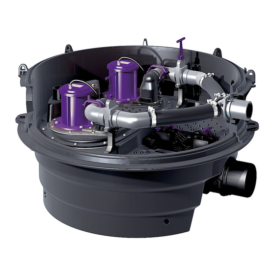
- Page 24 Optical probe for backwater flap (13) Motor for backwater flap* (14) Motor for redundant valve* (15) Comfort PLUS control unit (16) Control unit for Ecolift XL redundant valve* *) Option **) DN150 24 / 116 Backwater lifting station / Installation and operating instructions 010-694...
- Page 25 How the Ecolift XL works When installing the backflow loop, allow 15 cm accumulation height above the lowest relaxation point, and add 10 cm safety for the suction lifting effect. Normal installation depth Free-standing set-up Ecolift XL Public sewer chamber...
-
Page 26: Technical Data
Technical data Pumps Information / pump type 1400 1500 3000 4500 Weight 24 kg 24 kg 25 kg 26 kg Power P1 / P2 1.6 kW / 1.1 kW 1.4 kW / 1.1 kW 3.2 kW / 2.7 kW 4.5 kW / 3.7 kW Speed 1370 rpm 1415 rpm... -
Page 27: Installation
Initial commissioning (see "System commissioning", page 32). Fixing the tank Fix the Ecolift XL tank in exposed installation all around with conventional angle connectors 50 x 50 mm. These are each screwed into the side of the tank with 4 no. - Page 28 Installing and removing the pump(s) Installation Fix the wastewater pump(s) using the screws (1) (tighten- ing torque 7Nm). Install a welded PE pipe as the pressure pipe. Install an additional pressure release chamber for pump SPF 4500. Removal To make removal of the pump from the chamber easier, remove the plug (1) from the pump housing. Screw in the lifting eye/bolt (2) (M8 not included in the scope of supply).
- Page 29 Fix the optical probe on the backwater flap(s) Depending on the model type, there are either one or two optical probes for backwater detection included in the scope of delivery. These are fitted as follows: Cable marking Function none Backwater flap yellow Redundant valve Backwater flap probe...
- Page 30 Fitting the drive motor of the backwater flap (s) (option) One or two drive motors are included in the scope of deliv- ery, depending on the version. Cable marking Function grey Backwater flap black Redundant valve Fix the drive motor (2) on the backwater flap and optionally on the redundant valve as follows: If the position has not already been selected, move the locking lever (4) into the “CLOSED”...
- Page 31 Terminals (3) Cable colours Terminals Main control unit Connecting cable (2) Redundant control unit (5) w (do not connect White w (do not connect black Blue * Insulate or shorten any unused wire ends Connect the probe of the redundant valve (yellow cable marking) (4) to the FKA Comfort control unit (2) (connection with yellow marking).
-
Page 32: System Commissioning
System commissioning Always avoid the pumps running dry (air is drawn in) for longer periods (> 30 seconds). The pumps can become dam- aged. Do not activate pumps in manual operation if the system tank is not filled to at least minimum level. Open the shut-off valve The shut-off valve was pushed in for transport. -
Page 33: Operation
Operation Switching on the system All backflow preventers must be functional during operation. During operation, the shut-off valve must always be open and locked with a valve lock. Turn main switch (1) to I (ON) position. Following a successful system test, the system informa- tion appears on the display (2) and the green LED (3) lights up. - Page 34 Activating holiday mode Press button (3). Acknowledge the acoustic alarm signal emitted using the button (3). The backwater flap(s) is/are closed. The backwater lifting station pumps the wastewater that occurs into the wastewater sewer via the connected pipe. Switching off the system Turn main switch (1) to O (OFF) position.
-
Page 35: Maintenance
Maintenance Comply with EN 13564 during maintenance. The dismantling/installation of the pump is described under installation ("Installing and removing the pump(s)", page 28). Maintenance interval The system must be maintained regularly by a competent skilled person. The intervals must not be exceed: 1/2 year in commercial use 1 year in private households A maintenance protocol with details of all the work carried out and the main data must be prepared for all maintenance work. - Page 36 Under normal intended use conditions a voltage of 16V is sufficient until the next specified maintenance. The voltage is given in the control unit menu, under “Current measured values”. The seals of the lockable cover and the slide-in flap housing (towards the drain body) may only be greased with KESSEL high-performance grease (art. no. 681001).
- Page 37 Backflow preventer maintenance Close both shut-off valves. Vent the backflow preventer. If no flowing noises occur after venting, maintenance work must be carried out on the back- flow preventer. Carry out the maintenance of the backflow preventer as follows. Undo the hexagon screws on the flange. Open the one-handed closure.
- Page 38 Chère cliente, cher client, En qualité de producteur de pointe de produits novateurs dans le domaine de la technique d’assainissement, KESSEL pro- pose des réponses systématiques globales et un service orienté aux besoins de la clientèle. Nous misons simultanément sur les normes de qualité les plus élevées et une durabilité conséquente – non seulement lors de la fabrication de nos pro- duits, mais également pour leur utilisation à...
-
Page 39: Informations Spécifiques Aux Présentes Instructions
Informations spécifiques aux présentes instructions Les conventions de représentation suivantes facilitent l’orientation : Représentation Explication voir figure 1 Numéro de repère 5 de la figure ci-contre Action de la figure Vérifier si le mode manuel a été activé. Condition de réalisation de l’action Valider <OK>. -
Page 40: Sécurité
Déterminer la classe de charge requise et la statique suivant la situation environnementale et les conditions d'uti- lisation. Demander le plan d'armature correspondant auprès de la ligne d'assistance de KESSEL. AVIS Surface contaminée ! Le système et l’environnement peuvent être souillés par des germes. - Page 41 à risques s’y rapportant et d'attirer l’attention sur ces zones, de veiller à la mise en pratique de formations se rapportant aux consignes de sécurité, d’empêcher toute personne non autorisée de l’utiliser. Personne Activités autorisées sur les postes KESSEL Exploitant Contrôle visuel, remplacement de la batterie Technicien spécialisé...
- Page 42 Moteur du clapet antiretour* (14) Moteur de la redondance de fermeture* (15) Gestionnaire Comfort PLUS – unité de contrôle (16) Gestionnaire à redondance de fermeture Ecolift XL* *) option **) DN150 42 / 116 Poste de relevage à protection antiretour / 010-694...
- Page 43 Principe de fonctionnement - Ecolift XL Lors de l'installation de la boucle de refoulement, prévoir une hauteur supplémentaire de 15 cm au-dessus des eaux les plus hautes, et ajouter 10 cm de sécurité pour éviter un désiphonnage. Profondeur de pose normale Pose libre à...
-
Page 44: Caractéristiques Techniques
Caractéristiques techniques Pompes Indication / type de pompe 1400 1500 3000 4500 Poids 24 kg 24 kg 25 kg 26 kg Puissance P1 / P2 1,6 kW / 1,1 kW 1,4 kW / 1,1 kW 3,2 kW / 2,7 kW 4,5 kW / 3,7 kW Régime 1370 min... -
Page 45: Montage
Montage du gestionnaire et connexion des composants électriques (cf. "Montage du gestionnaire", page 48). Première mise en service (cf. "Mise en service du poste", page 50). Fixation de la cuve Fixer la cuve Ecolift XL destinée à une pose libre avec des connecteurs coudés traditionnels de 50 x 50 sur tout le pourtour. - Page 46 Montage - retrait de la(des) pompe(s) Montage Fixer la(les) pompe(s) d'assainissement à l’aide de vis (1) (couple de serrage 7 Nm). Exécuter la conduite de refoulement en tant que tuyau en polyéthylène soudé. Prévoir également un puits de décharge de pression pour la pompe SPF 4500.
- Page 47 Fixer la sonde optique au(x) clapet(s) antiretour Suivant le modèle respectif, le détail de livraison comprend une ou deux sondes optiques de détection de reflux. Le montage s'effectue comme suit : Marquage des câbles Fonction néant Clapet antiretour Jaune Redondance de fermeture Sonde clapet antiretour Fixer la sonde (1) au clapet antiretour (A) et en option (B), pour ce faire :...
- Page 48 Montage du moteur d’entraînement du(des) clapet(s) antiretour (option) Suivant le modèle respectif, un ou deux moteurs d’entraîne- ment sont inclus dans la livraison. Marquage des câbles Fonction Gris Clapet antiretour noir Redondance de fermeture Fixer le moteur d’entraînement (2) au clapet antiretour et en option à...
- Page 49 Bornes (3) Couleurs des câbles Bornes Gestionnaire principal Câble de raccordement (2) Gestionnaire à redondance (5) w (ne pas raccorder Blanc w (ne pas raccorder Noir Bleu * Isoler ou raccourcir si besoin les extrémités de fil non utilisées Raccorder la sonde optique de la redondance de fermeture (marquage jaune du câble) (4) au gestionnaire FKA Comfort (2) (raccord avec le marquage de couleur jaune).
-
Page 50: Mise En Service Du Poste
Mise en service du poste Éviter impérativement toute marche à sec des pompes (l'air est aspiré) pendant une longue durée (>30 secondes). Cela pourrait endommager les pompes. Ne jamais mettre les pompes en marche tant que la cuve n'est pas remplie jusqu'au niveau minimum. Ouverture du dispositif d'arrêt Le dispositif d’arrêt a été... -
Page 51: Fonctionnement
Acquitter l’alarme : appuyer 1 fois sur la touche (3) et la maintenir enfoncée pendant plus de 5 secondes. Si monté Acquitter l’alarme sur le gestionnaire à redondance de fermeture Ecolift XL : Maintenir la touche (3) enfoncée pendant 5 secondes. Fonctions de toutes les touches / affichages Diode d’état opérationnel Diode d’alarme... - Page 52 Activation du mode vacances Appuyer sur la touche (3). Acquitter le signal d'alarme qui retentit avec la touche (3). Le(s) clapet(s) antiretour est/sont fermé(s). Le poste de relevage à protection antiretour pompe les eaux usées produites dans la canalisation des eaux d’égout via la conduite raccordée.
-
Page 53: Maintenance
Maintenance Il convient d’observer la norme DIN EN 13564 lors des travaux de maintenance. Le (dé)montage de la pompe est décrit sous le montage ("Montage - retrait de la(des) pompe(s)", page 46). Intervalle de maintenance La maintenance du poste doit être réalisée à intervalles réguliers par une personne qualifiée. Respecter les intervalles sui- vants : tous les six mois dans le domaine industriel une fois par an dans le secteur privé... - Page 54 La tension est visible dans le menu du gestionnaire sous « valeurs de mesure actuelles ». Les joints du couvercle de verrouillage et de l’élément coulissant (en direction du corps de base) doivent exclusivement être enduits de graisse haute performance KESSEL (réf. 681001). Préparation de la maintenance Vérifier s’il y a un reflux (affichage sur le gestionnaire).
- Page 55 Maintenance du dispositif antiretour Fermer les deux dispositifs d'arrêt. Ouvrir le dispositif antiretour. Si, après cette étape, vous n’entendez aucun bruit d'écoulement, il est nécessaire de procé- der à la maintenance du dispositif antiretour. Procéder comme suit pour la maintenance du dispositif antiretour. Desserrer les vis six pans sur la bride.
- Page 56 Cara cliente, caro cliente, in qualità di produttore premium di prodotti innovativi per la tecnica di drenaggio, KESSEL offre soluzioni di sistema integrate e un servizio orientato al cliente. Puntiamo sui massimi standard qualitativi e ci impegniamo coerentemente per la sosteni- bilità...
-
Page 57: Indicazioni Sulle Presenti Istruzioni
Indicazioni sulle presenti istruzioni Le seguenti convenzioni illustrative semplificano l’orientamento: Simbolo Spiegazione vedere figura 1 Posizione numero 5 della figura accanto Passaggio procedurale nella figura Controllare se il funzionamento manuale è Presupposti per l’azione stato attivato. Premere OK. Passaggio procedurale L’impianto è... -
Page 58: Sicurezza
Determinare la classe di carico e la statica necessarie sulla base dell’ambiente circostante e delle condizioni d’uso. Richiedere il rispettivo piano di armatura al centralino KESSEL. AVVISO Superficie contaminata! L’impianto e l’ambiente circostante possono essere contaminati dai batteri. - Page 59 Persona Mansioni ammesse sugli impianti KESSEL Esercente Controllo visivo, sosti- tuzione della batteria Esperto (conosce e com- Svuotamento, puli- prende le istruzioni per l’uso)
- Page 60 Motore della clapet antiriflusso* (14) Motore della chiusura ridondante* (15) Centralina Comfort PLUS (16) Centralina della chiusura ridondante Ecolift XL* *) Opzionale **) DN150 60 / 116 Sistema di sollevamento contro il riflusso / 010-694 Istruzioni per l’installazione e l’uso...
- Page 61 Principio di funzionamento – Ecolift XL Al momento della progettazione della curva antiriflusso, prevedere un’altezza di accumulo di 15 cm sopra al punto di sca- rico più basso e una sicurezza supplementare di 10 cm per l’effetto di sifone. Profondità di installazione normale...
-
Page 62: Dati Tecnici
Dati tecnici Pompe Indicazione / tipo di pompa 1400 1500 3000 4500 Peso 24 kg 24 kg 25 kg 26 kg Potenza P1 / P2 1,6 kW / 1,1 kW 1,4 kW / 1,1 kW 3,2 kW / 2,7 kW 4,5 kW / 3,7 kW Numero di giri 1370 min... -
Page 63: Montaggio
Realizzazione del collegamento del condotto di mandata Il collegamento del condotto di mandata è realizzato in PE DN 80 (DA=90 mm) SDR 17. KESSEL raccomanda il collegamento di manicotti elettro-saldabili PE-HD disponibili in commercio. Collegamento del condotto di aerazione e sfiato AVVERTENZA Se il condotto di aerazione e sfiato non è... - Page 64 Montaggio-rimozione delle pompe Montaggio Fissare le pompe delle acque di scarico con le viti (1) (momento di serraggio 7 N·m). Realizzare il tubo di mandata quale tubo PE saldato. Con la pompa SPF 4500, posare inoltre un pozzetto di scarico della pressione. Rimozione Per una rimozione semplice della pompa dal pozzetto, togliere il tappo (1) dall’alloggiamento della pompa.
- Page 65 Fissaggio della sonda ottica sulle clapet antiriflusso La dotazione, a seconda della variante, comprende una o due sonde ottiche per l’identificazione del riflusso. Queste vengono montate come segue: Marcatura del cavo Funzione Nessuna Clapet antiriflusso Giallo Chiusura ridondante Sonda della clapet antiriflusso Fissare la sonda (1) alla clapet antiriflusso (A) e, in via opzionale, (B);...
- Page 66 Montaggio del motore di propulsione delle clapet antiriflusso (opzionale) La dotazione comprenderà uno o due motori di propulsione a seconda della versione. Marcatura del cavo Funzione Grigio Clapet antiriflusso Nero Chiusura ridondante Fissare il motore di propulsione (2) alla clapet antiriflusso e, in via opzionale, alla chiusura ridondante come segue: Qualora la posizione non sia già...
- Page 67 Morsetti (3) Colori del cavo Morsetti Centralina principale Cavo di collegamento (2) Centralina ridondante (5) w (non collegare Bianco w (non collegare Nero * Eventualmente isolare o accorciare le estremità dei fili non usati Collegare la sonda della chiusura ridondante (marcatura del cavo gialla) (4) alla centralina FKA Comfort (2) (collega- mento con marcatura cromatica gialla).
-
Page 68: Messa In Funzione Dell'impianto
Messa in funzione dell’impianto Impedire assolutamente il funzionamento a secco delle pompe (aspirazione di aria) per un periodo prolungato (>30 secondi). Le pompe potrebbero subire dei danni. Attivare le pompe nel funzionamento manuale se il serbatoio non è stato riempito almeno fino al livello minimo. Apertura della paletta di chiusura La paletta di chiusura è... -
Page 69: Funzionamento
Conferma dell’allarme: premere il tasto (3) 1 volta e tenerlo premuto >5 secondi. Se presente Confermare l’allarme sulla centralina della chiusura ridon- dante Ecolift XL: Tenere premuto per >5 secondi il tasto (3). Funzioni di tutti i tasti / Visualizzazioni LED condizione di prontezza per il funzionamento LED allarme Conferma dell’allarme acustico... - Page 70 Attivazione della modalità vacanze Premere il tasto (3). Confermare il segnale d’allarme acustico con il tasto (3). Le clapet antiriflusso verranno chiuse. Il sistema di sollevamento contro il riflusso pompa le eventuali acque di scarico nella rete fognaria tramite le tubazioni collegate.
-
Page 71: Manutenzione
Manutenzione Per la manutenzione è necessario osservare la norma DIN EN 13564. Il montaggio (smontaggio) della pompa è descritto alla voce Montaggio ("Montaggio-rimozione delle pompe", pagina 64). Intervallo di manutenzione L’impianto deve essere manutenuto regolarmente a cura di una persona esperta. Gli intervalli temporali non devono essere superiori a: Sei mesi per gli impianti in ambito commerciale Un anno per gli impianti in ambito privato... - Page 72 Rimontare gli elementi inseribili e le clapet. Accertare che il coperchio si trovi nella posizione “CHIUSA”. Ingrassare con il grasso ad alte prestazioni KESSEL anche la leva sul lato inferiore del coperchio e le relative superfici di contatto con la clapet. Montare il coperchio.
- Page 73 Manutenzione del blocco antiriflusso Chiudere entrambe le palette di chiusura. Sfiatare il blocco antiriflusso. Se, dopo lo sfiato, non si odono più rumori di flusso, il blocco antiriflusso deve essere manu- tenuto. Procedere come segue per la manutenzione del blocco antiriflusso. Allentare le viti a testa esagonale sulla flangia.
- Page 74 Beste klant, Als premium fabrikant van innovatieve producten voor de afwateringstechniek biedt KESSEL totale systeemoplossingen en klantgerichte service. Wij stellen hierbij maximale kwaliteitsnormen en zetten consequent in op duurzaamheid, niet alleen bij de productie van onze producten, maar ook met het oog op hun langdurige gebruik zetten wij ons in voor een permanente bescherming van u en uw eigendom.
-
Page 75: Informatie Over Deze Handleiding
Informatie over deze handleiding De volgende weergaveconventies maken de oriëntatie eenvoudiger: Afbeelding Uitleg zie afbeelding 1 Positienummer 5 van nevenstaande afbeelding Handeling op de afbeelding … Controleren of de handmatige bediening is Voorwaarde voor de handeling ingeschakeld. Op OK drukken. Werkstap De installatie is bedrijfsklaar. -
Page 76: Veiligheid
Statische belasting i.v.m. de verkeersveiligheid in acht nemen. Schachtinbouw voor belastingsklasse D vereist een lastverdeelplaat van gewapend beton (uitgezonderd bij een standaardopbouw van de weg). De vereiste belastingsklasse en statica conform de omgevings-/gebruiksomstandigheden bepalen. Passend wapeningsplan bij de KESSEL-hotline aanvragen. LET OP Verontreinigd oppervlak! Installatie en omgeving kunnen door kiemen zijn verontreinigd. - Page 77 De exploitant van de installatie is verplicht tot: het maken van een risicobeoordeling, het vaststellen en aantonen van gevarenzones, het uitvoeren van veiligheidsinstructies, het beveiligen tegen gebruik door onbevoegden. Persoon Vrijgegeven werkzaamheden bij KESSEL-installaties Exploitant Visuele controle, batterij vervangen Deskundige (kent en Leging, reiniging...
- Page 78 Optische sonde redundante afsluiter* (12) Optische sonde terugstuwklep (13) Motor terugstuwklep* (14) Motor redundante afsluiter* (15) Besturingskast Comfort PLUS - Control Unit (16) Besturingskast redundante afsluiter Ecolift XL* *) Optioneel **) DN150 78 / 116 Terugstuwpompinstallatie / Inbouw- en bedieningshandleiding 010-694...
- Page 79 Werkingsprincipe Ecolift XL Bij het plannen van de terugstuwlus moet rekening worden gehouden met 15 cm opstuwhoogte boven het laagste ont- spanningsniveau en bovendien 10 cm veiligheidsmarge voor het heveleffect. Normale inbouwdiepte Vrije opstelling Ecolift XL Put van het openbare riool Opstuwhoogte boven het ontspanningsniveau Hoogste punt van de terugstuwlus vanwege het heveleffect.
-
Page 80: Technische Gegevens
Technische gegevens Pompen Informatie / soort pomp 1400 1500 3000 4500 Gewicht 24 kg 24 kg 25 kg 26 kg Vermogen P1 / P2 1,6 kW / 1,1 kW 1,4 kW / 1,1 kW 3,2 kW / 2,7 kW 4,5 kW / 3,7 kW Toerental 1370 min 1415 min... -
Page 81: Monteren
KESSEL gebruiken. Persleiding aansluiten De aansluiting van de persleiding is uitgevoerd in PE DN 80 (DA = 90 mm), SDR 17. KESSEL beveelt het aansluiten van een gangbare elektrisch gelaste PE-HD-mof. Be - en ontluchtingsleiding aansluiten WAARSCHUWING... - Page 82 Pomp(en) monteren en verwijderen Monteren Afvalwaterpomp(en) met de schroeven (1) bevestigen (aanhaalmoment 7 Nm). De persleiding als gelaste PE-buis uitvoeren. Bij de pomp SPF 4500 ook een drukontlastingsschacht aanleggen. Verwijderen Om de pomp gemakkelijker uit de schacht te kunnen nemen, kunt u de dop (1) uit de pompbehuizing verwijderen. Oogbout (2) (M8, niet meegeleverd) indraaien.
- Page 83 Optische sonde bij terugstuwklep(pen) bevestigen Afhankelijk van de uitvoering zitten er één of twee optische sondes voor de herkenning van opstuwing in de leverings- omvang. Deze worden als volgt gemonteerd: Kabelmarkering Functie geen Terugstuwklep geel Redundante afsluiter Sonde terugstuwklep Sonde (1) bij de terugstuwklep (A) en optioneel (B) bevesti- gen, daarvoor: Sluitdop (2) verwijderen.
- Page 84 Aandrijfmotor terugstuwklep(pen) monteren (optioneel) In de leveringsomvang zitten afhankelijk van de uitvoering één of twee aandrijfmotoren. Kabelmarkering Functie grijs Terugstuwklep zwart Redundante afsluiter Aandrijfmotor (2) bij terugstuwklep, en optioneel bij de redundante afsluiter als volgt bevestigen: De sluithendel (4) in de positie DICHT zetten als hij daar nog niet in staat (zie afbeelding).
- Page 85 Klemmen (3) Kabelkleuren Klemmen Hoofdbesturingskast Aansluitkabel (2) Redundante besturingskast (5) w (niet aansluiten w (niet aansluiten zwart blauw * Eventuele ongebruikte aders isoleren of inkorten De optische sonde van de redundante afsluiter (gele kabelmarkering) (4) op de besturingskast FKA Comfort (2) aanslui- ten (aansluiting met gele markering).
-
Page 86: Inbedrijfstelling Van De Installatie
Inbedrijfstelling van de installatie Het voor langere tijd (> 30 seconde) droog laten lopen van de pompen (waarbij lucht wordt aangezogen) moet worden voorkomen. Dit kan de pompen beschadigen. De pompen mogen niet handmatig worden geactiveerd als het reservoir niet tot het minimumniveau is gevuld. Afsluiter openen De afsluiter wordt voor het transport gesloten. -
Page 87: Gebruik
Alarmtoon uitschakelen: toets (3) 1 x indrukken. Alarm resetten: toets (3) 1 x indrukken en 5 seconden ingedrukt houden. Voor zover aanwezig Op de besturingskast redundante afsluiter Ecolift XL het alarm resetten: Toets (3) 5 seconden lang ingedrukt houden. Functies van alle toetsen / indicaties... - Page 88 Vakantiemodus activeren Op toets (3) drukken. Het akoestische alarmsignaal met de toets (3) uitzetten. De terugstuwklep(pen) wordt/worden weer gesloten. De terugstuwpompinstallatie pompt aangevoerd water via de aangesloten leiding naar het riool. Installatie uitschakelen Hoofdschakelaar (1) in stand O (OFF) zetten. Er klinkt een alarmsignaal en de alarmled (4) knippert.
-
Page 89: Onderhoud
Onderhoud Tijdens onderhoud moet DIN EN 13564 worden gevolgd. De (de)montage van de pomp wordt beschreven onder Montage ("Pomp(en) monteren en verwijderen", pagina 82). Onderhoudsinterval De installatie moet regelmatig door een deskundige worden onderhouden. De intervallen mogen niet groter zijn dan: Een half jaar bij commercieel gebruik Eén jaar bij huishoudelijk gebruik Per onderhoud moet een onderhoudslogboek worden bijgehouden met alle uitgevoerde werkzaamheden en belangrijke... - Page 90 Zorgen dat het vergrendelbare deksel in de positie “DICHT” bevindt. Hendel aan de onderkant van het ver- grendelbare deksel en de contactoppervlakten daarvan met de klep ook met hoogwaardig KESSEL-vet insmeren. Vergrendelbaar deksel monteren. Als er sinds het laatste onderhoud terugstuw heeft plaats- gevonden, moet de pomp worden gedemonteerd en de be- en ontluchtingsopening worden schoongemaakt.
- Page 91 Onderhoud terugslagklep Beide afsluiters sluiten. Terugslagklep beluchten. Als na het beluchten geen stroomgeluiden klinken, moet de terugslagklep worden onderhou- den. Onderhoud aan de terugslagklep als volgt uitvoeren. Zeskantbouten van de flens losdraaien. Eenhandssluiting openen. Terugslagklep verwijderen. Verstoppingen en blokkerende voorwerpen verwijderen. Terugslagklep in een waterbad reinigen.
- Page 92 Szanowna Klientko, Szanowny Kliencie, jako producent najwyższej klasy innowacyjnych produktów z zakresu techniki odwadniania firma KESSEL oferuje komplek- sowe rozwiązania systemowe i serwis odpowiadający potrzebom klientów. Stawiamy sobie najwyższe standardy jakościowe i konsekwentnie stawiamy na trwałość – nie tylko podczas produkcji naszych urządzeń, lecz również w zakresie ich długo- trwałego użytkowania dbamy o to, by stale gwarantowane było bezpieczeństwo użytkownika i jego mienia.
-
Page 93: Wskazówki Dotyczące Niniejszej Instrukcji
Wskazówki dotyczące niniejszej instrukcji Poniższe formy oznaczeń ułatwiają orientację: Oznaczenie Objaśnienie Patrz rysunek 1 Numer pozycji 5 na rysunku obok Krok postępowania na rysunku Sprawdzić, czy aktywo- Warunek postępowania wana została obsługa ręczna. Nacisnąć przycisk OK. Krok postępowania Urządzenie jest gotowe do pracy. Wynik postępowania Odniesienie do rozdz. -
Page 94: Bezpieczeństwo
Przestrzegać statyki budowlanej dla bezpieczeństwa ruchu drogowego. Zabudowa w studzience dla klasy obciąże- nia D wymaga użycia płyty odciążającej z betonu zbrojonego (wyjątek: standardowa nawierzchnia drogi). Wymaganą klasę obciążenia i statykę należy wyznaczyć stosownie do otoczenia i warunków użytkowania. Plan zbrojenia można nabyć dzwoniąc do lokalnego oddziału firmy KESSEL. UWAGA Skażona powierzchnia! Urządzenie i otoczenie mogą... - Page 95 Użytkownik urządzenia jest zobowiązany do: sporządzenia oceny zagrożenia, wyznaczenia i oznakowania odpowiednich stref zagrożenia, przeprowadzenia instruktaży postępowania w razie niebezpieczeństwa, zabezpieczenia przed użyciem przez osoby nieupoważnione. Osoba Dozwolone czynności przy urządzeniach KESSEL Użytkownik Oględziny, wymiana baterii Osoba o odpowiednich Opróżnianie, czysz- kwalifikacjach (zna i rozu- czenie (wewnątrz),...
- Page 96 Sonda optyczna klapy zwrotnej (13) Silnik klapy zwrotnej* (14) Silnik zamknięcia rezerwowego* (15) Urządzenie sterujące Comfort PLUS - Control Unit (16) Urządzenie sterujące zamknię- cia rezerwowego Ecolift XL* *) opcja **) DN150 96 / 116 Przepompownia hybrydowa / Instrukcja zabudowy i obsługi 010-694...
- Page 97 Zasada działania – Ecolift XL Podczas projektowania pętli przeciwzalewowej należy zaplanować wysokość piętrzenia nad najniższym punktem spokoj- nym 15 cm i dodatkowo 10 cm na wypadek wystąpienia efektu lewara ssącego. Normalna głębokość zabudowy Ustawienie swobodne Ecolift XL Publiczna studzienka włazowa Wysokość...
-
Page 98: Dane Techniczne
Dane techniczne Pompy Dane / typ pompy 1400 1500 3000 4500 Ciężar 24 kg 24 kg 25 kg 26 kg Pobór mocy P1 / P2 1,6 kW / 1,1 kW 1,4 kW / 1,1 kW 3,2 kW / 2,7 kW 4,5 kW / 3,7 kW Prędkość... -
Page 99: Montaż
KESSEL. Utworzenie przyłącza przewodu tłocznego Przyłącze przewodu tłocznego należy wykonać w rurze PE DN 80 (DZ=90 mm) SDR 17. Firma KESSEL zaleca wykonanie przyłącza z użyciem dostępnych w sklepach muf elektrooporowych PE-HD. Podłączenie przewodu wentylacyjnego OSTRZEŻENIE Jeśli przewód wentylacyjny nie zostanie podłą-... - Page 100 Montaż i wyjęcie pompy Montaż Przykręcić pompę do ścieków śrubami (1) (moment dokręcający 7 Nm). Wykonać przewód tłoczny w formie spawanej rury PE. W przypadku pompy SPF 4500 dodatkowo doprowadzić ją do studzienki wyrównującej ciśnienie. Wyjęcie Aby pompę można było łatwiej wyciągnąć ze studzienki, należy wyciągnąć zaślepkę (1) z obudowy pompy. Wkręcić...
- Page 101 Montaż sondy optycznej na klapie zwrotnej Zależnie od wersji zakres dostawy obejmuje jedną lub dwie sondy optyczne do rozpoznawania przepływu zwrotnego. Montuje się je w następujący sposób: Oznaczenie kabla Funkcja Brak Klapa zwrotna Żółty kolor Zamknięcie rezerwowe Sonda klapy zwrotnej Przymocować...
- Page 102 Montaż silnika napędowego klapy zwrotnej (opcja) Zależnie od wersji zakres dostawy obejmuje jeden lub dwa silniki napędowe. Oznaczenie kabla Funkcja Szary kolor Klapa zwrotna Czarny kolor Zamknięcie rezerwowe Przymocować silnik napędowy (2) do klapy zwrotnej i opcjo- nalnie do zamknięcia rezerwowego w następujący sposób: Jeśli pozycja nie jest jeszcze wybrana, ustawić...
- Page 103 Zaciski (3) Kolor kabla Zaciski Główne urządzenie sterujące Kabel przyłączeniowy (2) Rezerwowe urządzenie sterujące (5) w (nie podłączać biały w (nie podłączać czarny niebieski * W razie potrzeby odizolować lub skrócić końce żył. Podłączyć sondę zamknięcia rezerwowego (żółte oznaczenie kabla) (4) do urządzenia sterującego FKA Comfort (2) (przyłącze oznaczone na żółto).
-
Page 104: Uruchomienie Urządzenia
Uruchomienie urządzenia Bezwzględnie unikać pracy pomp na sucho (zasysane jest powietrze) przez dłuższy czas (>30 s). Może to spowodować uszkodzenie pomp. Nie włączać pomp w trybie ręcznym, jeśli zbiornik urządzenia nie jest napełniony co najmniej do poziomu minimalnego. Otwarcie zasuwy odcinającej Zasuwa odcinająca została wsunięta na czas transportu. -
Page 105: Eksploatacja
Potwierdzenie alarmu: nacisnąć 1x przycisk (3) i przytrzy- mać wciśnięty przez >5 sekund. O ile obecne Potwierdzić alarm na urządzeniu sterującym zamknięcia rezerwowego Ecolift XL: Naciskać na przycisk (3) przez 5 sekund. Funkcje wszystkich przycisków / wskazań Dioda LED gotowości do pracy Dioda LED alarmu Kasowanie alarmu dźwiękowego... - Page 106 Aktywacja trybu wakacyjnego Nacisnąć przycisk (3). Potwierdzić sygnał alarmowy przyciskiem (3). Klapa zwrotna zostaje zamknięta. Przepompownia hybrydowa pompuje ścieki przez podłą- czoną rurę do kanału ściekowego. Wyłączenie urządzenia Ustawić wyłącznik główny (1) w pozycji O (OFF). Rozbrzmiewa sygnał alarmowy i miga dioda LED alarmu (4).
-
Page 107: Konserwacja
Konserwacja Podczas konserwacji przestrzegać normy PN-EN 13564. Demontaż i montaż pompy opisane są w rozdziale opisującym montaż ("Montaż i wyjęcie pompy", strona 100). Częstotliwość konserwacji Urządzenie wymaga regularnej konserwacji przez specjalistę. Odstępy czasu między konserwacjami nie mogą być większe niż: co pół... - Page 108 Wyczyścić wnętrze w obrębie klap. Nasmarować uszczelkę pokrywy zamykającej i powierzchnie styku mocowania klap ze zbiornikiem urządzenia smarem wysokowydajnym KESSEL (nr art. 681001). W razie potrzeby można również nasmarować powierzch- nie styku między dźwignią ryglującą i klap smarem wyso- kowydajnym KESSEL (nr art.
- Page 109 Konserwacja zaworu zwrotnego Zamknąć obydwie zasuwy odcinające. Napowietrzyć zawór zwrotny. Jeśli po napowietrzeniu nie słychać odgłosów przepływu, zawór zwrotny wymaga konser- wacji. Podczas konserwacji zaworu zwrotnego należy postępować w następujący sposób: Odkręcić śruby z łbem sześciokątnym na kołnierzu. Otworzyć jednoręczne zamknięcie. Zdjąć...
- Page 112 Registrieren Sie Ihr Produkt online, um von einer schnelleren Hilfe zu profitieren! http://www.kessel.de/service/produktregistrierung.html KESSEL AG, Bahnhofstr. 31, 85101 Lenting, Deutschland...
Need help?
Do you have a question about the Ecolift XL and is the answer not in the manual?
Questions and answers