Table of Contents
Advertisement
Quick Links
Operation
®
E-Flo
System
For dispensing and metering sealants, adhesives, and other medium to high viscosity
fluids. For professional use only.
Not approved for use in explosive atmospheres or hazardous (classified) locations.
See page 5 for system component information.
Important Safety Instructions
Read all warnings and instructions in this
manual and in all related manuals before
using the equipment. Save all
instructions.
iQ Dispense
333587B
EN
Advertisement
Table of Contents

Subscribe to Our Youtube Channel
Related Manuals for Graco E-Flo iQ


Summary of Contents for Graco E-Flo iQ
- Page 1 Operation ® E-Flo iQ Dispense System 333587B For dispensing and metering sealants, adhesives, and other medium to high viscosity fluids. For professional use only. Not approved for use in explosive atmospheres or hazardous (classified) locations. See page 5 for system component information. Important Safety Instructions Read all warnings and instructions in this manual and in all related manuals before...
-
Page 2: Table Of Contents
California Proposition 65 ....101 Graco Standard Warranty ....102 Pump Maintenance Screen 1. -
Page 3: Related Manuals
Related Manuals Related Manuals Related manuals in English: Manual Description 333585 iQ Dispense Valves, Instructions-Parts 333586 E-Flo iQ Dispense System, Installation-Parts 3A6321 ADM Token In-System Programming 312493 Light Tower Kit Instructions 3A1244 Graco Control Architecture Module 3A6482 APD20 Advanced Precision Driver... -
Page 4: Dispense System Configurator
Dispense System Configurator Dispense System Configurator The E-Flo iQ dispense system provides the flexibility to configure a complete system to meet your specific needs. This includes offering multiple combinations of the following components: • iQ Ram Supply Units • iQ Dispense Valves •... -
Page 5: Dispense System Components
Dispense System Components Dispense System Components NOTE: The Heated option for the E-Flo iQ system is for warm melt applications with a maximum temperature of 70° C (158° F). iQ Ram Supply Units Check the identification plate (ID) on the back of the ram post near the Power Junction Box (AJ) for the seven-digit part number of the iQ ram supply unit. -
Page 6: Iq Dispense Valves
Dispense System Components iQ Dispense Valves Check the identification plate on the valve for the ten-digit part number of the iQ dispense valve. Use the following matrix to define the construction of the valve, based on the ten digits. For example, Part No. V25AB060BA represents a valve (V) with 1/4 in. -
Page 7: Dispense System Pressure
Dispense System Pressure Dispense System Pressure Due to factors such as the dispense system design, the material being pumped, and the flow rate, the dynamic pressure will not reach the rated working (stall) pressure of the system. Pump Working (Stall) Pressure Max Dynamic (Run) Pressure Lower Size 4,000 29.0... -
Page 8: Warnings
Warnings Warnings The following warnings are for the setup, use, grounding, maintenance, and repair of this equipment. The exclamation point symbol alerts you to a general warning and the hazard symbols refer to procedure-specific risks. When these symbols appear in the body of this manual or on warning labels, refer back to these Warnings. Product-specific hazard symbols and warnings not covered in this section may appear throughout the body of this manual where applicable. - Page 9 Warnings WARNING MOVING PARTS HAZARD Moving parts can pinch, cut or amputate fingers and other body parts. • Keep clear of moving parts. • Do not operate equipment with protective guards or covers removed. • Equipment can start without warning. Before checking, moving, or servicing equipment, follow the Pressure Relief Procedure and disconnect all power sources.
- Page 10 Warnings WARNING SPLATTER HAZARD Hot or toxic fluid can cause serious injury if splashed in the eyes or on skin. During blow off of platen, splatter may occur. • Use minimum air pressure when removing platen from drum. TOXIC FLUID OR FUMES HAZARD Toxic fluids or fumes can cause serious injury or death if splashed in the eyes or on skin, inhaled, or swallowed.
-
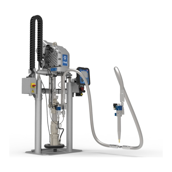
Page 11: Dispense System Component Identification
Dispense System Component Identification Dispense System Component Identification NOTE: Figure 1 shows a typical E-Flo iQ dispense system installation with an iQ ram supply unit, hoses, connectors, and an iQ dispense valve. Some installations may require only one hose depending on the needs of the system. -
Page 12: Tandem Ram
Dispense System Component Identification Tandem Ram NOTE: F . 2 shows a typical E-Flo iQ dispense system installation with a Tandem iQ ram supply unit, hoses, connectors, and an iQ dispense valve. Some installations may not require Supply Hose 2 (D) to iQ Dispense Valve (B) depending on the needs of the system. -
Page 13: Supply Unit Component Identification
Supply Unit Component Identification Supply Unit Component Identification iQ Ram Supply Unit D200 3 in. Dual Post Shown Ambient System Heated System . 3: iQ Ram Supply Unit Key: AA Ram Assembly AR Air Line (not supplied) AB Electric Driver AS Air Line Drain Valve (not supplied) AC Displacement Pump AT Air Filter (not supplied) -
Page 14: Power Disconnect
Supply Unit Component Identification Ambient System Power Disconnect Every E-Flo iQ Dispense System has a red and yellow Disconnect Switch which shuts off power to the entire system. The location of the switch is different for ambient and heated systems. See Figure 4. -
Page 15: Integrated Air Controls (Ag)
Supply Unit Component Identification Integrated Air Controls (AG) Integrated Air Line Accessories See Figure 3. The integrated air controls include: Air Line Drain Valve (AS): removes condensed • Main Air Slider Valve (BA): turns air on and off to • water from the air line. -
Page 16: Advanced Display Module (Adm)
Supply Unit Component Identification Advanced Display Module (ADM) Front and Rear Views . 6: ADM Component Identification Key: CA Startup/Shutdown CG Lock/Setup Starts up or shuts down the system. Toggles Toggles between Run screens and the iQ Menu. CH Directional Keypad between Active and Inactive system. -
Page 17: Adm Display Details
Five seconds after the E-Flo iQ blue token is inserted into the ADM, the Graco power up screen switches to The E-Flo iQ system includes a blue token that must be the E-Flo iQ power up screen. This screen remains on inserted into the ADM to initiate the E-Flo iQ software. - Page 18 ADM Display Details Screen Menu Press on any Run screen to switch to the iQ Menu The screen menu indicates the currently active screen, screens. If the system has a password lock, the which is highlighted. It also indicates the associated Password screen is displayed.
-
Page 19: Adm Led Status Descriptions
ADM Display Details ADM LED Status Descriptions Conditions Description System Status Green Solid Run Mode, System On Green Flashing Setup Mode, System On Yellow Solid Run Mode, System Off Yellow Flashing Setup Mode, System Off USB Status (CL) Green Flashing Data recording in progress Yellow Solid Downloading information to USB... -
Page 20: Adm Soft Keys
ADM Display Details ADM Soft Keys Icon Function Icon Function Pump Operation Icon Access the Advanced System Setup screens. Green: Start the Pump Access the Maintenance function. Inverted Green: Stop the Pump Access the Fieldbus Gateway Setup screens. Red with Border (enabled): Indicates that the pump cannot be started due to Access the Integration Feedback an alarm. - Page 21 ADM Display Details Icon Function Place all heat zones into setback and out of setback. Enter or exit manual pump movement mode. Move to the top. Move upward. Move downward. Move to the bottom. Reset Cycle Counter. Toggle between lifetime and resettable. Calibrate.
-
Page 22: Iq Menu
iQ Menu iQ Menu The iQ Menu screens provide access to settings that If you set a password, the menu will be displayed with help to ensure the proper operation and maintenance of red locks above the menu selections with parameters the system. -
Page 23: Setup
ADM, press the key from the Run screen to go to System field indicates that it is an E-Flo iQ system. the iQ Menu screens. Refer to iQ Menu on page 22. The Pump shows as Installed. The Serial Number... -
Page 24: Style Definitions
Setup When you select installed, the Serial Number will be 1. Press the soft key to enter editing mode. automatically populated to match the serial number printed on the driver ID tag on Pump 2. 2. Enter a Style identifier from 0-16. This is the designation the system uses for the type of If Pump 2 has a heat module installed, press the dispensing based on how you define the style here. - Page 25 Setup Name the Style Apply a Style Setting Globally You can also name the Style. While still in Style screen While still in Style screen 1, pressing the globalize 1, Press the soft key to advance to a keyboard soft key applies a style setting across all of the styles. A screen to create or change the name of the style based message will appear prior to completing the change.
-
Page 26: Pump Settings
Setup Pump Settings 1. In Remote mode, press the soft key to enter editing mode. Press the soft key at iQ Menu screen 1 to access the Pump setup screens. This function allows you to configure the operating settings for the pump and drum depending on the mode of operation. - Page 27 Setup Pump Screen 2 - Drum Settings 3. Select Alarm, Deviation, or None from the drop down menu for the Error Type. Use the ADM Directional Keypad (CH) to navigate to NOTE: The Over Pressure error will be triggered if the Pump screen 2.
-
Page 28: Heat Settings
Multi-Zone (AMZ) heat control. For example, heat zone triggered 3 seconds after reaching a critical level. number 4-7 corresponds to connector 4 and heat zone 7. For information about the AMZ, refer to the E-Flo iQ 6. Press the key to enable the Platen Valve Supply Systems, Installation-Parts manual. - Page 29 Setup Tandem Heat Setup Screen 1 4. Enter a temperature for the zone setback Read all of Heat Setup Screen 1 starting on page 28 temperature ( ) column. This is the setback that the zone goes to when the heat is in setback. The before reading this section.
- Page 30 Setup Heat Setup Screen 2 - Heat Soak In this example, the heat control box on Pump 1 (P1) is the one selected to heat the shared components Use the ADM Directional Keypad (CH) to navigate to running from the Tandem Block (R) to the Dispense Heat screen 2.
-
Page 31: Advanced Setup
Use the ADM directional keypad (BH) to change to iQ Menu screen 2. Press the soft key to access the Advanced Setup screens. This function allows you to configure the operating settings for E-Flo iQ system. Advanced Setup Screen 1 1. Press the soft key to enter editing mode. - Page 32 Setup 7. For the Password, enter any numbers from 0001 to 4. Select the Flow Rate from cc, gal(US), gal(UK), 9999. To remove the password, change the oz(US), oz(UK), liters, or cycles. password to 0000. This disables the password 5. Select the Drum Volume from cc, gal(US), gal(UK), function.
-
Page 33: Connect Light Tower Assembly
Additionally, this screen is used to update the system software using a USB drive with the latest software and a Graco black token. The latest software is provided on Help.graco.com. Refer to the ADM Token In-System Programming manual for a detailed description of this screen. -
Page 34: Startup
Startup Startup 3. Connect a hose to the 1 in. npt fitting on the top of Letters in parenthesis are used in this section for refer- the Check Valve Block (AE). Place the other end of ence to callouts in the Component Identification sec- the hose into a grounded waste container. -
Page 35: Load Material
Valve Port until you have completed loading material through the system. NOTE: For an E-Flo iQ system with a Platen Valve (AY) installed, you need to ensure that the Platen Valve setting is enabled in the Pump Settings on the ADM Platen Bleed before starting this procedure. - Page 36 Startup Load the Platen Valve and Recirculation 5. If a Platen Valve (AY) is installed on the system, Hose remove the cap from the Platen Valve Port located on the platen. NOTE: The following steps only apply to systems that 6.
-
Page 37: Tandem Priming When Changing Drums
Startup 2. Place a waste container below the Dispense Valve 5. Press the soft key to enter the pump priming (A). mode. 3. Ensure all fittings are secure from the Pump (AC) out to the Dispense Valve (A). 4. While still in pump priming mode and with the target pressure still set at 100 psi (0.7 MPa, 7 bar) and the target flow at 25 cc/min, press, the soft key to... -
Page 38: Operation
Operation Operation Ram Run Screen 10. Select to enter or exit priming mode. See Priming 1. Toggles between two modes of control: Local and Remote. See Control Modes on page 40. Mode on page 41. 2. Select to enter or exit the editing mode for the 11. -
Page 39: Tandem Run Screen
Operation Tandem Run Screen 11. Select to enter or exit priming mode. See Priming 1. Toggles between two modes of control: Local and Remote. See Control Modes on page 40. Mode on page 41. 2. Select to enter or exit the editing mode for the 12. - Page 40 Control Modes Red with No Border (not enabled): Indicates that the system is not enabled and the The E-Flo iQ system can be controlled locally or pump cannot be started. remotely. Pressing the soft key for this icon toggles back...
- Page 41 Operation NOTE: The depressurization process does not 4. A timer is shown to the left of the priming mode icon automatically stop. You need to manually stop and counts down when the priming starts. The depressurization as described below. default is 5 minutes but you can adjust the timer setting to between 1 and 9 minutes.
-
Page 42: Run Screen Editing Mode
Operation Heat Run Screen In the example above, the low level sensor is set to Deviation and the empty level sensor is set to Alarm to stop operation of the pump. When Heat is selected for a pump at the System Setup screen, a Heat Run screen is available. - Page 43 Operation The temperature units can be changed from °C to °F in the Advanced Settings screens. See Advanced Setup 2. When the icon is showing, you can put the Screen 2 on page 32. system into setback by pressing the soft key.
-
Page 44: Job Log
Operation Job Log Red text on the Job Log screen indicates that a job/style had a changeover during a dispense, meaning that the valve was open when the pump changed directions. Access the Job Log screens from the Run Home screen These are shown in red to indicate the changeover or iQ Menu screen 1 by pressing the soft key. -
Page 45: Events And Errors
Operation Events and Errors Events Log Screen Errors Log Screen This screen shows the Date, Time, Event Code, and This screen shows the Date, Time, Error Code, and Description of all events that have occurred on the Description of all errors that have occurred on the system. -
Page 46: Pressure Relief Procedure
Pressure . 7: Tandem Block Ball Valves 3. The current pump pressure and current dispense NOTE: To relieve pressure for the entire E-Flo iQ valve pressure show the progress of the depressurization on the Run screen. Dispense System, follow steps 1 through 12. To relieve pressure for the fluid side only, leaving air on to the ram 4. - Page 47 Pressure Relief Procedure NOTE: If using a Tandem system, perform steps 6 through 12 on both units. 6. If using an ambient system, turn the Disconnect Switch (AZ) OFF. If using a heated system, turn the Power Junction Box Switch (AK) and the Disconnect Switch (AZ) OFF.
-
Page 48: Shutdown The System
Maintenance Screen 1 on page 49 for information about manually moving the pump using the ADM. 5. Always flush the Pump before the fluid dries on the displacement rod. See the E-Flo iQ Supply System Operation manual for steps to flush the pump. 333587B... -
Page 49: Maintenance
Maintenance Maintenance Press the soft key at iQ Menu screen 2 to access the Maintenance screens. The Maintenance screens are the same for Tandem and Ram except Pump 2 will show in the Menu Bar. Use the ADM’s Directional Keypad (CH) to navigate to Pump 2. Pump Maintenance Screen 1 The Maintenance and Pump Position screen allows you to set maintenance parameters and view and change... -
Page 50: Pump Maintenance Screen 2
Maintenance When in editing mode with the Cycles Since Last Reset Press and hold the soft key to move the driver rod histogram showing, pressing the soft key on the down. The driver rod will move down as long as the soft key is held or until it reaches the bottom. -
Page 51: Diagnostics
Diagnostics Diagnostics Heat Diagnostics Screen Press the soft key at iQ Menu screen 1 to access the Diagnostics screens. These screens display key Use the ADM’s Directional Keypad (CH) to navigate to parameters that are useful in troubleshooting issues. the Heat Diagnostics Screen. This screen displays the current heat state, temperature, current, and duty cycle These Diagnostics screens are the same for Tandem at which the zone is currently running, along with the... -
Page 52: Pressure Diagnostics Screen
Diagnostics Pressure Diagnostics Screen The zone heat state is the circle with two numbers inside of it next to the zone heat symbol. There are four different color indicators for the heat zone. Use the ADM’s Directional Keypad (CH) to navigate to the Pressure Diagnostics Screen. -
Page 53: Troubleshooting
Troubleshooting Troubleshooting Press the soft key to advance to a keyboard screen that allows you to search for an error by error code. Type in the error code, then press the soft key to advance to advance to the QR Code screen. REMOTE SYSTEM ACTIVATION HAZARD See Style Definitions on page 24 for additional information about using the keyboard. - Page 54 QR code with your smart phone to be sent directly to online troubleshooting for the active error code. NOTE: For causes and solutions for each error code, refer to the Error Codes table on page 55. You can also call Graco Technical Assistance or navigate to: http://help.graco.com/en/e-flo-systems/e-flo-iq-system.h tml. 333587B...
-
Page 55: Error Codes
Troubleshooting Error Codes Error Error Location Type Error Name Description Cause Solution A1__ Alarm Low Current Heater current Fault heater Check heater resistance and resistance to H_Z_ is below the element ground. Replace faulty heater. minimum allowed value A2__ Advisory Low Current Heater current Fault heater... - Page 56 Troubleshooting Error Error Location Type Error Name Description Cause Solution A8__ Alarm No Current H_Z_ Power is not Power not getting to Check fuse on the AMZ that the error getting to heating element element is connected to. heating Check that electrical connector on the element heated hose is plugged into the AMZ.
- Page 57 Alarm Duplicate Module Multiple pumps Two or more pumps Update the pumps displaying the error to the using same have the same latest software available on help.graco.com. pump ID pump ID CCF_ Alarm FCM Comm. The FCM lost Restore communication.
- Page 58 Troubleshooting Error Error Location Type Error Name Description Cause Solution DD3_ Pump Alarm or Pump Diving P_ Pump diving Flow to pump inlet Check inlet valve is open or check inlet DD4_ Deviation detected restricted supply system for clogs. (user selectable) DKC_ Pump...
- Page 59 Troubleshooting Error Error Location Type Error Name Description Cause Solution Pump Record Automatic The system has The alarm in the No action necessary. Only Crossover to P_ success system requested a crossover to the crossover to the other the other other pump pump Pump...
- Page 60 Troubleshooting Error Error Location Type Error Name Description Cause Solution MAD_ Pump Advisory Maint. Due Pump Maintenance The number of Perform desired maintenance and reset the due for pump pump cycles since pump cycles in the setup screen. last reset has exceeded the maintenance limit MBD_...
- Page 61 Troubleshooting Error Error Location Type Error Name Description Cause Solution P6V_ Pump Alarm Valve Pressure Valve pressure The valve pressure Verify valve pressure transducer is installed Sensor P_ transducer not transducer is not and/or connected properly. Replace if connected. connected to the necessary.
- Page 62 Troubleshooting Error Error Location Type Error Name Description Cause Solution T4J_ Driver Alarm High Controls Temperature of The control board Ensure ambient temperature is below 120F Temperature P_ the control temperature inside (48C). board is too hot the driver is too high Enclosure fan not Verify fan in electrical enclosure is spinning.
- Page 63 Driver Alarm Software Software Hot board and cold Update the driver control board software to Mismatch P_ mismatch board have different the latest available on help.graco.com. detected in the software versions motor control board WNG0 Gateway Alarm Gateway Map Missing or Missing or invalid Install map in gateway.
-
Page 64: Usb Data
USB flash drive is inserted and data is Windows Explorer. downloaded or uploaded. 6. Open the GRACO folder. Event Log 7. Open the system folder. If downloading data from more than one system, there will be more than one The event log file name is 1-EVENT.CSV and is stored... -
Page 65: Job Log
NOTE: The automation log will only be recorded when there is a change in these parameters or in the automation status bits that are used by Graco to further The job log file name is 9-JOB.SCV and is stored in the diagnose the status of the system. -
Page 66: Create Custom Language Strings
• Define a custom string for each row in the second within the GRACO folder. Each folder is labeled with column. the corresponding serial number of the ADM (the NOTE: If the custom language file is used, you must serial number is on the back of the module). -
Page 67: Integration
NOTE: Connecting the ground on Connector 4, pin 3 is NOTE: See Connector Identification on page 68. required for the electric driver (AB) to receive valid signals. Connector Pin Use Graco Input / Output Description Communications and 24 Graco GCA CAN port. Connection to ADM, CGM, or another MCM... - Page 68 Connector 1 Connector 2 Connector 4 Connector 6 Connector 3 Connector 5 . 9: Electric Driver Connections Refer to the E-Flo iQ Supply System Installation-Parts Manual for additional information about Electric Driver Connections. See Related Manuals on page 3. 333587B...
-
Page 69: Job Cycle Timing Diagram
ADM is in Remote mode Job Cycle Timing Diagram Pre Job Cycle Pre-charge/De-charge Dispense 1 Dispense 2,3… Post Job Cycle Automation Inputs (E-Flo iQ Outputs) Heart Beat (1Hz) Automation Control Ready System Active +PLC Lockout/Control Active System Ready to Dispense Dispense In Process... -
Page 70: Discrete Timing Diagram
Discrete Timing Diagram Discrete Timing Diagram Pre Job Cycle Pre-charge/De-charge Dispense 1 Dispense 2,3… Post Job Cycle Automation Inputs (E-Flo iQ Outputs) System Ready to Dispense (C4-8) Automation Outputs (E-Flo iQ Inputs) System Enable/Remote Start Request (C4-5) Prechargring ‡Dispense Complete(C4-1) Notes: ‡... -
Page 71: Communications Gateway Module (Cgm)
The Communications Gateway Module (CGM) provides Unless stated otherwise, bytes are stored in each a control link between the E-Flo iQ system and a instance in little endian order (byte order within instance: selected fieldbus. This provides the means for report most significant to least significant). - Page 72 Integration Automation Inputs E-Flo iQ Advance Map 18A915 Automation INPUTS (signal from E-Flo iQ to PLC ) Instance ID Description Data Type Byte Heat Pump Heartbeat To PLC Boolean Automation Control Ready Boolean System Active Boolean ...
- Page 73 Integration Active Style Shot Size (xxx.xx cc) uint16 0-15 16-17 Actual Amount Dispensed uint32 0-31 18-21 (xxx.xx cc) Actual Shot Size uint32 0-31 22-25 (xxx.xx cc) Actual Style Fieldbus Pre-charge Request uint16 0-15 26-27 (xxx.x bars) Actual Style Fieldbus Flowrate Request ...
- Page 74 Integration E-Flo iQ Mode Active Boolean Resereved Bit 1 Boolean Resereved Bit 2 Boolean Resereved Bit 3 Boolean Resereved Bit 4 Boolean Resereved Bit 5 Boolean Resereved Bit 6 Boolean Resereved Bit 9 Boolean ...
- Page 75 Integration Heat Module Data Exchange Active Command uint16 0-15 60-61 † Heat Module Data Exchanged Active Command Value uint32 0-31 62-65 † Heat Heartbeat To PLC Boolean † System Heat Enabled Boolean † Heat PLC Lockout/Control Active Boolean † Heat is On Boolean †...
- Page 76 Integration Automation Outputs E-Flo iQ Advance Map 18A915 Automation OUTPUTS (signal from PLC to E-Flo iQ ) Instance ID Description Data Type Byte Heat SYS - Data Exchange Command uint16 0-15 System Enable/Remote Start Request Boolean System Disable Request ...
- Page 77 Integration Reserved Bit 2 Boolean † Reserved Bit 3 Boolean † Reserved Bit 4 Boolean † Reserved Bit 5 Boolean † Reserved Bit 6 Boolean † Reserved Bit 7 Boolean † Reserved Bit 8 Boolean † Reserved Bit 9 Boolean †...
- Page 78 Integration Pump Data Exchange E-Flo iQ Advance Map 18A915 Data Exchange (Pump) Command Value Name Units/Format (base 10 decimal) Pump Active Alarms Bitfield Pump Active Deviations Bitfield Pump Active Advisories Bitfield Driver Resettable Cycles Cycles Pump Resettable Cycles Cycles Platen Resettable Cycles...
- Page 79 Integration Enum Number: Drum Sizes 0: 20 Liters 1: 200 Liters Heat Idle Timeout xx hours Line Voltage, Leg #1 xxx Volts Line Voltage, Leg #2 xxx Volts Line Voltage, Leg #3 xxx Volts x000 AMZ Active Zone #x Alarms Bitfield x001 AMZ Active Zone #x Deviations...
- Page 80 Integration Pump Error Codes Pump Active Alarms Pump Active Deviation Alarm Deviation Alarm Name Deviation Name Number Code Number Code V1M_ Low Voltage P_ T2J_ Motor Temperatures Sensor P_ V4M_ High Voltage P_ T3J_ Temperature Cutback P_ T4M_ High Motor Temperature P_ WSC_ Encoder Calibration P_ T4J_...
- Page 81 Integration Pump Active Advisories Advisory Advisory Name Number Code MBD_ Maint. Due Driver P_ MAD_ Maint. Due Pump P_ MLC_ Rebuild Platen Seals P_ MG2_ Low Filter Pressure P_ MG3_ High Filter Pressure P_ MLD_ Maint. Due Platen Valve P_ MED_ Maint.
- Page 82 Integration Heat Error Codes AMZ Active Module Alarms AMZ Active Module Deviation Alarm Deviation Alarm Name Deviation Name Number Code Number Code V6H _ Wiring Error H_ V2H_ Low Voltage H_ V4H _ High Voltage H_ Reserved Reserved Reserved Reserved Reserved Reserved Reserved...
- Page 83 Integration AMZ Active Module Advisories I/O Daughter Board Active Module Alarms Advisory Alarm Alarm Name Advisory Name Number Code Number Code Heat Zone Offline Z1 H_ Reserved TA1_ Heat Zone Offline Z2 H_ Reserved TA2_ Heat Zone Offline Z3 H_ Reserved TA3_ Heat Zone Offline Z4 H_...
- Page 84 Integration I/O Daughter Board Active Module I/O Daughter Board Active Module Deviation Advisories Deviation Advisory Deviation Name Advisory Name Number Code Number Code Reserved Reserved Reserved Reserved Reserved Reserved Reserved Reserved Reserved Reserved Reserved Reserved Reserved Reserved Reserved Reserved Reserved Reserved Reserved Reserved...
- Page 85 Integration AMZ Active Zone #x Deviation AMZ Active Zone #x Alarms Deviation Alarm Deviation Name Alarm Name Number Code Number Code Reserved T4__ High Temperature H_Z_ Reserved T4__ High Temperature H_Z_ Reserved T1__ Low Temperature H_Z_ Reserved T8__ No Temperature Rise H_Z_ Reserved T4__ High Temperature H_Z_...
- Page 86 Integration AMZ Active Zone #x Advisories Advisory Code Advisory Name Number T3__ High Temperature H_Z_ T3__ High Temperature H_Z_ T2__ Low Temperature H_Z_ Reserved A3__ High Current H_Z_ A2__ Low Current H_Z_ Reserved Reserved Reserved Reserved Reserved Reserved Reserved Reserved Reserved Reserved Reserved...
-
Page 87: Prime Diagram
Integration Prime Diagram Prime Automation Inputs (E-Flo iQ Outputs) Automation Control Ready Heart Beat (1Hz) PLC Lockout Active Pump Trying to Move Prime Active (Timeout) Automation Outputs (E-Flo iQ Inputs) PLC Control Lockout Can all be Prime Pressure Target (integer) enabled at once. -
Page 88: System Enable - Remote Start Diagram
Integration System Enable - Remote Start Diagram System Enable-Remote Start Automation Inputs (E-Flo iQ Outputs) Heart Beat (1Hz) System is Active No Alarms Active Automation Outputs (E-Flo iQ Inputs) System Enable Request Note: Acknowledge - Clear Error Diagram Ack-Clear Error... -
Page 89: Manual Crossover Diagram
Integration Manual Crossover Diagram Manual Cross Over Automation Inputs (E-Flo iQ Outputs) Low Level Pump 1 (example) Heart Beat (1Hz) Tandem Active Pump (Pump 1 Active) (Pump 2 Active) Automation Outputs (E-Flo iQ Inputs) Cross Over Request Data Exchange Diagram... -
Page 90: Power Reset Diagram
Automation Outputs (E-Flo SP Inputs) System Enable / Remote Start Request PLC Control Lockout Heat CGM Timing Diagram Heat CGM Timing Automation Inputs (E-Flo iQ Outputs) Heart Beat (1Hz) System Heat Active Heat PLC Lockout/Active Automation Outputs (E-Flo iQ Inputs) -
Page 91: Heat Module Acknowledge-Clear Error Diagram
Integration Heat Module Acknowledge-Clear Error Diagram Heat Module Ack-Clear Error Automation Inputs (E-Flo iQ Outputs) Data Exchange - AMZ Module Alarms (integer/bitfield) Data Exchange - I/O Daughter Board Active Module Alarms (integer/bitfield) Heart Beat (1Hz) No Heat Module Alarms Active... -
Page 92: Heat Cgm Data Exchange Diagram
Integration Heat CGM Data Exchange Diagram Heat CGM Data Exchange Automation Inputs (E-Flo iQ Outputs) Heart Beat (1Hz) New Active Heat ModuleData Exchange Active Command Command Value Heat Module Data Exchange Active Command Value (5Hz) Automation Outputs (E-Flo iQ Inputs) -
Page 93: Connection Details
Integration Connection Details Module Status (MS) State Description Comments Fieldbus Not initialized No power or module in Connect cables to the fieldbus per fieldbus standards. “SETUP” or “NW_INIT” state PROFINET Green Normal Diagnostic event(s) operation present Flashing Initialized, Used by engineering tools Green diagnostic to identify node on... - Page 94 Integration EtherNet/IP DeviceNet Link 3 4 5 TI11814A TI11815A The EtherNet interface operates at 100Mbit, full duplex, as required by PROFINET. The EtherNet interface is Network Status (NS) auto-polarity sensing and auto-crossover capable. State Description Network Status (NS) Not online / No power State Description Green...
- Page 95 Integration 9 8 7 6 TI11816A Operation Mode (OP) State Description Not online / No power Green On-line, data exchange Flashing On-line, clear Green Flashing Red Parameterization error (1 flash) Flashing Red PROFIBUS Configuration error (2 flashes) Status Mode (ST) State Description No power or not initialized...
-
Page 96: Gateway Setup Screens
Integration Gateway Setup Screens PROFINET Screen 2 Press the soft key at the iQ Menu screen 2 to This screen allows you to set the Station Name, Install access the Fieldbus screens. The Fieldbus screens are Date, Location Tag, Function Tag, and Description. shown only if a Fieldbus CGM is installed. - Page 97 Integration EtherNet/IP PROFIBUS EtherNet Screen 1 PROFIBUS Screen 1 This screen allows you to set the IP Address, DHCP This screen allows you to set the Device Address, Install settings, subnet mask, gateway, and DNS information. Date, Location Tag, Function Tag, and Description. EtherNet Screen 2 PROFIBUS Screen 2 You can view the Hardware Revision, System Serial...
- Page 98 Integration DeviceNet At this screen, you can set the Device Address and Baud Rate and view the Hardware Revision, System Serial number, and data map identification information 333587B...
-
Page 99: Integration Feedback Screens
Discrete Integration Screen This screen shows the discrete integration robot signals that can be used when integrating the E-Flo iQ. The numbers to the right of each signal represent the connector and pin number on the E-Flo iQ driver. See Connector Identification on page 68. -
Page 100: Technical Specifications
Technical Specifications Technical Specifications E-Flo iQ Dispense Systems Metric Maximum fluid operating temperature 158°F 70°C Maximum working pressure 4000 psi 28 MPa, 276 bar Maximum driver cycle rate 25 cycles per minute Air inlet size (supply system) 3/4 npt(f) Ambient operating temperature range (supply 32-120°F... -
Page 101: Recycling And Disposal
End of Product Life At the end of a product’s useful life, recycle it in a responsible manner. For additional information refer to the E-Flo iQ Dispense System Installation-Parts manual. See Related Manuals on page 3. California Proposition 65 CALIFORNIA RESIDENTS WARNING: Cancer and reproductive harm –... -
Page 102: Graco Standard Warranty
With the exception of any special, extended, or limited warranty published by Graco, Graco will, for a period of twelve months from the date of sale, repair or replace any part of the equipment determined by Graco to be defective.
Need help?
Do you have a question about the E-Flo iQ and is the answer not in the manual?
Questions and answers