Table of Contents
Advertisement
Quick Links
Instructions - Parts
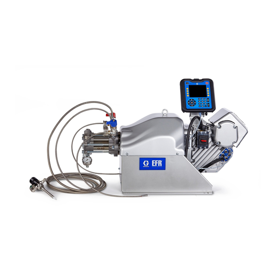
EFR
Electric Fixed-Ratio Proportioner
For use with two-component sealant and adhesive materials. For professional use only.
Not approved for use in explosive atmospheres or hazardous locations.
2000 psi (13.8 MPa, 138 bar) Maximum Fluid Inlet Pressure
3500 psi (24.1 MPa, 241 bar) Maximum Fluid Outlet Pressure
See page 3 for model information.
Important Safety Instructions
Read all warnings and instructions in this
manual and in related manuals before
using the equipment. Save these instruc-
tions.
3A6165A
EN
Advertisement
Table of Contents

Related Manuals for Graco EFR


Summary of Contents for Graco EFR
- Page 1 Instructions - Parts 3A6165A Electric Fixed-Ratio Proportioner For use with two-component sealant and adhesive materials. For professional use only. Not approved for use in explosive atmospheres or hazardous locations. 2000 psi (13.8 MPa, 138 bar) Maximum Fluid Inlet Pressure 3500 psi (24.1 MPa, 241 bar) Maximum Fluid Outlet Pressure See page 3 for model information.
-
Page 2: Table Of Contents
Maintenance ......21 Graco Information ......46 Preventative Maintenance Schedule . -
Page 3: Models
Models Models Use the following matrix to determine the 8-digit system part number. NOTE: To order replacement parts, see the Parts section on page 25. The digits in the matrix do not correspond to the Ref. Nos. in the Parts drawings and lists. Digit 4 Digit 5 Digit 6... -
Page 4: Warnings
Warnings Warnings The following warnings are for the setup, use, grounding, maintenance, and repair of this equipment. The exclama- tion point symbol alerts you to a general warning and the hazard symbols refer to procedure-specific risks. When these symbols appear in the body of this manual or on warning labels, refer back to these Warnings. Product-specific hazard symbols and warnings not covered in this section may appear throughout the body of this manual where applicable. - Page 5 Warnings WARNING SKIN INJECTION HAZARD High-pressure fluid from dispensing device, hose leaks, or ruptured components will pierce skin. This may look like just a cut, but it is a serious injury that can result in amputation. Get immediate surgical treatment. •...
- Page 6 Warnings WARNING MOVING PARTS HAZARD Moving parts can pinch, cut or amputate fingers and other body parts. • Keep clear of moving parts. • Do not operate equipment with protective guards or covers removed. • Equipment can start without warning. Before checking, moving, or servicing equipment, follow the Pressure Relief Procedure and disconnect all power sources.
-
Page 7: Keep Components A (Red) And B (Blue) Separate
Warnings Keep Components A (Red) and A (Red) and B (Blue) B (Blue) Separate Components NOTE: Material suppliers can vary in how they refer to plural component materials. For all machines: Cross-contamination can result in cured material in fluid lines which could cause serious injury or damage •... -
Page 8: Component Identification
Component Identification Component Identification . 1: Component Identification Key: A Pump B Pump Power Disconnect Switch Advanced Display Module (ADM) Pump Yoke Shroud Electric Driver Incoming Power Connection Pump Inlets Pump Outlets Driver Communication and I/O Connectors Lift Ring Pressure Relief Drain Tubes A-Side Outlet Drain Valve B-Side Outlet Drain Valve 3A6165A... -
Page 9: Typical Installation
Power Cord with User Supplied Dedicated Inlet Regulators Circuit Protection Dispense Valve* EFR Proportioner A Supply System* B Supply System* . 2: Typical Installation Required accessories not supplied with the proportioner. Optional accessories not supplied with the proportioner. -
Page 10: Advanced Display Module (Adm)
Component Identification Advanced Display Module (ADM) User Interface TI12362a1 . 3: ADM Component Identification - Front Buttons Callout Button Function Callout Button Function Soft Defined by application using ADM. System Enables/disables system. When Keys enable/ system is disabled, temperature disable control and dispense operation are Cancel Cancel a selection or number entry... - Page 11 Component Identification ti12363a1 . 4: ADM Component Identification - Rear Key: ADM Module Status LEDs (AN) Conditions AJ Flat Panel Mount AK Model Number AL USB Module Interface Module Status LED AM CAN Cable Connections Signal Description AN Module Status LEDs AP Accessory Cable Connections Green on System is powered up.
-
Page 12: Installation
Grounding provides an escape wire for the electric current. . 5: Power Cord EFR: grounded through the power cord (customer sup- 2. Remove the four screws to separate the junction plied). box cover (BA) and disconnect switch (C) from the junction box (BB) on the electrical driver. - Page 13 Installation NOTE: Inside the junction box, power wires are 4. Attach the ground wire to the ground terminal inside pre-installed to terminals 2T1 and 4T2 on the disconnect the junction box as shown in F . 8. block. Refer to F .
-
Page 14: Install Vented Oil Cap Before Using Equipment
Installation Install Vented Oil Cap Before Using Equipment The driver gear-box is shipped from the factory pre-filled with oil. The temporary unvented cap (PX) prevents oil leaks during shipment. This temporary cap must be replaced with the vented oil cap (PY), supplied with the equipment, before use. -
Page 15: Setup
Ensure the supply systems and, if applicable, the inlet regulators are off or set to zero pres- NOTE: Make sure the EFR is placed on a level surface. sure before connecting. See Dimensions on page 44 for space requirements. -
Page 16: Flushing
Setup Flushing Check Motor Position 1. Turn the power disconnect switch (C) to the OFF position. 2. Perform the Pressure Relief Procedure on page To avoid fire and explosion, always ground equipment and waste container. To avoid static sparking and 3. - Page 17 Setup Change Motor Position 5. Loosen the three nuts (D2) below the motor tie rods. There are specific motor positions for each mix ratio set- piston ting. To adjust the position of the electric driver: 1. Turn the power disconnect switch (C) to the OFF posi- tion.
-
Page 18: Operation
NOTE: The EFR is tested with oil at the factory. Flush eyes. To prevent cross-contamination of the equip- out the oil with a compatible solvent before dispensing. -
Page 19: Shutdown
5. Perform the Pressure Relief Procedure on page 1. Press the enable/disable key on the ADM disable the EFR, and verify it is inactive. 2. Relieve pressure and shut off the supply systems. See your appropriate supply system manual. -
Page 20: Adjust Material Inlet Pressure
Use only enough feed pressure to adequately sure gauge reads zero. feed the EFR pumps. The minimum feed pressure is 70 psi (0.48 MPa, 4.83 bar). 5. Place a grounded container at the outlet of the relief lines from the manifold assemblies and secure the 12. -
Page 21: Maintenance
If oil is low, valve manual open fill cap (FB) and add Graco Part No. 16W645 ISO 220 silicone-free synthetic EP gear oil. See F . 11. Clean dispense valve check... -
Page 22: Change The Oil
3. Reinstall the oil drain plug (FA). Torque to 18-23 ft-lb (25-30 N•m). To replace the battery: 4. Open the fill cap (FB) and add Graco Part 16W645 1. Perform the Shutdown procedure on page 19. ISO 220 silicone-free synthetic EP gear oil. Check 2. -
Page 23: Troubleshooting
3. Turn the power disconnect switch OFF. Try the recommended solutions in the order given for NOTE: For Online help, visit http://help.graco.com for each problem, to avoid unnecessary repairs. Also, causes and solutions to each error code. determine that all circuit breakers, switches, and con- trols are properly set and wiring is correct before assum- ing there is a problem. - Page 24 Troubleshooting Problem Cause Solution General Material imbalance Inadequate flow from pump; Increase fluid supply to proportion- ing pump: • Use minimum 3/4 in. (19 mm) ID supply hose, as short as practi- Clean inlet strainer screen Worn pump inlet valve ball/seat or gasket Erratic pump movement Pump cavitation...
-
Page 25: Parts
Parts Parts EFR Common System Parts 3A6165A... -
Page 26: Fluid Section
Parts Fluid Section A Side Pump B Side Pump 3A6165A... -
Page 27: Driver And Yoke Assembly
Parts Driver and Yoke Assembly Apply blue thread-locker. Torque to 0.8-1.13 N •m (7-10 in-lbs). Torque to 20-27 N •m (15-20 ft-lbs). Torque to 23-32 N •m (17-23 ft-lbs). Torque to 67-81 N •m (50-60 ft-lbs). Torque adapters to 122-135 N •m (90-100 ft-lbs). - Page 28 SCREW, flange head 110 191872 191929 FITTING, adapter 16V153 WASHER, retaining 113 295847 121116 FITTING, elbow, 3/4 npt 26B019 KIT, adm, efr 114 801787 113833 FITTING, tee 124* CABLE, can 115 100615 516308 BUSHING 125** 26B020 BRACKET, adm (includes 128,...
-
Page 29: Electrical Assembly
40A † danger 1 --- COVER, junction box --- - --- 240*† HARNESS, 4 113768 SCREW 113768 transformer, efr 1 --- KNOB, disconnect, panel Not shown 1 189930 228 LABEL, caution 189930 1 --- † Included in Transformer Kit 26A703 229†... -
Page 30: Accessories
The EFR Communication Gateway Module allows the 125296 3/4-NPT (m) x JIC-08 (m), Stainless Steel user to control an EFR through an external control 15M863 3/4-NPT (m) x JIC-12 (m), Stainless Steel device such as a PLC. See EFR Communication Gate- way Module manual for more information. -
Page 31: Advanced Display Module (Adm) Operation
Advanced Display Module (ADM) Operation Advanced Display Module (ADM) Operation When main power is turned on by turning the power dis- connect switch (C) to the ON position, the splash screen will be displayed until communication and initialization is complete. To begin using the ADM, the machine must be on and enabled. -
Page 32: Adm Screen Overview
ADM Screen Overview ADM Screen Overview Home Screen System Active Sequence Error and Events State Selected Display Status of Valve To select a sequence, use the navigation keys to high- light the active sequence bar. Then press the Enter but- to open a drop down menu where the desired sequence can be selected. - Page 33 ADM Screen Overview Along the right side of the home screen, there are icons De-Pressurize: When pressed, the de-pressurize icon that will allow the user to prime, park, de-pressurize, and purge the unit. will open the dispense valve, which will relieve pressure in the pump lines.
-
Page 34: Index Menu
NOTE: If the user selects seconds for the shot size, cal- ibration will no longer be an option for the selected shot size. NOTE: If the flow rate is set to zero, the EFR will wait for the specified amount of time before performing the next shot size. - Page 35 If selected, the EFR will wait for a trig- ger, such as a foot pedal, to be sensed before proceed-...
- Page 36 ADM Screen Overview Sequence Definition Screen 2 Setup Screen 1 This screen allows the user to copy, delete, and name This screen allows the user to change the dispense selected sequences. Use the arrow keys to select a mode, rate units, pressure units, pressure imbalance sequence from the list.
- Page 37 ADM Screen Overview Setup Screen 2 Advanced Screen 1 This screen allows the user to set a Gel Timer and Pres- This screen allows the user to change the language, sure Preset. date, and time shown on the ADM. The user can also set up a password and change the screen saver here.
- Page 38 ADM Screen Overview Maintenance Screen 1 Maintenance Screen 2 This screen keeps track of the cycles of the A and B This screen allows users to see the line voltage of the pump, both current and lifetime, as well as the number incoming AC power, the motor temperature, the per- of times the dispense valve has opened and closed.
- Page 39 ADM Screen Overview Shot Log Errors Screens This screen shows users a list of all completed shots. This screen shows users a list of errors that have Each shot entry includes a date and time stamp, the occurred in the system. Each error entry includes a sequence selected, the amount dispensed, and that description and error code along with a date and time start pressures of the A and B pumps.
- Page 40 ADM Screen Overview Integration Screen 1 USB Plug-In Screen This screen allows the user to see when the unit is This screen will appear when a USB device is plugged receiving inputs from a PLC, as well as when the unit is into the ADM.
- Page 41 ADM Screen Overview Remote Sequence Selection The active sequence can be changed using Connector #1 (AP) on the ADM. Selection bits are pulled high by default and must be dropped low to select the desired sequence. ADM Connector #1 (AP) NOTE: The view shown looking at the pins on the end of the cable.
-
Page 42: I/O Integration
Example: If the operator mode sequence step has a flow rate of 100cc/min. If analog flow rate signal of 5V is sent over, that will cor- respond to a 50 cc/min flow rate that the EFR will run at. 10V is 100cc/min, 7.5V is 75cc/min and 0V is 0cc/min. -
Page 43: Wiring Diagrams
Wiring Diagrams Wiring Diagrams NOTE: See the APD20 Advanced Precision Driver Instructions manual for driver internal wiring. Power Wiring Customer Ground Customer Power In Customer Ground Customer Power In 3A6165A... -
Page 44: Dimensions
Dimensions Dimensions A Machine Mounting Holes 21.5 in. (55 cm) For 3/8 in. (10mm) Mounting Fasteners B Machine Mounting Holes 21.1 in. (54 cm) C Total Machine Height 22 in. (56 cm) D Total Machine Length 50 in. (127cm) E Total Machine Width 22.5 in. -
Page 45: Technical Specifications
Technical Specifications Technical Specifications Metric Maximum fluid working pressure ‡ 3500 psi 24 MPa, 241 bar Maximum fluid temperature 120°F 50°C Fluid circulation ports 1/4 NPS(m) 200-240V, 1ph, 50/60 Hz Line voltage rating 400-480V, 1ph, 50/60 Hz Stainless steel, zinc-plated carbon steel, brass, tungsten Wetted parts carbide, chrome, fluoroelastomer, PTFE, ultra-high molec- ular weight polyethylene, silicon nitride... -
Page 46: Graco Standard Warranty
With the exception of any special, extended, or limited warranty published by Graco, Graco will, for a period of twelve months from the date of sale, repair or replace any part of the equipment determined by Graco to be defective.
Need help?
Do you have a question about the EFR and is the answer not in the manual?
Questions and answers