Table of Contents
Advertisement
Quick Links
Installation - Parts
®
E-Flo
System
For dispensing and metering sealants, adhesives, and other medium to high viscosity
fluids. For professional use only.
Not approved for use in explosive atmospheres or hazardous (classified) locations.
See page 4 for system component information.
Important Safety Instructions
Read all warnings and instructions in this
manual and in related manuals before
using the equipment. Save all
instructions.
iQ Dispense
333586D
EN
Advertisement
Table of Contents
Troubleshooting

Related Manuals for Graco E-Flo iQ Dispense System


Summary of Contents for Graco E-Flo iQ Dispense System
- Page 1 Installation - Parts ® E-Flo iQ Dispense System 333586D For dispensing and metering sealants, adhesives, and other medium to high viscosity fluids. For professional use only. Not approved for use in explosive atmospheres or hazardous (classified) locations. See page 4 for system component information. Important Safety Instructions Read all warnings and instructions in this manual and in related manuals before...
-
Page 2: Table Of Contents
Contents Shutdown and Care of the Pump ... . . 39 Related Manuals ......3 Change Drums . -
Page 3: Related Manuals
Graco Standard Warranty ....102 Supply System Communications Gateway Graco Information......102 313138... -
Page 4: Dispense System Configurator
Dispense System Configurator Dispense System Configurator The E-Flo iQ dispense system provides the flexibility to configure a complete system to meet your specific needs. This includes offering multiple combinations of the following components: • iQ Ram Supply Units • iQ Dispense Valves •... -
Page 5: Dispense System Components
Dispense System Components Dispense System Components NOTE: The Heated option for the E-Flo iQ system is for warm melt applications with a maximum temperature of 70° C (158° F). iQ Ram Supply Units Check the identification plate (ID) on the back of the ram post near the Power Junction Box (AJ) for the seven-digit part number of the iQ ram supply unit. -
Page 6: Iq Dispense Valves
Dispense System Components iQ Dispense Valves Check the identification plate on the valve for the ten-digit part number of the iQ dispense valve. Use the following matrix to define the construction of the valve, based on the ten digits. For example, Part No. V25AB060BA represents a valve (V) with 1/4”... -
Page 7: Dispense System Pressure
Dispense System Pressure Dispense System Pressure Due to factors such as the dispensing system design, the material being pumped, and the flow rate, the dynamic pressure will not reach the rated working (stall) pressure of the system. Pump Working (Stall) Pressure Max Dynamic (Run) Pressure Lower Size 4,000 29.0... -
Page 8: Warnings
Warnings Warnings The following warnings are for the setup, use, grounding, maintenance, and repair of this equipment. The exclamation point symbol alerts you to a general warning and the hazard symbols refer to procedure-specific risks. When these symbols appear in the body of this manual or on warning labels, refer back to these Warnings. Product-specific hazard symbols and warnings not covered in this section may appear throughout the body of this manual where applicable. - Page 9 Warnings WARNING MOVING PARTS HAZARD Moving parts can pinch, cut or amputate fingers and other body parts. • Keep clear of moving parts. • Do not operate equipment with protective guards or covers removed. • Equipment can start without warning. Before checking, moving, or servicing equipment, follow the Pressure Relief Procedure and disconnect all power sources.
- Page 10 Warnings WARNING EQUIPMENT MISUSE HAZARD Misuse can cause death or serious injury. • Do not operate the unit when fatigued or under the influence of drugs or alcohol. • Do not exceed the maximum working pressure or temperature rating of the lowest rated system component.
-
Page 11: Dispense System Component Identification
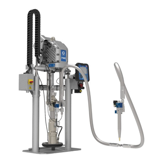
Dispense System Component Identification Single Ram NOTE: F . 1 shows a typical E-Flo iQ dispense system installation with a single iQ ram supply unit, hoses, connectors, and an iQ dispense valve. Some installations may require only one hose depending on the needs of the system. -
Page 12: Tandem Ram
Dispense System Component Identification Tandem Ram NOTE: F . 2 shows a typical E-Flo iQ dispense system installation with a tandem iQ ram supply unit, hoses, connectors, and an iQ dispense valve. Some Tandem E-Flo iQ Dispense Systems consist of two... -
Page 13: Supply Unit Component Identification
Supply Unit Component Identification Supply Unit Component Identification iQ Ram Supply Unit NOTICE Always lift the iQ Ram Supply Unit at the proper lift D200 3 in. Dual Post locations (see F . 3). Do not lift in any other way. Failure to lift at the proper lift locations can result in damage to the Supply System. -
Page 14: Power Disconnect
Supply Unit Component Identification Power Disconnect Ambient System Every E-Flo iQ Dispense System has a red and yellow Disconnect Switch which shuts off power to the entire system. The location of the switch is different for ambient and heated systems. See F . -
Page 15: Integrated Air Controls (Ag)
Supply Unit Component Identification Integrated Air Controls (AG) Air Line Accessories The integrated air controls include: See F . 3. • Main Air Slider Valve (BA): turns the air on and off • Air Line Drain Valve (AS) (not supplied): removes to the iQ Ram Supply Unit. -
Page 16: Advanced Display Module (Adm)
Supply Unit Component Identification Advanced Display Module (ADM) Front and Rear Views . 6: ADM Component Identification Key: CA Startup/Shutdown CG Lock/Setup Starts up or shuts down the system. Toggles Toggles between Run screens and the iQ Menu. between Active and Inactive system. CH Directional Keypad CB System Status Indicator LED Navigate within a screen or to a new screen. -
Page 17: Platen (Ad) Component Identification
Supply Unit Component Identification Platen (AD) Component Identification Ambient Heated Key: EA Plate EK O-ring Seal (not shown) EB Wiper EL Platen Valve Port EC Heater Cover EM Platen Valve Cap ED Cap Screws EF Bleed Stick EG Bleed Port EH Air Assist Body Check Valve EJ Wiper Plate (under wiper) 333586D... -
Page 18: Electric Driver Communication Connections
Supply Unit Component Identification Electric Driver Communication Connections Single Ram Port 1 Port 2 Port 4 Port 3 Connection Port 4 Connection Port 6 Port 3 Port 5 Pump Solenoid Dispense Valve Valve Power (M8 4 pin) Solenoid Junction Box (M8 4 pin) Port C3 Power... - Page 19 Supply Unit Component Identification Tandem Ram Port 1 Port 2 Port 4 Connection Port 3 Connection Port 4 Port 6 Port 3 Port 5 Pump Solenoid Tandem Tandem Valve Block Block Robot Power (M8 4 pin) Solenoid Controller Junction Box Splitter Splitter Port C3...
- Page 20 Supply Unit Component Identification Splitter from Tandem Block Cable from Tandem Block . 10: Communication Connections Key: Port 1 Connects to port C1 on the Power Junction Box. Port 2 Connects to port C2 on the Power Junction Box. Port 3 Connects to port C3 on the Power Junction Box (M12 5 pin), and to the platen valve solenoid (M8 4 pin).
- Page 21 Supply Unit Component Identification Low Level Sensor Kit, 25E447 NOTE: The Low Level Sensor Kit is an optional accessory for Single Ram Systems, and a required accessory for Tandem Ram Systems. To install the Low Level Sensor: 1. Turn the Disconnect Switch (AZ) OFF. 2.
-
Page 22: Power Junction Box And Heat Control Box Connections
Supply Unit Component Identification Power Junction Box and Heat Control Box Connections Single Ram Heated Ambient . 11 Key: C1 GCA CAN Port (to ADM) C5 Heated Hose/Accessory Connec- AK Power Junction Box Switch C2 GCA CAN Port (to CGM) tion AZ Disconnect Switch C3 Low and Empty Level Sensor Input... - Page 23 Supply Unit Component Identification Tandem Ram Heated Ambient . 12 iQ Ram Supply Unit 1 iQ Ram Supply Unit 2 Key: Key: C1 GCA CAN Port (to ADM splitter cable on Tandem Block C1 GCA CAN Port (to ADM splitter cable on Tandem Block (R) using the supplied CAN cable (124003)) (R) using the supplied CAN cable (124003)) C2 GCA CAN Port (to CGM)
-
Page 24: Installation
(A), see Dimensions on page 91. trician and comply with all local codes and regula- tions. NOTICE The E-Flo iQ Dispense System is shipped in five to six Always lift the iQ Ram Supply Unit at the proper lift containers: locations (see F . -
Page 25: Grounding
Installation Grounding Power Requirements Each iQ Ram Supply Unit requires a dedicated circuit protected with a circuit breaker. For Ambient Systems: The equipment must be grounded to reduce the risk of static sparking and electric shock. Electric or static Voltage Phase Current sparking can cause fumes to ignite or explode. - Page 26 Installation Heated Systems 1. Turn the Heat Control Box Disconnect Switch (AZ) OFF. Screws . 14: Remove the Power Junction Box Cover 4. Insert the power cord through the cord grip and into the Power Junction Box (AJ). Ground Lug Disconnect Switch Terminal Block .
-
Page 27: Attach Drum Stops
Installation Attach Drum Stops The iQ Ram Supply Units are shipped with drum stops in place to help position the drum on the Ram Assembly (AA). For replacement parts, order Kit 255477. The kit includes 2 each of capscrews, lock washers (not shown), and drum stops. -
Page 28: Install Vented Oil Cap Before Using Equipment
Installation Install Vented Oil Cap Before Using Equipment. The Driver gear-box is shipped from the factory pre-filled with oil. The temporary unvented cap prevents oil leaks during shipment. Replace this temporary cap with the vented oil cap supplied with the equipment before use. -
Page 29: Setup
NOTE: Do not connect any hoses if flushing the pump . 21 for the first time. See the E-Flo iQ Dispense System Operation manual for instructions on flushing the pump 4. If using a Single iQ Ram Supply System, connect and connecting hoses. - Page 30 Setup c. Connect Tandem Hose 1 (L) and Tandem Hose 7. Connect the Supply Hose 2 to Swivel Fitting (G) to the Swivel Fitting (H). 2 (M) from the supply system to the Tandem Block (R). See F . 23. d.
-
Page 31: Electrical Connections
Setup 10. If two hoses are used, connect Supply Hose 2 (D) to the Swivel Fitting (H) on the Dispense Valve (B) using the Supply Hose 2 to Swivel Fitting (G). If only Pressure one hose is used, connect Supply Hose 1 (C) to the Transducer Swivel Fitting (H) on the Dispense Valve (B) using Splitter... - Page 32 Setup NOTE: Make sure the pins on the solenoid valve cable b. Connect valve electrical connection to Supply are oriented as shown in F . 30 before the cable is Hose 1 square electrical connection if Supply plugged into the solenoid valve. Hose 2 is not used.
-
Page 33: Wet Cup
Setup Wet Cup Before starting, fill the Wet Cup (AN) 1/3 full with Graco Throat Seal Liquid (TSL) or a compatible solvent. Torque the Wet Cup The Wet Cup (AN) is torqued at the factory; however, throat packing seals on Severe Duty pumps may relax over time. -
Page 34: Hose Care Guidelines
Hose Care Guidelines Hose Care Guidelines Use hose support spring. Fluids subjected to heat in confined spaces can create a rapid rise in pressure due to the thermal expansion. Over-pressurization can result in equip- ment rupture and serious injury. • Open a valve to relieve the fluid expansion during Do not clamp, squeeze, or zip tie hose. -
Page 35: Check Resistance (Heated Systems)
Check Resistance (Heated Systems) Check Resistance (Heated Systems) Check Sensor Resistance Check Heater Resistance To reduce risk of injury or damage to equipment, To reduce risk of injury or damage to equipment, conduct these electrical checks with the Power conduct these electrical checks with the Power Junction Box Switch (AK) and the Disconnect Switch Junction Box Switch (AK) and the Disconnect Switch (AZ) OFF. - Page 36 Check Resistance (Heated Systems) Table 1: Sensors RTD Range RTD Pin Heater Element Heater Pin Port Zone Component (Ohms) Numbers Resistance (Ohms) Numbers Heated Hose G, K See hose manual See hose manual See accessory Heated Accessory 1 M, K See accessory manual manual Heated Hose...
-
Page 37: Pressure Relief Procedure
Pressure Relief Procedure Pressure Relief Procedure Follow the Pressure Relief Procedure whenever 2. At the ADM (AF) Run screen, press the soft you see this symbol. key for Valve Depressurization. Then press the soft key to open the iQ Dispense Valve (B) allowing the system to depressurize. - Page 38 Pressure Relief Procedure 6. If using an ambient system, turn the Disconnect Switch (AZ) OFF. If using a heated system, turn the Power Junction Box Switch (AK) and the Discon- nect Switch (AZ) OFF. 7. Open the Pump Bleed Valve (AM). Have a container ready to catch the drainage.
-
Page 39: Shutdown And Care Of The Pump
Shutdown and Care of the Pump Shutdown and Care of the Pump Change Drums NOTICE Keep hands away from the pump inlet to prevent To prevent damage to the pump from rust, never serious injury from moving parts. leave water or water-based fluid in a carbon steel pump overnight. - Page 40 Shutdown and Care of the Pump 2. Set the Ram Air Regulator (BB) to 0 psi. 3. Set the Ram Director Valve (BC) to UP. Ambient System 4. Slowly increase the pressure on the Ram Air Regulator until the Platen (AD) starts to raise, and immediately press and hold the Blowoff Button (BE) until the Platen is completely out of the drum.
-
Page 41: Maintenance
The oil level should be near the half- way point of the sight glass when the Driver (AB) is not running. If the oil is low, open the fill cap and add Graco Part No. 16W645 ISO 220 silicone-free synthetic EP NOTICE gear oil. -
Page 42: Platen Maintenance
Maintenance Platen Maintenance Remove and Reinstall Wipers Remove Platen Wipers NOTE: Five gallon Platens have a single Wiper that must be removed, and 55 gallon Platens have a top and bottom Wiper that must be removed. 1. Follow the steps to Change Drums on page 39. 1. -
Page 43: Recycling And Disposal
Maintenance Recycling and Disposal Reinstall Platen Wipers NOTE: Five gallon Platens have a single Wiper that must be reinstalled, and 55 gallon Platens have a top End of Product Life and bottom Wiper that must be reinstalled. At the end of the product’s useful life, dismantle and 1. -
Page 44: Troubleshooting
Troubleshooting Troubleshooting 2. Check all possible problems and causes before disassembling the Ram, Pump, or Platen. NOTE: Refer to Supply Unit Operation manual for descriptions of ADM diagnostic codes. NOTE: Refer to your Pump package manual for Pump troubleshooting. 1. Follow Pressure Relief Procedure, page 37, before checking or repairing the Ram, Pump, or Platen. -
Page 45: Heat Control Box Troubleshooting
Troubleshooting Heat Control Box Troubleshooting Problem Cause Solution System does not heat. Blown fuse. Replace fuse. Over-temperature switch tripped. Measure over-temperature switch resistance. It should read close to 0 ohms when at room temperature. If open, replace over-temperature switch. Cable to over-temperature switch is Check connection of cable to off or broken. -
Page 46: Repair
Repair Repair Disconnect Pump from Platen The Pump is mounted to the Platens by different mount- ing kits. See the Repair Kits on page 78. 55 Gallon Platen 1. Follow the Pressure Relief Procedure on page 37. 2. Turn off power to the ram: a. - Page 47 Repair 20, 30, and 60 Liter Platen 1. Follow the Pressure Relief Procedure on page 37. 2. Turn off power to the ram: a. If using an ambient Single Ram Supply System, turn the red Disconnect Switch (AZ) OFF. b. If using a heated Single Ram Supply System, turn the red Disconnect Switch (AZ) OFF.
-
Page 48: Connect Platen
Repair Connect Platen Remove Displacement Pump 55 Gallon Platen 1. Place o-ring (428) from mounting kit on the Platen (AD). If attached to plate, place Displacement Pump The procedure for removing the Displacement Pump (AC) onto Platen (AD). See F . - Page 49 Repair 5. Raise the Driver (AB): 7. Use two people to lift out the Displacement Pump (AC). a. Loosen nut (105a) under Ram bar and thread it down the threaded rod (106) to the lift ring adapter (107) holding the Driver (AB). Use wrench on nut (105) on top of Ram bar to raise Driver (AB).
-
Page 50: Install Displacement Pump
Repair Remove Driver 4. See Disconnect Pump from Platen on page 46 to disconnect the Platen (AD) from the Displacement Pump (AC). 5. Open the Main Air Slider Valve (BA). 6. Raise the Ram Assembly (AA) to lift the Driver (AB) To avoid serious injury when installing and removing away from the Displacement Pump (AC). - Page 51 Repair c. Loosen the cord grip (CG). 5. Disconnect Driver (AB): d. Remove wires from Driver housing by pulling a. D200 3 in. and D200s 6.5 in. ram supply units: them through the cord grip (CG). Attach a secure hoist to the driver lift ring. Loosen nut (125) below crossbar.
-
Page 52: Install Driver
Repair Install Driver 2. Connect power to the Driver (AB). Follow a-e of step 4 on page 50 in reverse. 3. If using an ambient system, turn the Disconnect Switch (AZ) ON. If using a heated system, turn the Power Junction Box Switch (AK) and the To avoid serious injury when installing and removing Disconnect Switch (AZ) ON. -
Page 53: Ram Supply Unit Repair
Repair Ram Supply Unit Repair 8. Remove guide sleeve (135) by sliding it off of rod (132). Four 1/4 in -20 holes are provided to ease removal of the guide sleeve. 9. Inspect parts for wear or damage. To reduce the risk of serious injury whenever you are instructed to relieve pressure always follow the Pressure Relief Procedure on page 37. - Page 54 Repair c. If using an ambient Tandem Ram Supply Assemble Ram Piston System, turn the red Disconnect Switch (AZ) 1. Install new o-rings (139, 137) on piston rod (132) OFF on the Ram Supply Unit that requires and piston (141). Lubricate the piston (141) and repair only.
- Page 55 Repair NOTE: Do not reinstall end cap assembly if the ram Disassemble Ram Piston piston (247) needs to be removed from the piston rod. 1. Complete steps 1-4 from Disassemble Piston Rod See the next page for ram piston repair instructions. Seal and Bearing to remove the end cap from the piston rod.
-
Page 56: Replace Heat Control Box Electrical Component(S)
Repair Replace Heat Control Box Electrical Component(s) 1. Turn the Heat Control Box Disconnect Switch (AZ) OFF. 2. Remove the door (350) on the Heat Control Box (AX). DANGER SEVERE ELECTRIC SHOCK HAZARD 3. Use a non-conductive fuse puller tool to remove the This equipment can be powered by more than 240 V. - Page 57 Repair Replace Advanced Display Module (ADM) b. Disconnect the cables from the AMZ on the inside of the Heat Control Box (AX). NOTICE c. Remove the four screws (333) used to mount The ADM stores useful lifetime and diagnostic data the AMZ to the back of the Heat Control Box that will be lost when it is replaced.
-
Page 58: Replace Fuses In Harness (25R652)
Repair Replace Fuses in Harness (25R652) The harness comes with fuses installed. Follow these steps to replace a fuse. 1. Turn the Heat Control Box Disconnect Switch (AZ) OFF. 2. Remove the Heat Control Box door (350). 3. Unscrew the spring-loaded fuse holder to open it. The fuse can be easily removed by hand. -
Page 59: Parts
Parts Parts D200s 6.5 in. Ram Supply Units Model EZC2661 Shown NOTE: If using a tandem system, the ADM is only included with the iQ Ram Supply Unit 1 (A). Detail A 102, 103, 107,108 Detail B 107,108 107,108 333586D... - Page 60 Parts D200s 6.5 in. Ram Supply Units, EZC2661 Ref. Part Description Qty. Ref. Part Description Qty. 15J074 LABEL, safety, crush & pinch 102040 C32401 110755 WASHER, plain 133* C03043 RING, snap 117017 WASHER 134* C31001 WIPER, rod 15V954 LABEL, valve, shutoff, air con- 617414 SLEEVE, guide trol...
-
Page 61: D200 3 In. Ram Supply Units
Parts D200 3 in. Ram Supply Units Model EZC2561 Shown NOTE: If using a tandem system, the ADM is only included with the iQ Ram Supply Unit 1 (A). Detail A 102, 107, 103,113 107,108 107,108 205, Detail B 107,108 201, 213, 107,108... - Page 62 Parts D200 3 in. Ram Supply Units, EZC2561 Ref. Part Description Qty. Ref. Part Description Qty. 167646 BEAM, tie 102040 NUT RAM, weldment, 3” 110755 WASHER, plain 255296 BRACKET, mounted, painted 117017 WASHER 128863 FITTING, elbow 15V954 LABEL, valve, shutoff, air control BRACKET, mounting, btm LABEL, cross bar BRACKET, mounting, acc.
-
Page 63: D60 3 In. Ram Supply Units
Parts D60 3 in. Ram Supply Units Model EZC2424 Shown NOTE: If using a tandem system, the ADM is only included with the iQ Ram Supply Unit 1 (A). Detail A 254,125 102, 107,108 103,113 107,108 205, 107,108 Detail B 201,107 107,108 333586D... - Page 64 Parts D60 3 in. Ram Supply Units, EZC2424 Ref. Part Description Qty. Ref. Part Description Qty. SEALANT, thread, med strength 102040 NUT 238* BEARING, ram end cap 110755 WASHER, plain 239* 156401 PACKING, o-ring 117017 WASHER 240* 156698 PACKING, o-ring 15V954 LABEL, valve, shutoff, air control 241* 15F453 RETAINER, retaining ring...
-
Page 65: D200, D200S Pump Mounts For 55 Gallon (200 Liter) Platen
Parts D200, D200s Pump Mounts for 55 Gallon (200 Liter) Platen Note: See page 59 for kit configuration table. 303, 305 302, 304 TI10771A Ref. Part Description 15M531 ROD, platen 101015 WASHER, lock C19187 101533 WASHER, spring lock 101535 ROD, threaded 15J991 ADAPTER, lift, ring 15J993... -
Page 66: D60 Pump Mount For 5 Gallon (20 Liter) Platen
Parts D60 Pump Mount for 5 Gallon (20 Liter) Platen Ref. Part Description Qty. 306 --- BRACKET, shelf, NXT3400 and NXT6500 307 101533 WASHER, spring lock 308 101535 309 100133 WASHER, lock 310 C38372 SCREW 333586D... -
Page 67: D200S Pump Mounts For 16 Gallon (60 Liter) Platens
Parts D200s Pump Mounts for 16 Gallon (60 Liter) Platens Ref. Part Description Qty. 361 15M298 ROD, tie bar, shelf 362 101533 WASHER, lock 363 101535 NUT, hex 364 --- BRACKET, shelf 365 100133 WASHER, lock 366 --- SCREW, cap, hex hd 367 --- ROD, threaded 368 ---... -
Page 68: Power Junction Box
Parts Power Junction Box Ambient Power Junction Box 205, 217 Ref. Part Description Qty. Ref. Part Description Qty. 123967 KNOB, disconnect, operator 108050 WASHER, lock, spring 123970 SWITCH, disconnect, 40A 121518 SCREW 121171 GRIP, cord BRACKET, cable track mount, 196548 LABEL, caution painted 324* ---... - Page 69 Parts Heated Power Junction Box See Detail A See Detail B See Detail C Detail C Detail B Detail A Ref. Part Description Qty. Ref. Part Description Qty. 321† 123970 SWITCH, disconnect, 40A 205* 108050 WASHER, lock, spring 196548 LABEL, caution 217* 121518 SCREW...
-
Page 70: Heat Control Box
Parts Heat Control Box 336, Ref. Part Description Qty. Ref. Part Description Qty. HARNESS, ground, heat ENCLOSURE, electrical, heat, 121000 CABLE, can, female/female 0.5m painted HARNESS, power, incoming 25R533 MODULE, gca 441† 111307 WASHER, lock, external 116595 SCREW 348† 16T440 121171 GRIP, cord LABEL, multiple, control, heat... -
Page 71: 55 Gallon Platen
Parts 55 Gallon Platen 200 Liter (55 Gallon) Platen, 255319 and 255320 *428 *426 *427 ti20583a 200 Liter (55 Gallon) Platen Parts Ref. Part Description Qty. 257697 HANDLE, bleed assy 255652 SEAL, wiper, drum, 55 gal., neo- prene; for 255664 only. 255653 SEAL, wiper, drum, 55 gal., EPDM;... -
Page 72: 20 Liter (5 Gallon) Platens
Parts 20 Liter (5 Gallon) Platens Ambient Heated 25R536 and 25R537 25R534 and 25R535 . 59: Single and Double Wiper Assemblies 333586D... - Page 73 Parts 20 Liter (5 Gallon) Platen Parts, Heated 20 Liter (5 Gallon) Platen Parts, Ambient (25R534 and 25R535) (25R536 and 25R537) Ref. Part Description Qty. Ref. Part Description Qty. BASE, platen, heated, recharge BASE, platen, heated, recharge 121829 O-RING, packing 121829 O-RING, packing PLATE, btm, 20 30L platen, PLATE, btm, 20 30L platen,...
-
Page 74: 60 Liter (16 Gallon) Platens
Parts 60 Liter (16 Gallon) Platens Ambient Heated (26B211) (26B210) . 60: Single and Double Wiper Assemblies 333586D... - Page 75 Parts 60 Liter (16 Gallon) Platen Parts, Heated 60 Liter (16 Gallon) Platen Parts, Ambient (26B210) (26B211) Ref. Part Description Qty. Ref. Part Description Qty. 18B822 BASE, platen, heated, recharge 18B822 BASE, platen, heated, recharge 121829 O-RING, packing 121829 O-RING, packing 256717 PLATE, bottom, platen 256717...
-
Page 76: Tandem Block, 25R848, 25R849
Parts Tandem Block, 25R848, 25R849 487, 488 Ref. Part Description Qty. Ref. Part Description Qty. 489* 124003 CABLE, can BLOCK, 3 way, S, 1” NPT 490* 124654 CONNECTOR, splitter C38302 FITTING, nipple 491* 25R439 KIT, low level sensor 473* SEALANT, pipe, SST 492* 121266 VALVE, shuttle 5/32 521477 VALVE, ball, 1”... -
Page 77: Kits And Accessories
Kits and Accessories Kits and Accessories Accessories are available from Graco. Make certain all accessories are adequately sized and pressure-rated to meet the system’s requirements. System Kits and Accessories Light Tower Kit, 255467 For D200s, D200, and D60 single supply systems. -
Page 78: Drum Kits And Accessories
Kits and Accessories Tandem Block Stand, 26B177 To install the Tandem Block Stand: For use with tandem systems only. 1. Use the holes in the Tandem Block Stand support (551) as a guide and drill holes for 1/2 in. (13 mm) anchors. -
Page 79: I/O Cable, 122029
Kits and Accessories I/O Cable, 122029 See the E-Flo iQ Supply System Operation manual for setup and pin out information. Part Description Length 15.0 m 128441 CABLE, GCA, M12-8p Platen/Pump Heat Harness Part Description Length 3.0 m 25R662 HARNESS, heat, platen/pump 3.7 m 25R663 HARNESS, heat, platen/pump... -
Page 80: Cable Kits
Kits and Accessories Cable Kits Tandem Fitting Kits Transducer Hose Connections Working Tandem Tandem Solenoid Hose Part Number Pressure Hose 1 Hose 2 Part Cable Cable Transducer 25R891 4500 psi (31 Number Length Length Transducer Adapter MPa, 310 bar) 25R342 33 ft (10 m) NA 15M669 15N034 25R892... -
Page 81: Check-Mate 200 Cs Pump Heater Kit, 25R450
Kits and Accessories Check-Mate 200 CS Pump Heater Kit, 25R450 503, 504, 502, See Detail A Detail A 512, 513 . 61: Check-Mate 200 CS Pump Heater Kit, 25R450 Ref. Part Description Qty. 116343 SCREW 121980 HEATER, pump, 725 watt 111307 WASHER 18B862... -
Page 82: Platen Heater Kit, 25R451
Kits and Accessories Platen Heater Kit, 25R451 Detail B 530, 531 Detail D Detail A 533, 534 Detail C . 62: Platen Heater Kit, 25R451 HARNESS, ground, 14awg, Ref. Part Description Qty. 18” long HARNESS, heat, wiper, 55 25R666 WASHER gallon CONDUCTOR, block, heater 116343... -
Page 83: Communication Gateway Module (Cgm) Kits
Kits and Accessories Communication Gateway Module (CGM) Kits Installing a CGM Kit All electrical wiring must be done by a qualified elec- trician and comply with all local codes and regulations 1. Follow the Pressure Relief Procedure on page 37. 2. - Page 84 . 66: Power Junction Box Port Locations c. Connect the other end of the 0.4m CAN cable NOTE: Longer CAN cables, if required, are available (121266) to the ADM splitter (124654). from Graco. See CAN Cables on page 78. 333586D...
- Page 85 . 67: CGM Fieldbus Connection 13. Connect the other end of the cable to the fieldbus device. 14. Refer to the Graco Control Architecture Module Pro- gramming manual for step-by-step instructions on how to update the software version of GCA mod- ules.
-
Page 86: Platen Valve Kit, 25R452
Kits and Accessories Platen Valve Kit, 25R452 . 68: Platen Valve Kit, 25R452 2. Disconnect the pressure transducer from port 5 on Ref. Part Description Qty. the Electric Driver (AB). VALVE, 25, npt/b, 000, V25AB000BA adj/sol, amb 3. Remove the pressure transducer fitting (TF) and the 100721 PLUG, pipe fitting it is attached to from the Fluid Check Valve... - Page 87 Kits and Accessories NOTE: Do not install the recirculation hose (607) onto 12. Remove the 1/4 NPT plug from the Integrated Air the platen valve fitting (603) until material has been Controls (AG). See Integrated Air Controls (AG) loaded into the platen valve (601). See the E-Flo iQ on page 15.
-
Page 88: Platen Valve Kit, 25R453
Kits and Accessories Platen Valve Kit, 25R453 . 72: Platen Valve Kit, 25R453 Ref. Part Description Qty. 710 17K616 FITTING, nipple VALVE, 25, npt/b, 000, 711 123140 FITTING, cap 701 V25AB000BA adj/sol, amb 712 --- SEALANT, pipe, sst 702 100721 PLUG, pipe 713 16D269 HOSE, assy... - Page 89 Kits and Accessories 12. The harness (714) has an M8 connector and an To install the Platen Valve Kit on a 55 gallon system: M12 connector. Connect the M12 connector that was originally connected to port 3 on the Electric Driver (AB) to the M12 connector on the harness (714).
- Page 90 Kits and Accessories 15. Connect the nylon tube (715) to the elbow fitting (716) and the platen valve (701). . 74 333586D...
-
Page 91: Dimensions
Dimensions Dimensions D200 3 in. D200s 6 in. Ram Supply System Ram Supply System D60 3 in. Ram Supply System 333586D... -
Page 92: Dimensions
Dimensions Dimensions Ram Size in. (mm) D200 D200s Total Height (A) 70 (1778) 88 (2235) 96 (2438) Ram Height (B) 57 (1448) 70 (1778) 69 (1753) Extended Ram 89 (2261) 118 (2997) 125 (3175) Height (C) Base Depth (D) 20 (508) 25 (635) 25 (635) Machine Width (E) -
Page 93: Pump Performance
Pump Performance Pump Performance Calculate Fluid Outlet Pressure To calculate fluid outlet pressure (psi/MPa/bar) at a specific fluid flow (gpm/lpm) and electrical power, use the following instructions and pump data chart. 1. Refer to the desired flow along the bottom of the chart. -
Page 94: E-Flo Iq Dispense System Performance Chart
Pump Performance E-Flo iQ Dispense System Performance Chart 4500 3000 (31.0, 310) Pressure 3750 2500 (25.9, 259) 3000 2000 (20.7, 207) 2250 1500 (15.5, 155) 1500 1000 (10.3, 103) (5.2, 52) 0 (0, 0) (0.0) (0.8) (1.5) (2.3) (3.0) (3.8) (4.5) -
Page 95: Wiring Diagrams
Wiring Diagrams Wiring Diagrams 333586D... - Page 96 Wiring Diagrams 333586D...
- Page 97 Wiring Diagrams 333586D...
- Page 98 Wiring Diagrams 333586D...
- Page 99 Wiring Diagrams 333586D...
-
Page 100: Technical Specifications
Technical Specifications Technical Specifications E-Flo iQ Dispense System Metric Maximum fluid operating temperature 158°F 70°C Maximum working pressure 4000 psi 28 MPa, 276 bar Maximum driver cycle rate 25 cycles per minute Air inlet size (supply system) 3/4 npt(f) Ambient operating temperature range (supply 32-120°F... -
Page 101: California Proposition 65
Technical Specifications California Proposition 65 CALIFORNIA RESIDENTS WARNING: Cancer and reproductive harm – www.P65warnings.ca.gov. 333586D... -
Page 102: Graco Standard Warranty
With the exception of any special, extended, or limited warranty published by Graco, Graco will, for a period of twelve months from the date of sale, repair or replace any part of the equipment determined by Graco to be defective.
Need help?
Do you have a question about the E-Flo iQ Dispense System and is the answer not in the manual?
Questions and answers