Graco ProMix 2KE Operation
Pump-based plural component proportioner
Hide thumbs
Also See for ProMix 2KE:
- Operation (76 pages) ,
- Repair parts (72 pages) ,
- Operation (60 pages)
Table of Contents
Advertisement
Quick Links
Operation
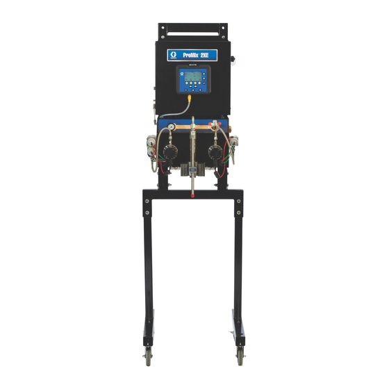
ProMix
Pump-Based Plural Component Proportioner
Self-contained, electronic two-component paint proportioner. For professional use only.
Important Safety Instructions
Read all warnings and instructions in this
manual. Save these instructions.
See pages 3-4 for model information, including maxi-
mum working pressure and approvals.
®
2KE
3A0868L
EN
ti15696a
Advertisement
Chapters
Table of Contents
Troubleshooting

Subscribe to Our Youtube Channel
Related Manuals for Graco ProMix 2KE


Summary of Contents for Graco ProMix 2KE
- Page 1 Operation ® ProMix 3A0868L Pump-Based Plural Component Proportioner Self-contained, electronic two-component paint proportioner. For professional use only. Important Safety Instructions Read all warnings and instructions in this manual. Save these instructions. See pages 3-4 for model information, including maxi- mum working pressure and approvals. ti15696a...
-
Page 2: Table Of Contents
Spraying ......34 Graco Standard Warranty ....76 Purging . -
Page 3: Models
2300 (15.8, 158) Acid ProMix 2KE hazardous location equipment manufactured in the United States, with serial number beginning with A or 01, has ATEX, FM, and CE approvals, as noted. Equipment manufactured in Belgium, with serial number beginning with M or 38, has ATEX and CE approvals, as noted. -
Page 4: Related Manuals
2300 (15.8, 158) Acid ProMix 2KE non-hazardous location equipment manufactured in the United States, with serial number beginning with A or 01, has FM and CE approvals. Equipment manufactured in Belgium, with serial number beginning with M or 38, has CE approval. -
Page 5: Warnings
Warnings Warnings The following warnings are for the setup, use, grounding, maintenance, and repair of this equipment. The exclama- tion point symbol alerts you to a general warning and the hazard symbols refer to procedure-specific risks. When these symbols appear in the body of this manual, refer back to these Warnings. Product-specific hazard symbols and warnings not covered in this section may appear throughout the body of this manual where applicable. - Page 6 Warnings WARNING INTRINSIC SAFETY Intrinsically safe equipment that is installed improperly or connected to non-intrinsically safe equipment will create a hazardous condition and can cause fire, explosion, or electric shock. Follow local regulations and the following safety requirements. • Only models with model numbers 24F102-24F115 and 24Z018, utilizing the air-driven alternator, are approved for installation in a Hazardous (explosive atmosphere) Location.
- Page 7 Warnings WARNING EQUIPMENT MISUSE HAZARD Misuse can cause death or serious injury. • Do not operate the unit when fatigued or under the influence of drugs or alcohol. • Do not exceed the maximum working pressure or temperature rating of the lowest rated system component.
-
Page 8: Important Two-Component Material Information
Important Two-Component Material Information Important Two-Component Material Information Material Self-ignition Isocyanates (ISO) are catalysts used in two component materials. Isocyanate Conditions Some materials may become self-igniting if applied too thick. Read material manufacturer’s warnings and Safety Data Sheet (SDS). Spraying or dispensing materials that contain isocyanates creates potentially harmful mists, Keep Components A and B vapors, and atomized particulates. -
Page 9: Moisture Sensitivity Of Isocyanates
Important Two-Component Material Information Moisture Sensitivity of NOTE: The amount of film formation and rate of crystal- lization varies depending on the blend of ISO, the Isocyanates humidity, and the temperature. Exposure to moisture (such as humidity) will cause ISO Changing Materials to partially cure;... -
Page 10: Important Acid Catalyst Information
Important Acid Catalyst Information Important Acid Catalyst Information The 2KE Plural Component Proportioner is designed for acid catalysts (“acid”) currently used in two-component, wood-finishing materials. Current acids in use (with pH levels as low as 1) are more corrosive than earlier acids. More corrosion-resistant wetted materials of construction are required, and must be used without substitution, to withstand the increased corrosive properties of these acids. -
Page 11: Glossary Of Terms
Glossary of Terms Glossary of Terms Dose Size - the amount of resin (A) and catalyst (B) that Potlife Time - the amount of time before a material is dispensed into an integrator. becomes unsprayable. Dose Time Alarm - the amount of time that is allowed Potlife Volume - the amount of material that is required for a dose to occur before an alarm occurs. -
Page 12: Overview
Overview Overview Usage The ProMix 2KE is an electronic two-component paint • Can proportion at ratios from 0.1:1 to 30.0:1. proportioner. It can blend most two-component paints. It is not for use with quick-setting paints (those with a pot •... -
Page 13: Intrinsically Safe Installation Requirements
Installation Intrinsically Safe Installation Requirements 1. The installation must meet the requirements of the National Electric Code, NFPA 70, Article 504 Resp., Article 505, and ANSI/ISA 12.06.01. Do not substitute or modify system components as 2. Multiple earthing of components is allowed only if this may impair intrinsic safety. - Page 14 Installation Non-Hazardous Locations USER INTERFACE 10' CAN CABLE MODULE 50' OPTION USB MODULE LINE POWER POWER FILTER SUPPLY FLUID CAN CABLE CONTROL MODULE LINEAR SENSOR/ LINEAR SENSOR/ REED SWITCH CABLE REED SWITCH CABLE "A" REED "B" REED SWITCH SWITCH "B" LINEAR "A"...
-
Page 15: Display Module
Gun, a shutoff ti16580a valve must be installed in the gun air line to shutoff the atomizing and turbine air to the gun. Contact your Graco distributor for information on air shutoff valves • Wall Power Systems for electrostatic applications. -
Page 16: Fluid Supply
See the System Pneumatic Schematic on page 68 (hazardous location) or page 69 (non-hazardous loca- Requirements tion). 1. Tighten all ProMix 2KE system air and fluid line con- nections as they may have loosened during ship- • Do not exceed the pressure rating of the lowest ment. - Page 17 Installation Component Solvent inlet Remove plug; Inlet recirculation outlet. ti16755a ti16754a ti15697a Key: Component A Pump Component B Pump DVA Component A Dose Valve DVB Component B Dose Valve SVA Solvent Valve A SVB Solvent Valve B Mix Manifold . 5. Fluid Connections 3A0868L...
-
Page 18: Tubing Chart And Diagrams
Installation Tubing Chart and Diagrams Type Color Description Starting Point Ending Point Tube OD in. (mm) Green Solvent Valve A On 0.156 (4.0) Green Dose Valve A On 0.156 (4.0) Green Solvent Valve B On 0.156 (4.0) Green Dose Valve B On 0.156 (4.0) Solvent Valve A Off 0.156 (4.0) - Page 19 Installation GFB1-A ATOM-1 ATOM-2 A Side B Side ti16772a A Side B Side ti16765a ti16766a See Manual 312784 for full setup instructions for a gun flush box. B Side A Side ti16764a 3A0868L...
-
Page 20: Electrical
Ground traffic areas in conduit to prevent damage from paint, solvent, and traffic. Neutral The ProMix 2KE operates with 85-250 VAC, 50/60 Hz ti16391a input power, with a maximum of 2 amp current draw. . 6. Control Box Electrical Connection The power supply circuit must be protected with a 15 amp maximum circuit breaker. -
Page 21: Grounding
• Non-Electrostatic: Ground the spray gun through Connect the ProMix 2KE ground wire to the ground connection to a Graco-approved grounded fluid sup- screw. Connect the clamp to a true earth ground. If wall ply hose. - Page 22 Installation Key: Control Box ground screw Control Box ground wire Pump B ground screw Pump B ground wire Pump A ground screw Pump A ground wire Gun Flush Box ground screw Gun Flush Box ground wire True Earth Ground - check your local code for requirements.
-
Page 23: Display Module
Display Module Display Module Error code Potlife state Screen number Active recipe Ratio Operation mode; see page 24 for key LCD display Potlife timers Navigation keys Flow rate Enter key Soft keys Navigation keys Error Reset Standby key ti16319a Setup key . -
Page 24: Icon Key
Display Module Icon Key The following tables present a printable version of the information on the ProMix 2KE icon card. See Table 3, page 54, for a printable version of the error code information on the reverse side of the card. -
Page 25: Screen Summary
Display Module Screen Summary NOTE: This summary is a one-page guide to the ProMix 2KE screens, followed by screen maps. For operating instructions, see Basic Operation, page 31. For further detail on individual screens, see Run Mode Details, page 41, or Setup Mode Details, page 44. -
Page 26: Ranges For User Inputs
Display Module Ranges for User Inputs This table is a one-sheet reference of the data range/options accepted for each user input and the default setting. See the page indicated in the table for further screen information, if needed. Page Screen User Input Range/Options Default... - Page 27 Display Module . 11. Run Mode Screen Map 3A0868L...
- Page 28 Display Module . 12. Setup Mode Screen Map, page 1 3A0868L...
- Page 29 Display Module . 13. Setup Mode Screen Map, page 2 3A0868L...
- Page 30 Display Module Password Set Password to 9909 (See Configure 3, Screen 20), then enter it here. Press to exit Setup. Press reenter Setup. Setup Home (Screen 17) displays, with Troubleshooting options. System Outputs 1 Set-Up Home System Inputs Screen Screen Push to enter forced mode, (System Outputs 2) System Outputs 2...
-
Page 31: Basic Operation
. 15. Power Switch tions are tight and installed according to the man- ual instructions. Fluid supply containers filled 2. Graco logo will display after five seconds, followed by Run Mix Spray (Screen 2). Check component A and B and solvent supply containers. -
Page 32: Prime The System
Basic Operation Prime the System 8. Open the fluid supply valve to the pump. NOTE: See Run Mode Details, pages 41-43, for further NOTE: If using an electrostatic gun, screen information, if needed. shut off the electrostatics before spraying. 9. If using a gun flush box, place the gun in the box and close the lid. -
Page 33: Pump Calibration
Basic Operation Pump Calibration 6. Press to start the calibration on the checked NOTE: See Calibration 1 and 2 (Screens 22 and 23), pump (A or B). Press to cancel the calibration. page 48, for further screen information, if needed. 7. -
Page 34: Spraying
Basic Operation 10. After the volume for A or B is entered, the ProMix If the fluid flow rate is too low: increase air pres- 2KE controller calculates the new pump factor and sure to component A and B fluid supplies or shows it on Calibration 1 (Screen 22) and Calibra- increase the regulated fluid pressure of mixed tion 2 (Screen 23). - Page 35 Basic Operation Purging Mixed Material 11. Adjust the solvent supply regulator back to its nor- mal operating pressure. There are times when you only want to purge the fluid manifold, such as: NOTE: The system remains full of solvent. • end of potlife NOTE: If your system uses 2 guns, you must trigger •...
- Page 36 Basic Operation 11. Disconnect the solvent supply lines and reconnect • The potlife on a material has expired and has not the component A and B fluid supplies. been flushed for 2 minutes. NOTE: The system remains full of solvent. If all of these conditions are met the system will auto- matically perform a purge and remove the expired mate- Autodump Purge...
-
Page 37: Pressure Relief Procedure
2. Close main air shutoff valve on air supply line and ware is changed. on ProMix 2KE. 3. Non-IS Systems: Shut off ProMix 2KE power If you change one of these inputs, the system locks so (0 position). that you cannot spray or mix. If you have changed to a meter system, the system also locks if you change the dosing type or the number of colors. -
Page 38: Use Of Optional Usb Module
Use of Optional USB Module Use of Optional USB Module USB Logs NOTE: User Number, Ratio, and Alarm 1-5 are dis- played as of 2KE System Software version 1.03.001 (USB Cube Software version 1.10.001). Job duration, Job Log 1 target ratio, actual ratio, and total purge volume are dis- played as of 2KE System Software version 1.06.001 See example in F . -
Page 39: Setup
Use of Optional USB Module . 23. Sample Error Log Setup Language dropdown The only setup required is to select the language in menu which you want to view the downloaded data. (Screens are icon-based and do not change.) Navigate to Config- ure 3 (Screen 20). -
Page 40: Download Procedure
It is recommended that users use the 4GB USB flash drive (16A004) available for purchase separately from Graco. If preferred, users may use one of the following 4 GB or less USB flash drives (not available from To help prevent fire and explosion, never leave the Graco). -
Page 41: Run Mode Details
Run Mode Details Run Mode Details Run Mix Spray (Screen 2) • Press a soft key button to select one of the main Run Mode screen sections: Mix , Errors Run Mix Spray (Screen 2) displays at startup or if or Pump Control is selected from Run Home (Screen 1). -
Page 42: Run Mix Totals (Screen 4)
Run Mode Details Run Mix Totals (Screen 4) Run Job Number (Screen 38) Run Mix Totals (Screen 4) displays if is selected Run Job Number (Screen 38) displays if from the Run Mix Batch Screen. Use this screen to view selected from the Run Mix Totals Screen. -
Page 43: Run Log Errors (Screens 5-14)
Run Mode Details Run Log Errors (Screens 5-14) Run Pump Control (Screen 15) Run Log Errors (Screens 5-14) display if Run Pump Control (Screen 15) displays if selected from Run Home (Screen 1). It displays the last selected from the Run Home Screen. Use this screen to 50 errors in the log. -
Page 44: Setup Mode Details
Setup Mode Details Setup Mode Details Press on any screen to enter the Setup screens. If the system has a password lock, Password (Screen 16) Software Version: displays. If the system is not locked (password is set to Display Module 0000), Setup Home (Screen 17) displays. -
Page 45: Configure 1-4 (Screens 18-21)
Setup Mode Details Configure 1-4 (Screens 18-21) Configure 1 (Screen 18) displays if is selected on Setup Home (Screen 17). This screen allows users to set up the system type (pump or meter) and number of guns (1 or 2). NOTE: If 1 gun is selected, users can enable a gun flush box (=yes;... -
Page 46: Recipe 1-1 (Screen 28)
Setup Mode Details Configure 3 (Screen 20) allows users to set preferred Recipe 1-2 (Screen 29) language (for optional USB Module), date format, date, time, password (0000 to 9999), and number of minutes Note about Settings of 0: If a Flush time is set to 0, (0 to 99) of inactivity required before the backlight turns that valve will not flush. -
Page 47: Maintenance 1-3 (Screens 24-26)
Setup Mode Details Maintenance 1-3 (Screens 24-26) Maintenance Recommendations The following table shows recommended starting values Maintenance 1 (Screen 24) displays if is selected for maintenance. Maintenance needs will vary based on on Setup Home (Screen 17). The Maintenance Screens individual applications and material differences. -
Page 48: Calibration 1 And 2 (Screens 22 And 23)
Setup Mode Details Calibration 1 and 2 (Screens 22 • Press to highlight the pump you wish to cali- and 23) brate. Press . An X displays in the box. NOTE: See Pump Calibration, page 33, for detailed • Press to start the calibration on the highlighted instructions. - Page 49 Setup Mode Details Troubleshooting System Inputs (Screen 35) Troubleshooting System Outputs (Screen 37) From Setup Home (Screen 17) with Troubleshooting From Setup Home (Screen 17) with Troubleshooting active, press to display Troubleshooting System Inputs (Screen 35). An X displays in the box to indicate if active, press to display Troubleshooting System Pump B is up or down, if Pump A is up or down, if Air...
-
Page 50: Dynamic Dosing
Setup Mode Details Dynamic Dosing In typical operation (ratios 1:1 and above), component A Balancing A/B Pressure dispenses constantly. Component B dispenses intermit- If component B pressure is too high, it will push the com- tently in the necessary volume to attain the mix ratio. ponent A stream aside during B injection. - Page 51 Setup Mode Details B Pressure B Pressure Too Low Too Low B Pressure Too High B Pressure Too High A Pressure B Pressure A Pressure B Pressure . 50. A/B Control Range with Properly Sized Restrictor NOTE: If the restrictor is too small, it may be necessary to supply more differential pressure than is available in your system.
-
Page 52: System Errors
Air or Air-assisted Guns The air flow switch (AFS) detects air flow to the gun and signals the ProMix 2KE controller when the gun is trig- gered. The gun icon on the Display Module shows spray when the AFS is activated. -
Page 53: System Idle Warning (Idle)
System Errors System Idle Warning (IDLE) This warning occurs if the ProMix is set to Mix and 2 minutes have elapsed since the system last received the air flow switch signal (gun trigger). The Gun Idle icon is displayed. This warning is not active in systems with a 45:1 pump ratio, using an airless gun. -
Page 54: Error Codes
System Errors Error Codes Table 3: System Alarm/Advisory/Record Codes Table 3: System Alarm/Advisory/Record Codes Code Description Details Code Description Details Advisory Codes - No alarm, system continues operat- Alarm Codes - Alarm sounds, system stops, icon dis- ing, icon displays on active screen until cleared plays until problem is solved and alarm is cleared. -
Page 55: Alarm Troubleshooting
System Errors Alarm Troubleshooting Alarm and Description Cause Solution The CAN cable between the Display Mod- Verify that the cable is correctly Communication Error ule and the Advanced Fluid Control Module connected. The Display Module is not is not connected. communicating with the The CAN cable is cut or bent. -
Page 56: Equ2
System Errors Alarm and Description Cause Solution EQU2 Most USB drives do not conform to IS stan- Put system in Standby. Insert the USB Drive Error dards, so it is hazardous to use one while USB drive only in a non-hazardous The USB drive has been the system is running. -
Page 57: Sfa1 Sfb1
System Errors Alarm and Description Cause Solution SFA1 or SFB1 Check components and clean, repair, Gun, line, or valve is plugged or stuck. PreMix Error or replace as necessary. In systems with a gun flush Refill fluid supply. Check and repair Pump(s) not working or out of fluid. -
Page 58: R1 Ratio Low Error
Slow actuation of the component A or B Manually operate the Dose Valve A valves. This can be caused by: and B solenoid valves as instructed in the ProMix 2KE Repair-Parts manual to check operation. • Air pressure to the valve actuators is •... -
Page 59: R4 Ratio High Error
System Errors Alarm and Description Cause Solution There is too little restriction in the system. • Check that the system is fully Ratio High Error loaded with material. The mix ratio is higher than • Check that the supply pump’s the set tolerance for an A to B cycle rate is set properly. -
Page 60: Qta1 Qtb1
System Errors Alarm and Description Cause Solution QTA1 or QTB1 System is in Mix mode and gun is only par- Fully trigger the gun. Dose Time Error tially triggered, allowing air but no fluid to The gun trigger is active, but pass through gun. -
Page 61: Efa1 Efb1
System Errors Alarm and Description Cause Solution EFA1 or EFB1 Trigger gun and allow fluid to flow Gun not open. Park Error while pump is attempting to park. Pump A (EFA1) or Pump B Check and clear all fluid lines, gun tip, Fluid lines plugged. -
Page 62: Dynamic Dosing Restrictor Selection Graphs
Dynamic Dosing Restrictor Selection Graphs Dynamic Dosing Restrictor Selection Graphs Use the graphs on pages 63- 67 as a guide to determine the correct restrictor size for your desired flow and mate- Table 4: Restrictor Sizes rial viscosity. Table 4 lists the available restrictor sizes. Size Code Orifice Size Part No. - Page 63 Dynamic Dosing Restrictor Selection Graphs (bar, MPa) 4000 (276, 27.6) 3500 (241, 24.1) #2 Restrictor #3 Restrictor 3000 #4 Restrictor (207, 20.7) #7 Restrictor 2500 (172, 17.2) 2000 (138, 13.8) 1500 (103, 10.3) 1000 (69, 6.9) (34, 3.4) 1000 1500 2000 2500 3000...
- Page 64 Dynamic Dosing Restrictor Selection Graphs (bar, MPa) 1400 (97, 9.7) 1200 (83, 8.3) #2 Restrictor #3 Restrictor 1000 #4 Restrictor (69, 6.9) #7 Restrictor (55, 5.5) (41, 4.1) (28, 2.8) 14, 1.4) 1000 1500 2000 2500 3000 3500 4000 Flow Rate (cc/min) Detail View (28, 2.8) (21, 2.1)
- Page 65 Dynamic Dosing Restrictor Selection Graphs (bar, MPa) (55, 5.5) #2 Restrictor (48, 4.8) #3 Restrictor #4 Restrictor #7 Restrictor (41, 4.1) (34, 3.4) (28, 2.8) (21, 2.1) (14, 1.4) (7, 0.7) 1000 1500 2000 2500 3000 3500 4000 Flow Rate (cc/min) Detail View (14, 1.4) (10, 1.0)
- Page 66 Dynamic Dosing Restrictor Selection Graphs (bar, MPa) (21, 2.1) (17.2, 1.72) #2 Restrictor #3 Restrictor #4 Restrictor #7 Restrictor (14, 1.4) 10.3, 1.03) (7.0, 0.7) (3.4, 0.34) 1000 1500 2000 2500 3000 3500 4000 Flow Rate (cc/min) Detail View (7, 0.7) (5.2, 0.52) (3.4, 0.34) (1.7, 0.17)
- Page 67 Dynamic Dosing Restrictor Selection Graphs (bar, MPa) (14, 1.4 (12.4, 1.2 #2 Restrictor #3 Restrictor (11, 1.1) #4 Restrictor #7 Restrictor 9.7, 0.9) 8.3, 0.8) (7, 0.7) (5.5, 0.55) (4.1, 0.41) (2.8, 0.28) (1.4, 0.14) 1000 1500 2000 2500 3000 3500 4000 Flow Rate (cc/min)
-
Page 68: Schematics
Schematics Schematics Hazardous Location System Pneumatic Schematic 3A0868L... - Page 69 Schematics Non-Hazardous Location Pneumatic Schematic 3A0868L...
- Page 70 Schematics Hazardous Location Electrical Schematic CAN_L +V_CAN V_CAN_RTN CAN_H SHIELD UNUSED ALTERNATOR 18 PSI CAN_L CAN_L UNUSED MODULE +V_CAN +V_CAN 1.5 FCM UNUSED V_CAN_RTN V_CAN_RTN UNUSED (MIN) CAN_H CAN_H UNUSED SHIELD SHIELD V CAN CAN_L USB COMPONENT USB BASE V CAN +V_CAN MODULE V CAN...
- Page 71 Schematics Hazardous Location Electrical Schematic (continued) UNUSED CAN_L UNUSED +V_CAN UNUSED V_CAN_RTN UNUSED CAN_H UNUSED SHIELD FLUID CONTROL UNUSED UNUSED MODULE AFS #1 (+) ALARM (+) COMMON COMMON PURGE B (+) PURGE A (+) DOSE A1 (+) DOSE B (+) +12 VDC +12 VDC FLOW METER B SIG...
- Page 72 Schematics Non-Hazardous Location Electrical Schematic CAN_L TERMINAL +V_CAN BLOCK V_CAN_RTN CAN_H GRND SHIELD POWER SUPPLY GRND LINE POWER FILTER CAN_L CAN_L +V_CAN +V_CAN V_CAN_RTN V_CAN_RTN CAN_H CAN_H SWITCH SHIELD SHIELD ROCKER V CAN USB COMPONENT USB BASE V CAN MODULE V CAN MODULE V CAN RTN...
- Page 73 Schematics Non-Hazardous Electrical Schematic (continued) CAN_L CAN_L +V_CAN +V_CAN FLUID V_CAN_RTN V_CAN_RTN CAN_H CAN_H CONTROL SHIELD SHIELD MODULE UNUSED UNUSED ALARM (+) AFS #1 (+) COMMON COMMON PURGE A (+) PURGE B (+) DOSE A1 (+) DOSE B (+) +12 VDC +12 VDC FLOW METER B SIG FLOW METER A SIG...
-
Page 74: Dimensions And Mounting
Dimensions and Mounting Dimensions and Mounting 14.76 in. (37 cm) 1.0 in 0.55 in (2.5 cm) 12.76 in. (1.4 cm) (32 cm) Depth: 18.0 in. (46 cm) 33.5 in. (85 cm) 44.5 in. (113 cm) Merkur: 57 in. (145 cm) Merkur Bellows: 65 in. -
Page 75: Technical Data
0.5 to 0.7 MPa, 5.2 to 7 bar Air filter inlet size 3/8 npt(f) Air filtration for air logic (Graco-supplied) 5 micron (minimum) filtration required; clean and dry air Air filtration for atomizing air (user-supplied) 30 micron (minimum) filtration required; clean and dry air Mixing ratio range 0.1:1 to 30:1... -
Page 76: Graco Standard Warranty
With the exception of any special, extended, or limited warranty published by Graco, Graco will, for a period of twelve months from the date of sale, repair or replace any part of the equipment determined by Graco to be defective.
Need help?
Do you have a question about the ProMix 2KE and is the answer not in the manual?
Questions and answers