Festo CPX Series Electronic Manual
Hide thumbs
Also See for CPX Series:
- Manual (446 pages) ,
- Electronic manual (232 pages) ,
- Description (156 pages)
Table of Contents
Advertisement
Quick Links
CPX terminal
Electronics manual
CPX I/O modules
Pneumatic
interfaces types
VMPA−FB−EPL−...
CPX−GP−03−4.0
CPX−GP−CPA−...
MPA pneumatic
modules with
electronic modules
types
VMPA1−FB−EM..−8
VMPA2−FB−EM..−4
I/O modules types
CPX−8DE
CPX−4DE
CPX−4DA
CPX−8DE−8DA
Sub−bases types
CPX−AB−...
Manual
526 440
en 0405b
[684 299]
Advertisement
Chapters
Table of Contents

Related Manuals for Festo CPX Series


Summary of Contents for Festo CPX Series
- Page 1 CPX terminal Electronics manual CPX I/O modules Pneumatic interfaces types VMPA−FB−EPL−... CPX−GP−03−4.0 CPX−GP−CPA−... MPA pneumatic modules with electronic modules types VMPA1−FB−EM..−8 VMPA2−FB−EM..−4 I/O modules types CPX−8DE CPX−4DE CPX−4DA CPX−8DE−8DA Sub−bases types CPX−AB−... Manual 526 440 en 0405b [684 299]...
- Page 3 ....... . . 526 440 E (Festo AG & Co. KG, D 73726 Esslingen, Federal Republic of Germany, 2004) Internet: http://www.festo.com...
- Page 4 WAGO Kontakttechnik GmbH, 32385 Minden, Germany TORX® is a registered trade name of CAMCAR TEXTRON INC., Rockford, Ill., USA HARAX® is a registered trade name of HARTING Deutschland GmbH & Co. KG, 32381 Minden, Germany Festo P.BE−CPX−EA−E N en 0405b...
-
Page 5: Table Of Contents
..........2−19 2.5.3 Fault treatment and parametrizing ......2−22 Festo P.BE−CPX−EA−E N en 0405b... - Page 6 ..........5−16 5.5.3 Fault treatment and parametrizing ......5−18 Festo P.BE−CPX−EA−E N en 0405b...
- Page 7 ............B−1 Festo P.BE−CPX−EA−E N en 0405b...
- Page 8 Contents and general instructions Festo P.BE−CPX−EA−E N en 0405b...
-
Page 9: Designated Use
Designated use The CPX pneumatic interfaces, MPA pneumatic modules and CPX I/O modules described in this documentation are in tended exclusively for use in conjunction with Festo CPX ter minals. The pneumatic interfaces and modules may only be used as follows:... -
Page 10: Target Group
(PLC) and field bus systems. Service Please consult your local Festo repair service if you have any technical problems. VIII Festo P.BE−CPX−EA−E N en 0405b... -
Page 11: Important User Instructions
This means that failure to observe this instruction may result in damage to property. The following pictogram marks passages in the text which describe activities with electrostatically sensitive compo nents. Electrostatically sensitive components may be damaged if they are not handled correctly. Festo P.BE−CPX−EA−E N en 0405b... - Page 12 Accessories: Information on necessary or sensible accessories for the Festo product. Environment: Information on environment−friendly use of Festo products. Text markings The bullet indicates activities which may be carried out in · any order. 1. Figures denote activities which must be carried out in the numerical order specified.
-
Page 13: Notes On The Use Of This Manual
These appear in English on the handheld type CPX−MMI−1. [..] In this manual the data and parameters shown on the hand held in English are framed in the text, e.g. [Debounce time]. The translation then follows, e.g.: [Debounce time] Festo P.BE−CPX−EA−E N en 0405b... -
Page 14: Cpx Pneumatic Interfaces
CPX−GP−CPA−10 CPX pneumatic interface Pneumatic interface for for CPA10 connecting the modular electric peripherals CPX−GP−CPA−14 CPX pneumatic interface type 50 (CPX) to valve for CPA14 terminals type 12 (CPA) Tab. 0/1: Overview of pneumatic interfaces Festo P.BE−CPX−EA−E N en 0405b... -
Page 15: Mpa Pneumatic Modules
4 outputs (valve solenoid coils) without electrical isolation VMPA2−FB−AP−2−1 sub−base for 2 valve plates, VMPA2−M1H−... valve plates (or corresponding pneumatic components) or VMPA2−RP cover plates for reserve locations. Tab. 0/2: Overview of MPA pneumatic modules XIII Festo P.BE−CPX−EA−E N en 0405b... -
Page 16: Cpx I/O Modules
CPX−AB−4−M12x2−5POL CPX−4DA Output module CPX−AB−8−M8−3POL with 4 outputs, CPX−AB−8−KL−4POL CPX−AB−1−SUB−BU−25POL CPX−AB−4−HARX2−4POL CPX−AB−4−M12−8POL Interlinking modules: CPX−8DE−8DA Multi I/O module CPX−GE−EV (input/output CPX−GE−EV−... module) with 8 inputs and 8 outputs, PNP Tab. 0/3: Overview of I/O modules Festo P.BE−CPX−EA−E N en 0405b... -
Page 17: Diagnosis Via The Field Bus
These faults can be evaluated via the: status bits (system status) I/O diagnostic interface (system diagnosis) module diagnosis fault numbers Further information on diagnosis can be found in the CPX system manual and in the manual for the field bus node. Festo P.BE−CPX−EA−E N en 0405b... -
Page 18: Setting Up A Cpx Terminal
Field bus node Manifold sub−base with additional supply I/O modules Manifold sub−base without supply Pneumatic interface Manifold sub−base with system supply Pneumatic modules End plate (example CPA type 12) Fig. 0/1: Example of CPX terminal Festo P.BE−CPX−EA−E N en 0405b... - Page 19 CPA pneumatics" sioning CPA pneumatics (type 12) type P.BE−CPA−... Valve terminals with Instructions on fitting, installing and commis Midi/Maxi pneumatics" sioning Midi/Maxi pneumatics (type 03) type P.BE−MIDI/MAXI−03−... Tab. 0/4: Manuals on the CPX terminal XVII Festo P.BE−CPX−EA−E N en 0405b...
- Page 20 The pneumatic interface is the interface between the modular electrical peripherals and the pneumatics. Status bits Internal inputs which supply coded common diagnostic messages. Sub−base Exchangeable upper part of housing of modules with connection techniques. Tab. 0/5: Product−specific abbreviations XVIII Festo P.BE−CPX−EA−E N en 0405b...
-
Page 21: Pneumatic Interfaces
Pneumatic interfaces Chapter 1 Type VMPA−FB−EPL−... CPX−GP−03−4.0 CPX−GP−CPA−10 CPX−GP−CPA−14 1−1 Festo P.BE−CPX−EA−E N en 0405b... - Page 22 ..........1−21 1.6.3 Fault treatment and parametrizing ......1−23 1−2 Festo P.BE−CPX−EA−E N en 0405b...
- Page 23 Information on the pneumatics of the CPX terminal can be found in the relevant pneumatics manual. Information on the address assignment as well as on commis sioning can be found in the relevant manual for the field bus node or the function module. 1−3 Festo P.BE−CPX−EA−E N en 0405b...
- Page 24 12 of size 10 (CPA10). CPX−GP−CPA−14 Pneumatic interface for connecting the modular electric peripherals type 50 (CPX) to valve terminals type 12 of size 14 (CPA14). Tab. 1/1: Overview of pneumatic interfaces 1−4 Festo P.BE−CPX−EA−E N en 0405b...
- Page 25 From a technical point of view, the pneumatic interfaces for or CPA pneumatics Midi/Maxi pneumatics or CPA pneumatics represent an elec tric module with a variable (configurable) number of digital outputs for controlling the fitted valves (see chapter follow ing sections). 1−5 Festo P.BE−CPX−EA−E N en 0405b...
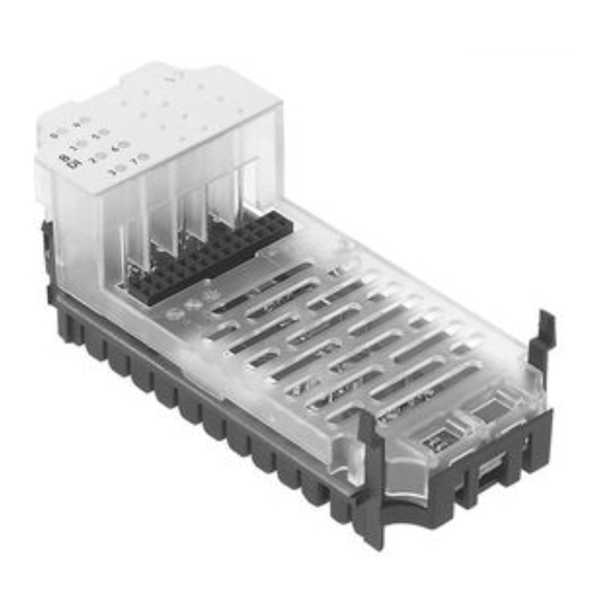
- Page 26 Connecting plug for the MPA pneumatic modules Inscription field Connecting plug for the CPX manifold sub−bases Fig. 1/1: Display and connecting elements of the pneumatic interface for MPA pneumatics 1−6 Festo P.BE−CPX−EA−E N en 0405b...
-
Page 27: Pneumatic Interface
CPX manifold sub−bases Fig. 1/2: Display and connecting elements of the pneumatic interfaces for Midi/Maxi or CPA pneumatics Use the identification signs type IBS 6x10 for marking on the pneumatic interface for CPA pneumatics. 1−7 Festo P.BE−CPX−EA−E N en 0405b... -
Page 28: Fitting
The setting of the DIL switches on the pneumatic interfaces for Midi/Maxi or CPA pneumatics for the configuration of the pneumatics (valves used) can be undertaken on the fitted CPX terminal. 1−8 Festo P.BE−CPX−EA−E N en 0405b... -
Page 29: Settings For Configuring The Pneumatics
Before carrying out installation and/or maintenance work, switch off the following: the compressed air supply the operating and load voltage supplies. 1−9 Festo P.BE−CPX−EA−E N en 0405b... - Page 30 CPA pneumatic interface has been designed for at least 10 fitting/dismantling cycles. Removing the cover 1. Loosen the screws in the cover with a Torx screwdriver size T10. 2. Carefully lift up the cover. 1−10 Festo P.BE−CPX−EA−E N en 0405b...
- Page 31 8 further output addresses per switch element are reserved for valves in the address range. Decisive for the assigned address range is the setting of the higher−value DIL switch in the position ON (closed). 1−11 Festo P.BE−CPX−EA−E N en 0405b...
- Page 32 26 can be used 3: as desired 2: as desired 1: as desired Depending on CPX equipment and field bus node, see following note. Additionally assigned output addresses remain unused. Tab. 1/2: DIL switch setting 1−12 Festo P.BE−CPX−EA−E N en 0405b...
- Page 33 Pneumatic interface Tightening torque Midi/Maxi (type CPX−GP−03−4.0) 1.0 ... 1.3 Nm CPA (type CPX−GP−CPA−..) 0.9 ... 1.1 Nm Tab. 1/3: Tightening torques for the pneumatic interfaces 1−13 Festo P.BE−CPX−EA−E N en 0405b...
-
Page 34: Installation
Instructions on assigning the addresses to the individual valve solenoid coils with MPA pneumatic modules can be found in chapter 2. Protection class When fitted completely, the pneumatic interfaces with valve terminal pneumatics comply with protection class IP65 (see appendix A.1). 1−14 Festo P.BE−CPX−EA−E N en 0405b... -
Page 35: Commissioning Instructions
If the wire fracture monitoring is activated for an output which does not have a valve solenoid coil, the CPX terminal will register the fault Wire fracture" when it is switched on, due to the alleged defective valve solenoid coil. 1−15 Festo P.BE−CPX−EA−E N en 0405b... - Page 36 1 = active [Active] 0 = inactive [Inactive] Presetting: bit 2: active bit 3: inactive Note Monitoring can also be set for the complete CPX terminal (see CPX system manual). Tab. 1/4: Monitoring the CPX module 1−16 Festo P.BE−CPX−EA−E N en 0405b...
- Page 37 With the so−called Fail−safe parametrizing, you can defines the signal status which outputs should assume in the event of field bus communication faults (see also CPX system manual). Tab. 1/6: Fail safe channel x (channel−specific) 1−17 Festo P.BE−CPX−EA−E N en 0405b...
- Page 38 Force state outputs channel x: Set signal Reset signal (presetting) Note The function Force enables the manipulation of signal states disconnected from actual operating states (see also CPX system manual). Tab. 1/8: Force channel x (channel−specific) 1−18 Festo P.BE−CPX−EA−E N en 0405b...
-
Page 39: Diagnosis
With the MPA pneumatics, diagnosis takes place via the individual MPA pneumatic modules (module−orientated, see chapter 2). 1−19 Festo P.BE−CPX−EA−E N en 0405b... -
Page 40: Fault Messages Of The Pneumatic Interfaces
Tolerance range of the load voltage supply V see Technical Specifications in the Appendix.. Number of the faulty channel:see module diagnostic data. Tab. 1/9: Fault messages of the pneumatic interfaces for Midi/Maxi or CPA pneumatics 1−20 Festo P.BE−CPX−EA−E N en 0405b... -
Page 41: Led Display
There is an LED under the transparent cover of the pneu CPA pneumatics matic interfaces for diagnosing the pneumatic interfaces for Midi/Maxi or CPA pneumatics. CPX−GP−03−4.0 CPX−GP−CPA−... Fault LED (red) Fig. 1/4: LED display of the pneumatic interfaces 1−21 Festo P.BE−CPX−EA−E N en 0405b... - Page 42 (providing it is not parametrized otherwise). Status LEDs of the valve solenoid coils The yellow status LEDs on the valve solenoid coils show the status of the relevant output (see relevant pneumatics manual). 1−22 Festo P.BE−CPX−EA−E N en 0405b...
- Page 43 Module parameter (switch position represented = default setting) Module−specific fault Channel−specific fault (fault no. 13 only with CPA pneumatics) Fig. 1/5: Principle of fault treatment in the pneumatic interfaces for Midi/Maxi or CPA pneumatics 1−23 Festo P.BE−CPX−EA−E N en 0405b...
- Page 44 1. Pneumatic interfaces 1−24 Festo P.BE−CPX−EA−E N en 0405b...
- Page 45 MPA pneumatic modules Chapter 2 Electronik modules type VMPA1−FB−EMG−8 VMPA1−FB−EMS−8 VMPA2−FB−EMG−4 VMPA2−FB−EMS−4 2−1 Festo P.BE−CPX−EA−E N en 0405b...
- Page 46 ..........2−19 2.5.3 Fault treatment and parametrizing ......2−22 2−2 Festo P.BE−CPX−EA−E N en 0405b...
-
Page 47: Mpa Pneumatic Modules
Information on the address assignment as well as on commis sioning can be found in the relevant manual for the field bus node or the function module. 2−3 Festo P.BE−CPX−EA−E N en 0405b... -
Page 48: Function Of The Mpa Pneumatic Modules
VMPA2−FB−EM..−4 electronic module with 4 outputs (valve solenoid coils) VMPA2−FB−AP−2−1 sub−base for 2 valve plates, VMPA2−M1H−... valve plates (or corresponding pneumatic components) or VMPA2−RP cover plates for reserve locations. Tab. 2/1: MPA pneumatic modules 2−4 Festo P.BE−CPX−EA−E N en 0405b... - Page 49 VMPA2−FB−EMG−4 Electronic module with 4 out puts (valve solenoid coils), with electrical isolation VMPA2−FB−EMS−4 Electronic module with 4 out puts (valve solenoid coils), without electrical isolation Tab. 2/2: Overview of MPA electronic modules 2−5 Festo P.BE−CPX−EA−E N en 0405b...
-
Page 50: Display And Connecting Elements
Connecting plug for the CPX pneumatic interface or for further MPA pneu matic modules Fig. 2/2: Display and connecting elements (example MPA1) Use identification plate type VMPA1−ST−1−4 for labelling the MPA pneumatic modules. 2−6 Festo P.BE−CPX−EA−E N en 0405b... -
Page 51: Fitting
Do not touch the electrical contacts of the modules. · Observe the regulations for handling electrostatically · sensitive components. Discharge yourself of static electricity before fitting or · removing the modules in order to protect the modules against static discharges. 2−7 Festo P.BE−CPX−EA−E N en 0405b... - Page 52 2. Loosen the screws with which the electronic module is fastened to the sub−base. 3. Pull the electronic module upwards out of the body of the sub−base. 2−8 Festo P.BE−CPX−EA−E N en 0405b...
- Page 53 Identification plate Sealing rim of the electronic module Fastening screws of the electronic module 2 conical ring seals per valve plate or blanking plate Fig. 2/3: Dismantling and fitting the electronic module (example MPA1) 2−9 Festo P.BE−CPX−EA−E N en 0405b...
- Page 54 (see Fig. 2/3). 5. Place the components on the sub−base. 6. Screw the components at first slightly and then tighten with 0.2 ... 0.25 Nm. 2−10 Festo P.BE−CPX−EA−E N en 0405b...
-
Page 55: Installation
If your MPA pneumatics are fitted with electronic mod · ules of type VMPA1−FB−EMS−8 or VMPA2−FB−EMS−4, use only system supply module type CPX−GE−EV−S for sup plying the MPA pneumatics. 2−11 Festo P.BE−CPX−EA−E N en 0405b... - Page 56 VMPA1−FB−EMG−8 or VNPA2−FB−EMG−4, V and V el/sen completely electrically isolated. In conjunction with a mani fold sub−base with valve supply type CPX−GE−EV−V, it is poss ible to switch off the valve supply voltage at all poles. 2−12 Festo P.BE−CPX−EA−E N en 0405b...
- Page 57 5 further rails Fig. 2/4: Power supply circuit for MPA pneumatic modules Protection class When fitted completely, the MPA pneumatic modules comply with protection class IP65 (see appendix A.1). 2−13 Festo P.BE−CPX−EA−E N en 0405b...
- Page 58 (addresses Ox+5 unused) Addr. of coils 14 (channel 0, 2, 4, 6) Blanking plate Addr. of coils 12 (channel 1, 3, 5, 7) Fig. 2/5: Example: Address assignment of the MPA pneumatic modules (top view) 2−14 Festo P.BE−CPX−EA−E N en 0405b...
-
Page 59: Commissioning Instructions
Undervoltage at valves (V [Monitor Vval] Values 1 = active (presetting) [Active] 0 = inactive [Inactive] Note Monitoring can also be set for the complete CPX terminal (see CPX system manual). Tab. 2/3: Monitoring the CPX module 2−15 Festo P.BE−CPX−EA−E N en 0405b... - Page 60 With the so−called Idle mode parametrizing, you can define the signal status which outputs should assume when they change to the idle state (see also CPX system manual). This parameter is not available with all field bus protocols. Tab. 2/5: Idle mode channel x (channel−specific) 2−16 Festo P.BE−CPX−EA−E N en 0405b...
- Page 61 Force state outputs channel x: Set signal Reset signal (presetting) Note The Force function permits the manipulation of signal states disconnected from actual operating states (see also CPX system manual). Tab. 2/6: Force channel x (channel−specific) 2−17 Festo P.BE−CPX−EA−E N en 0405b...
-
Page 62: Diagnosis
Technical Specifications in the appendix Tab. 2/7: Fault messages of the MPA pneumatic modules Please note The fault in the load voltage for the valves is registered for the whole module as module fault with channel number 1. 2−18 Festo P.BE−CPX−EA−E N en 0405b... - Page 63 12 14 12 14 12 14 12 14 (here channel 0) Addresses and LED assignment of valve solenoid coils 12 Addresses and LED assignment of valve solenoid coils 14 Fig. 2/6: LED display of the MPA1 pneumatic modules 2−19 Festo P.BE−CPX−EA−E N en 0405b...
- Page 64 LEDs of valve solenoid coils 14 (here channel 0) Addresses and LED assignment of valve solenoid coils 12 Addresses and LED assignment of valve solenoid coils 14 Fig. 2/7: LED display of the MPA2 pneumatic modules 2−20 Festo P.BE−CPX−EA−E N en 0405b...
- Page 65 LED lights up Tab. 2/8: LEDs of the MPA pneumatic module The fault shown by the red LEDs is transmitted by the MPA pneumatic module to the field bus node (unless parametrized otherwise). 2−21 Festo P.BE−CPX−EA−E N en 0405b...
-
Page 66: Fault Treatment And Parametrizing
Monitoring Fault no. 5 Fault in load voltage for valves Module parameters (switch position represented = default setting) Module−specific fault Fig. 2/8: Principle of fault treatment and parametrizing in the MPA pneumatic module 2−22 Festo P.BE−CPX−EA−E N en 0405b... - Page 67 Overview and connecting technology I/O modules Chapter 3 Type CPX−AB−4−M12x2−5POL CPX−AB−8−M8−3POL CPX−AB−8−KL−4POL CPX−AB−1−SUB−BU−25POL CPX−AB−4−HARX2−4−POL CPX−AB−4−M12−8POL 3−1 Festo P.BE−CPX−EA−E N en 0405b...
- Page 68 Fitting the screening plates ....... . 3−22 3−2 Festo P.BE−CPX−EA−E N en 0405b...
- Page 69 CPX system manual. Information on the address assignment as well as on com missioning can be found in the relevant manual for the field bus node or the function module. 3−3 Festo P.BE−CPX−EA−EN en 0405b...
- Page 70 The manifold sub−base in the form of a lower housing part provides the mechanical and electrical link between the module and the valve terminal. Sub−base with special connections Electronic module Manifold sub−base Fig. 3/1: Components of an I/O module 3−4 Festo P.BE−CPX−EA−EN en 0405b...
- Page 71 Protection class IP65/IP67 CPX−AB−8−KL−4POL 2 terminal strips, 16−pin (4 x 4−pin) Protection class IP20 All cores individually spring−loaded Connections in groups of 4, one func tional earth connection per group Tab. 3/1: Connection techniques part 1 3−5 Festo P.BE−CPX−EA−EN en 0405b...
- Page 72 Protection class IP65/IP67 Intended for connecting cylinder− valve combination type DNCV Connections in groups, one functional earth connection per group Screening possibility via screening plate/shield (see Accessories, appen dix A.9) Tab. 3/2: Connection techniques part 2 3−6 Festo P.BE−CPX−EA−EN en 0405b...
- Page 73 (here 8DI for an input module type CPX−8DE) Electrical connections (example) Inscription fields for addresses LEDs: Inputs (green), Outputs (yellow), Fault (red) Fig. 3/2: Display and connecting elements Use inscription labels type IBS 6x10 for writing the addresses. 3−7 Festo P.BE−CPX−EA−EN en 0405b...
- Page 74 (1 sub−D socket, 25−pin) CPX−AB−4−HARX2−4POL · · · (4 M12 sockets with insulation piercing, 4−pin) CPX−AB−4−M12−8POL · (4 M12 sockets, 8−pin) Can be combined · Cannot be combined Tab. 3/3: Combinations of I/O modules and sub−bases 3−8 Festo P.BE−CPX−EA−EN en 0405b...
- Page 75 In structions can be found on the following pages and in the appendix A.6. Use plugs and cables from the Festo range for connecting sensors or actuators (see appendix A.9). 3−9...
- Page 76 In order that the completely fitted modules with sub−base CPX−AB−4−M12x2−5POL comply with protection class IP65/IP67: Use plugs and cables from the Festo range for connect · ing sensors or actuators (see appendix A.9). Tighten the union nuts of the plugs at first by hand.
- Page 77 DIN 46 245 B2,8−1 Fig. 3/3: Connecting the screening plate Please note In order to comply with protection class IP65/IP67: Do not use conical pressure springs if you seal unused · sockets with protective caps. 3−11 Festo P.BE−CPX−EA−EN en 0405b...
- Page 78 In order that the completely fitted modules with sub−base CPX−AB−8−M12x2−5POL comply with protection class IP65/IP67: Use plugs and cables from the Festo range for connect · ing sensors or actuators (see appendix A.9). Tighten the union nuts of the plugs at first by hand.
- Page 79 The cable clamp is then unlocked. 2. When the clamp is unlocked, you can push/pull the ends of the cable into/out of the clamp opening. 3. Pull the screwdriver out of the opening. The cable will then be clamped securely. 3−13 Festo P.BE−CPX−EA−EN en 0405b...
- Page 80 The completely fitted sub−base CPX−AB−1−SUB−BU−25POL complies with protection class IP20. In order that sub−base CPX−AB−1−SUB−BU−25POL complies with protection class IP65/IP67, use Festo plug type SD−SUB−D−ST25. When fitting the plug onto the sub−base note the maximum tightening torque of 0.5 Nm.
- Page 81 Please note In order that the completely fitted modules with sub−base CPX−AB−4−HARX2−4POL comply with protection class IP65/IP67: Use Festo plug type SEA−GS−HAR−4POL (consisting of · union nut, strain relief and splicing ring) for connecting sensors or actuators. Tighten the union nuts of the plugs at first by hand.
- Page 82 Loosen the screw connector and pull the core out of the · contacts. Reconnection after the cores have been cut is possible for up to 10 times (if the same core diameter is used). Cut off the cable ends and repeat points 2 to 4. 3−16 Festo P.BE−CPX−EA−EN en 0405b...
- Page 83 Please note In order that the completely fitted modules with sub−base CPX−AB−4−M12−8POL comply with protection class IP65/IP67: Use cable type KM12−8GD8GS−2−PU from Festo for con · necting cylinder−valve combination type DNCV or other sensors or actuators (see appendix A.9). Tighten the union nuts of the plugs at first by hand.
- Page 84 CPX system manual. In order to fit or remove sub−bases or electronic modules, you do not need to dismantle the CPX terminal. This also applies to plugs and cables on the sub−base. 3−18 Festo P.BE−CPX−EA−EN en 0405b...
- Page 85 It may be necessary to fit or dismantle the electronic modules for the following reasons: changing the function of the I/O module (e.g. CPX−8DE instead of CPX−4DE) replacing defective electronic modules. 3−19 Festo P.BE−CPX−EA−EN en 0405b...
- Page 86 Pull the electronic module carefully and without tilting · away from the contact rails of the manifold sub−base. Sub−base Screws Electrical plug connector Electronic module Contact rails Manifold sub−base Fig. 3/6: Fitting/removing the I/O module 3−20 Festo P.BE−CPX−EA−EN en 0405b...
- Page 87 2. Tighten the screws at first only by hand. Insert the screws so that the self−boring threads can be used. Tighten the screws with a Torx screwdriver size T10 in diagonally opposite sequence with 0.9 ... 1.1 Nm. 3−21 Festo P.BE−CPX−EA−EN en 0405b...
- Page 88 3. Fit the sub−base. Instructions on earthing the screening plate can be found in section 3.2.3. Dismantling The screening plate must be dismantled in the reverse order to fitting. 3−22 Festo P.BE−CPX−EA−EN en 0405b...
- Page 89 3. Overview and connecting technology I/O modules Conical pressure springs Screening plate Spring clip Sub−base type CPX− AB−4−M12x2−5POL or CPX− AB−4−M12−8POL CPX terminal Fig. 3/7: Fitting screening plate type CPX−AB−S−4−12 3−23 Festo P.BE−CPX−EA−EN en 0405b...
- Page 90 3. Overview and connecting technology I/O modules 3−24 Festo P.BE−CPX−EA−EN en 0405b...
- Page 91 Input modules Chapter 4 Type CPX−8DE CPX−4DE 4−1 Festo P.BE−CPX−EA−E N en 0405b...
- Page 92 ..........4−21 4.5.3 Fault treatment and parametrizing ......4−23 4−2 Festo P.BE−CPX−EA−E N en 0405b...
-
Page 93: Input Modules
CPX system manual. Information on the address assignment as well as on com missioning can be found in the relevant manual for the field bus node or the function module. 4−3 Festo P.BE−CPX−EA−EN en 0405b... -
Page 94: Function Of The Input Modules
(as per IEC 1131 type 2, 24 V, positive logic PNP). CPX−4DE Provides 4 digital inputs (as per IEC 1131 type 2, 24 V, positive logic PNP). Tab. 4/1: Overview of input modules Fitting See section 3.3 4−4 Festo P.BE−CPX−EA−EN en 0405b... -
Page 95: Installation
3.2.3. Power supply The 24 V sensor supply for the inputs as well as the power supply for the electronics of the input modules is provided via the operating voltage supply for the electronics/sensors el/sen 4−5 Festo P.BE−CPX−EA−EN en 0405b... -
Page 96: Input Module Cpx−8De
FE = Functional earth Tab. 4/2: Pin assignment of I module type CPX−8DE with sub−base CPX−AB−4−M12x2−5POL Recommendation for the 8−input module: Use the Festo DUO cable for connecting two sensors via one plug at low cost. 4−6 Festo P.BE−CPX−EA−EN en 0405b... - Page 97 1: 24 V 1: 24 V 3: 0 V 3: 0 V 4: Ix+3 4: Ix+7 Ix = Input x FE = Functional earth Tab. 4/3: Pin assignment of I module type CPX−8DE with sub−base CPX−AB−8−M8−3POL 4−7 Festo P.BE−CPX−EA−EN en 0405b...
- Page 98 X8.0: 24 V X4.1: 0 V X8.1: 0 V X4.2: Ix+3 X8.2: Ix+7 X4.3: FE X8.3: FE Ix = Input x FE = Functional earth Tab. 4/4: Pin assignment of I module type CPX−8DE with sub−base CPX−AB−8−KL−4POL 4−8 Festo P.BE−CPX−EA−EN en 0405b...
- Page 99 11: 0 V 24: 0 V 12: 0 V 25: FE 13: FE Housing: FE Ix = Input x FE = Functional earth Tab. 4/5: Pin assignment of I module type CPX−8DE with sub−base CPX−AB−1−SUB−BU−25POL 4−9 Festo P.BE−CPX−EA−EN en 0405b...
- Page 100 1: 24 V 2: Ix+3 2: IX+7 3: 0 V 3: 0 V 4: Ix+2 4: Ix+6 Ix = Input x FE = Functional earth Tab. 4/6: Pin assignment of I module type CPX−8DE with sub−base CPX−AB−4−HARX2−4POL 4−10 Festo P.BE−CPX−EA−EN en 0405b...
-
Page 101: Input Module Cpx−4De
Pin assignment of I module type CPX−4DE with sub−base CPX−AB−4−M12x2−5POL Recommendation for the 4−input module: Use the Festo DUO cable for connecting two sensors via one plug to sockets X1 and X3 at low cost. 4−11 Festo P.BE−CPX−EA−EN en 0405b... - Page 102 3: 0 V 3: 0 V 4: n.c. 4: n.c. = Input x FE = Functional earth n.c. = Not connected = Connected internally Tab. 4/8: Pin assignment of I module type CPX−4DE with sub−base CPX−AB−8−M8−3POL 4−12 Festo P.BE−CPX−EA−EN en 0405b...
- Page 103 X8.1: 0 V X4.2: n.c. X8.2: n.c. X4.3: FE X8.3: FE = Input x FE = Functional earth n.c. = Not connected = Connected internally Tab. 4/9: Pin assignment of I module type CPX−8DE with sub−base CPX−AB−8−KL−4POL 4−13 Festo P.BE−CPX−EA−EN en 0405b...
- Page 104 24: 0 V 12: 0 V 25: FE 13: FE Housing: FE = Input x FE = Functional earth n.c. = Not connected Tab. 4/10: Pin assignment of I module type CPX−4DE with sub−base CPX−AB−1−SUB−BU−25POL 4−14 Festo P.BE−CPX−EA−EN en 0405b...
- Page 105 3: 0 V 3: 0 V 4: Ix+1 4: Ix+3 = Input x FE = Functional earth n.c. = Not connected = Connected internally Tab. 4/11: Pin assignment of I module type CPX−4DE with sub−base CPX−AB−4−HARX2−4POL 4−15 Festo P.BE−CPX−EA−EN en 0405b...
-
Page 106: Commissioning Instructions
Short circuit/overload in sensor supply (SCS) [Monitor SCS] Values 1 = active (presetting) [Active] 0 = inactive [Inactive] Note Monitoring can also be set for the complete CPX terminal (see Monitoring system parameters"). Tab. 4/12: Monitoring the CPX module 4−16 Festo P.BE−CPX−EA−EN en 0405b... - Page 107 (input signal bounces). The setting applies to all inputs on the module. Further information on this parameter can be found in the CPX system manual. Tab. 4/14: Input debounce time 4−17 Festo P.BE−CPX−EA−EN en 0405b...
- Page 108 1 = enabled [Enabled] Note The signal etension time can be defined separately for each module (see function no. 4828 + n; n = m * 64 + 1). Tab. 4/16: Signal extension channel x (channel−specific) 4−18 Festo P.BE−CPX−EA−EN en 0405b...
- Page 109 Force state inputs channel x: Set signal Reset signal (presetting) Note The function Force enables the manipulation of signal states disconnected from actual operating states (see also CPX system manual). Tab. 4/17: Force channel x (channel−specific) 4−19 Festo P.BE−CPX−EA−EN en 0405b...
-
Page 110: Diagnosis
Setting V remains switched off": · Power Off/On necessary parameter Modify short circuit/ overload in sensor supply (SCS)" to switch on again". Tab. 4/18: Fault messages of the input modules 4−20 Festo P.BE−CPX−EA−EN en 0405b... -
Page 111: Led Display
Various LEDs are available under the transparent cover of the module for diagnosing the input modules. Status LEDs (green) CPX−8DI CPX−4DI assignment to the inputs see pin assignment of the module Fault LED (red) Fig. 4/1: LED display of the input modules 4−21 Festo P.BE−CPX−EA−EN en 0405b... - Page 112 Fault (red) number treatment Faultless operation None LED is out Short circuit/overload fault See section Short circuit/overload in sensor 4.5.1, Tab. 4/18 supply (V el/sen LED lights up Tab. 4/20: Fault LED of input modules 4−22 Festo P.BE−CPX−EA−EN en 0405b...
-
Page 113: Fault Treatment And Parametrizing
Monitoring Fault no. 2 Short circuit/ overload in sensor supply Module parameters (switch position represented = default setting) Module−specific fault Fig. 4/2: Principle of fault treatment and parametrizing in the input modules 4−23 Festo P.BE−CPX−EA−EN en 0405b... - Page 114 4. Input modules 4−24 Festo P.BE−CPX−EA−EN en 0405b...
- Page 115 Output modules Chapter 5 Type CPX−4DA 5−1 Festo P.BE−CPX−EA−E N en 0405b...
- Page 116 ..........5−16 5.5.3 Fault treatment and parametrizing ......5−18 5−2 Festo P.BE−CPX−EA−E N en 0405b...
- Page 117 CPX system manual. Information on the address assignment as well as on com missioning can be found in the relevant manual for the field bus node or the function module. 5−3 Festo P.BE−CPX−EA−EN en 0405b...
-
Page 118: Output Modules
At present the following type is available: Type Description CPX−4DA Provides 4 digital outputs (as per IEC 1131 type 2, 24 V, positive logic PNP). Tab. 5/1: Overview of output modules Fitting See section 3.3 5−4 Festo P.BE−CPX−EA−EN en 0405b... -
Page 119: Installation
The 24 V supply for the outputs is provided via the load volt age outputs of the CPX terminal (V The power supply for the electronics of the output modules is provided via the operating voltage supply for the electronics/ sensors (V el/sen 5−5 Festo P.BE−CPX−EA−EN en 0405b... - Page 120 4: Ox+1 4: Ox+3 5: FE 5: FE Ox = Output x FE = Functional earth n.c. = Not connected = Connected internally Tab. 5/2: Pin assignment of O module type CPX−4DA with sub−base CPX−AB−4−M12x2−5POL 5−6 Festo P.BE−CPX−EA−EN en 0405b...
- Page 121 3: 0 V 3: 0 V 4: n.c. 4: n.c. Ox = Output x FE = Functional earth n.c. = Not connected = Connected internally Tab. 5/3: Pin assignment of O module type CPX−4DA with sub−base CPX−AB−8−M8−3POL 5−7 Festo P.BE−CPX−EA−EN en 0405b...
- Page 122 X4.2: n.c. X8.2: n.c. X4.3: FE X8.3: FE Ox = Output x FE = Functional earth n.c. = Not connected = Connected internally Tab. 5/4: Pin assignment of O module type CPX−4DA with sub−base CPX−AB−8−KL−4POL 5−8 Festo P.BE−CPX−EA−EN en 0405b...
- Page 123 25: FE 13: FE Housing: FE Ox = Output x FE = Functional earth 0 V = 0 V load n.c. = Not connected Tab. 5/5: Pin assignment of O module type CPX−4DA with sub−base CPX−AB−1−SUB−BU−25POL 5−9 Festo P.BE−CPX−EA−EN en 0405b...
- Page 124 3: 0 V 3: 0 V 4: Ox+1 4: Ox+3 Ox = Output x FE = Functional earth n.c. = Not connected = Connected internally Tab. 5/6: Pin assignment of O module type CPX−4DA with sub−base CPX−AB−4−HARX2−4POL 5−10 Festo P.BE−CPX−EA−EN en 0405b...
- Page 125 Undervoltage at outputs (V [Monitor Vout] Values 1 = active (presetting) [Active] 0 = inactive [Inactive] Note Monitoring can also be set for the complete CPX terminal (see Monitoring system parameters"). Tab. 5/7: Monitoring the CPX module 5−11 Festo P.BE−CPX−EA−EN en 0405b...
- Page 126 With the so−called Fail safe parametrizing, you can defines the signal status which outputs should assume in the event of field bus communication faults (see also CPX system manual). Tab. 5/9: Fail safe channel x (channel−specific) 5−12 Festo P.BE−CPX−EA−EN en 0405b...
- Page 127 Force state outputs channel x: Set signal Reset signal (presetting) Note The function Force enables the manipulation of signal states disconnected from actual operating states (see also CPX system manual). Tab. 5/11: Force channel x (channel−specific) 5−13 Festo P.BE−CPX−EA−EN en 0405b...
- Page 128 (MMI). Depending on the module parametrizing, the faults are regis tered with the field bus node and can be evaluated there ac cording to the field bus protocol used. 5−14 Festo P.BE−CPX−EA−EN en 0405b...
- Page 129 Check load voltage · Load voltage at outputs (V not applied or too low. Tolerance range of the load voltage supply V see Technical Specifications in the Appendix. Tab. 5/12: Fault messages of the output modules 5−15 Festo P.BE−CPX−EA−EN en 0405b...
- Page 130 The LEDs indicate the following: Status LED Sequence Status (yellow) Logical 1 (output supplies 1−signal) LED lights up Logical 0 (output supplies 0−signal) LED is out Tab. 5/13: Status LEDs of the output modules 5−16 Festo P.BE−CPX−EA−EN en 0405b...
- Page 131 See section short circuit/overload at output 5.5.1, Tab. 5/12 LED lights up Fault in load voltage for outputs Load voltage at outputs (V ) not applied or too low. Tab. 5/15: Fault LED of output modules 5−17 Festo P.BE−CPX−EA−EN en 0405b...
- Page 132 0 output 3 Module parameter (switch position represented = default setting) Module−specific fault Channel−specific fault Fig. 5/2: Principle of fault treatment and parametrizing in the output modules 5−18 Festo P.BE−CPX−EA−EN en 0405b...
- Page 133 Multi I/O modules Chapter 6 Type CPX−8DE−8DA 6−1 Festo P.BE−CPX−EA−E N en 0405b...
- Page 134 ..........6−18 6.5.3 Fault treatment and parametrizing ......6−20 6−2 Festo P.BE−CPX−EA−E N en 0405b...
- Page 135 CPX system manual. Information on the address assignment as well as on com missioning can be found in the relevant manual for the field bus node or the function module. 6−3 Festo P.BE−CPX−EA−EN en 0405b...
- Page 136 IEC 1131 type 2, 24 V, positive logic PNP) as well as 8 digital outputs (as per IEC 1131 type 2, 24 V, positive logic PNP). Tab. 6/1: Overview of multi I/O modules Fitting See section 3.3 6−4 Festo P.BE−CPX−EA−EN en 0405b...
- Page 137 The 24 V sensor supply for the inputs as well as the power supply for the electronics of the multi I/O modules is pro vided via the operating voltage supply for the electronics/ sensors (V el/sen 6−5 Festo P.BE−CPX−EA−EN en 0405b...
- Page 138 X4.2: Ix+3 3 (I) X8.2: Ox+3 3 (O) X4.3: FE X8.3: FE = Input x Ox = Output x FE = Functional earth Tab. 6/2: Pin assignment of multi I/O module type CPX−8DE−8DA with sub−base CPX−AB−8−KL−4POL 6−6 Festo P.BE−CPX−EA−EN en 0405b...
- Page 139 24: 0 V 12: 0 V 25: FE 13: FE Housing: FE = Input x Ox = Output x FE = Functional earth Tab. 6/3: Pin assignment of multi I/O module type CPX−8DE−8DA with sub−base CPX−AB−1−SUB−BU−25POL 6−7 Festo P.BE−CPX−EA−EN en 0405b...
- Page 140 7: Ix+6 6 (I) 7: n.c. 8: 0 V 8: 0 V = Input x Ox = Output x n.c. = Not connected Tab. 6/4: Pin assignment of multi I/O module type CPX−8DE−8DA with sub−base CPX−AB−4−M12x2−5POL 6−8 Festo P.BE−CPX−EA−EN en 0405b...
- Page 141 (1−signal = no fault) at pin 7. If, therefore, the cylinder−valve combination type DNCV with diagnostic module and activated diagnostic output is connected to sockets X1 and X2, pin 2 on sockets X3 and X4 cannot be used. 6−9 Festo P.BE−CPX−EA−EN en 0405b...
- Page 142 Undervoltage at outputs (V [Monitor Vout] Values 1 = active (presetting) [Active] 0 = inactive [Inactive] Note Monitoring can also be set for the complete CPX terminal (see Monitoring system parameters"). Tab. 6/5: Monitoring the CPX module 6−10 Festo P.BE−CPX−EA−EN en 0405b...
- Page 143 Check to ascertain the setting which is required for reliable operation of your system. Detailed description under Diagnosis, Tab. 6/14. Tab. 6/6: Behaviour after short circuit/overload 6−11 Festo P.BE−CPX−EA−EN en 0405b...
- Page 144 (input signal bounces). The setting applies to all inputs on the module. Further information on this parameter can be found in the CPX system manual. Tab. 6/7: Input debounce time 6−12 Festo P.BE−CPX−EA−EN en 0405b...
- Page 145 1 = enabled [Enabled] Note The signal extension time can be defined separately for each module (see function no. 4828 + n; n = m * 64 + 1). Tab. 6/9: Signal extension channel x (channel−specific) 6−13 Festo P.BE−CPX−EA−EN en 0405b...
- Page 146 With the so−called Idle mode parametrizing, you can define the signal status which outputs should assume when they change to the idle state (see also CPX system manual). This parameter is not available with all field bus protocols. Tab. 6/11: Idle mode channel x (channel−specific) 6−14 Festo P.BE−CPX−EA−EN en 0405b...
- Page 147 Force state outputs channel x: Set signal Reset signal (presetting) Note The function Force enables the manipulation of signal states disconnected from actual operating states (see also CPX system manual). Tab. 6/12: Force channel x (channel−specific) 6−15 Festo P.BE−CPX−EA−EN en 0405b...
- Page 148 · Power Off/On necessary parameter Modify behaviour after short circuit/overload in sensor supply (SCS)" to Vsen switch on again". or (see continued) Tab. 6/13: Fault messages of the multi I/O modules part 1 6−16 Festo P.BE−CPX−EA−EN en 0405b...
- Page 149 In the event of a short circuit, all sensor supplies will be switched off together. Providing it is not parametrized otherwise, the sensor supply voltage will be switched on again automatically when the short circuit has been eliminated. 6−17 Festo P.BE−CPX−EA−EN en 0405b...
- Page 150 The LEDs indicate the following: Status LED Sequence Status (green) Logical 1 (signal present) LED lights up Logical 0 (no signal) LED is out Tab. 6/15: Status LEDs of the inputs of the multi I/O modules 6−18 Festo P.BE−CPX−EA−EN en 0405b...
- Page 151 Tab. 6/14. el/sen LED lights up short circuit/overload at output Fault in load voltage for outputs Load voltage at outputs (V ) not applied or too low. Tab. 6/17: Fault LED of multi I/O modules 6−19 Festo P.BE−CPX−EA−EN en 0405b...
- Page 152 0 output 7 Module parameter (switch position represented = default setting) Module−specific fault Channel−specific fault Fig. 6/2: Principle of fault treatment and parametrizing in the multi I/O modules 6−20 Festo P.BE−CPX−EA−EN en 0405b...
- Page 153 Technical appendix Appendix A A−1 Festo P.BE−CPX−EA−E N en 0405b...
- Page 154 ........... . A−18 A−2 Festo P.BE−CPX−EA−E N en 0405b...
-
Page 155: Technical Appendix
If power is supplied via manifold sub−base type: the electronics/sensors (V ) and CPX−GE−EV−S: None el/sen load voltage for valves (V CPX−GE−EV−Z: None CPX−GE−EV−V: Yes Module code [type code] (CPX−specific) Module identifier (handheld) TYP3 CPA10/14 A−3 Festo P.BE−CPX−EA−E N en 0405b... -
Page 156: Technical Specifications Of The Mpa Electronic Modules
CPX−GE−EV−S: None CPX−GE−EV−S: None CPX−GE−EV−Z: None CPX−GE−EV−Z: None CPX−GE−EV−V: Yes CPX−GE−EV−V: None permit. Module code [type code] (CPX−specific) Module identifier (handheld) MPA1G MPA1S A−4 Festo P.BE−CPX−EA−E N en 0405b... - Page 157 CPX−GE−EV−S: None CPX−GE−EV−S: None CPX−GE−EV−Z: None CPX−GE−EV−Z: None CPX−GE−EV−V: Yes CPX−GE−EV−V: None permit. Module code [type code] (CPX−specific) Module identifier (handheld) MPA2G MPA2S A−5 Festo P.BE−CPX−EA−E N en 0405b...
-
Page 158: Technical Specifications Of The Input Modules
0.7 ... 2.4 A Characteristics Slow−blowing Electrical isolation None Potential difference between 0 V sensor Not permitted supply connections and 0 V supply for the electronics/sensors (V el/sen Module code [type code] (CPX−specific) Module identifier (handheld) A−6 Festo P.BE−CPX−EA−E N en 0405b... -
Page 159: Technical Specifications Of The Output Modules
< 200 s Parallel switching of outputs for Yes, max. 4 outputs of the same module increasing performance Reverse voltage resistance Max. V Limiting the inductive switch−off Typ. −16 V voltage of connected coils/solenoid valves A−7 Festo P.BE−CPX−EA−E N en 0405b... -
Page 160: Technical Specifications Of The Multi I/O Modules
Rated voltage 24 V DC ± 25 % Internal current consumption at 24 V Typ. 34 mA (internal electronics) Diagnostic message undervoltage 17 ... 14 V (monitoring V , load voltage outside function range) A−8 Festo P.BE−CPX−EA−E N en 0405b... - Page 161 Parallel switching of outputs for Yes, max. 4 outputs (O0 ... O3 or O4 ...O7) of the same increasing performance module Reverse voltage resistance Max. V Limiting the inductive switch−off Typ. −16 V voltage of connected coils/solenoid valves A−9 Festo P.BE−CPX−EA−E N en 0405b...
-
Page 162: Technical Specifications Of The Sub−Bases
8 M8 sockets, 2 terminal strips 5−pin 3−pin (spring−loaded terminals), 16−pin (4 x 4−pin) for conductor cross−section 0.08 ... 1.5 mm (conductor specifications see chapter 3) Contact loading 1.5 A 1.5 A 1.5 A A−10 Festo P.BE−CPX−EA−E N en 0405b... - Page 163 4 M12 sockets, 25−pin sockets, 4−pin 8−pin, for con Connection with nection ZVK insulation piercing technique, for conductor cross−section 0.5 ... 1.0 mm (conductor specification see chapter 3) Contact loading 1.5 A 1.5 A 1.5 A A−11 Festo P.BE−CPX−EA−E N en 0405b...
-
Page 164: Internal Structure Of The Cpx Modules
Red module fault LED 0 V (V el/sen Logic recognition Ix Green LED Ix Connections on the sub−base (FE not available on all sub−bases) Fig. A/1: Internal structure of CPX−8DE and CPX−4DE A−12 Festo P.BE−CPX−EA−E N en 0405b... - Page 165 Red module 0 V (V fault LED Red channel fault LED Ox Yellow LED Ox Limiting inductive voltage peaks Connections on the sub−base (FE not available on all sub−bases) Fig. A/2: Internal structure of CPX−4DA A−13 Festo P.BE−CPX−EA−E N en 0405b...
- Page 166 Red module fault LED Yellow LED Ox Green LED Ix Limiting inductive 0 V (V voltage peaks Connections on the sub−base (FE not available on all sub−bases) Fig. A/3: Internal structure of CPX−8DE−8DA A−14 Festo P.BE−CPX−EA−E N en 0405b...
-
Page 167: Examples Of Circuitry
Î Î Î Î 24 V Fig. A/4: Examples of circuitry (PNP inputs) A.8.2 Examples of circuitry (PNP outputs) Example 1: Bulb Example 2: Relay Ox = Output x Fig. A/5: Examples of circuitry (PNP outputs) A−15 Festo P.BE−CPX−EA−E N en 0405b... -
Page 168: Example Of Circuitry With Duo Cable
Î Î Î Î 2−fold distributor (T−piece, e.g. Festo Duo cable; only 4−pin) Sensor 2 (Ix+1) Ix = Input x (x = 0, 2, 4, 6) Fig. A/6: Examples of circuitry DUO cable with sub−base CPX−AB−4−M12x2−5POL A−16 Festo P.BE−CPX−EA−E N en 0405b... - Page 169 4: 0 V 5: Ox 6: Ox+1 = Input x Ox = Output x 7: Ix+4 = Not assigned with sockets X3 and X4 8: 0 V Fig. A/7: Examples of circuitry DNCV with sub−base CPX−AB−4−M12−8POL A−17 Festo P.BE−CPX−EA−E N en 0405b...
-
Page 170: Accessories
Plug, straight, M12, 5−pin, for connecting sensors/actuators SEA−M12−5GS−PG7 Plug PG7 screw connector SEA−5GS−11−DUO Sensor plug PG11 screw connector Duo cable with M8 plugs: KM12−DUO−M8−GDGD DUO cable straight/straight KM12−DUO−M8−GDWD DUO cable straight/angled KM12−DUO−M8−WDWD DUO cable angled/angled A−18 Festo P.BE−CPX−EA−E N en 0405b... - Page 171 4 ... 6 mm 99−1437−814−05 screened (5 pin) screened (5−pin) 6 ... 8 mm 99−1437−812−05 Order address: Franz Binder GmbH + Co. Elektrische Bauelemente KG Rötelstraße 27 D 74172 Neckarsulm, Germany E−Mail: vk@binder−connector.de Internet: www.binder−connector.de A−19 Festo P.BE−CPX−EA−E N en 0405b...
- Page 172 Title Description Connecting cable with unused cable end and M12 socket, 8−pin, for con necting the cylinder−valve combina tion type DNCV SIM−M12−8GD−2−PU Socket cable Length 2 m SIM−M12−8GD−5−PU Socket with cable Length 5 m A−20 Festo P.BE−CPX−EA−E N en 0405b...
- Page 173 Harting. You will then comply with protection class IP65. Description Harting order number Sealing caps SAB passive, M12 21010000003 Order address: HARTING Vertrieb für Steckverbinder and Systemtechnik GmbH & Co. KG Postfach 2451 D 32381 Minden, Germany E−Mail: de.sales@HARTING.com Internet: http://www.HARTING.com A−21 Festo P.BE−CPX−EA−E N en 0405b...
- Page 174 CPX−AB−S−4−M12 Screening plate Screening plate for improving the EMC compatibility. For connecting to functional earth (FE), there is also a flat plug as per DIN 46245 or DIN 46247 B2,8−1 (2.8 x 1 mm) A−22 Festo P.BE−CPX−EA−E N en 0405b...
- Page 175 4. Connect the ends of the conductor. 5. Replace the connector part on the housing of the socket. Pull the cable back so that there are no loops inside the housing. 6. Tighten the strain relief. A−23 Festo P.BE−CPX−EA−E N en 0405b...
- Page 176 A. Technical appendix A−24 Festo P.BE−CPX−EA−E N en 0405b...
- Page 177 Index Appendix B B−1 Festo P.BE−CPX−EA−E N en 0405b...
- Page 178 ............B−1 B−2 Festo P.BE−CPX−EA−E N en 0405b...
- Page 179 ....4−13 With sub−base CPX−AB−8−M8−3POL ....4−12 B−3 Festo P.BE−CPX−EA−E N en 0405b...
- Page 180 ....... . . 1−12 Technical specifications ......A−3 B−4 Festo P.BE−CPX−EA−E N en 0405b...
- Page 181 ........2−17, 4−19 B−5 Festo P.BE−CPX−EA−E N en 0405b...
- Page 182 ....... . . 5−12, 6−14 B−6 Festo P.BE−CPX−EA−E N en 0405b...
- Page 183 ........5−5 Short circuit/overload ......5−17 B−7 Festo P.BE−CPX−EA−E N en 0405b...
- Page 184 ....... . A−4, A−5, A−10, A−11 B−8 Festo P.BE−CPX−EA−E N en 0405b...
- Page 185 ........3−4, 3−5 B−9 Festo P.BE−CPX−EA−E N en 0405b...
- Page 186 ......A−4 VMPA1−FB−EMS−8 Technical specifications ......A−4 B−10 Festo P.BE−CPX−EA−E N en 0405b...
Need help?
Do you have a question about the CPX Series and is the answer not in the manual?
Questions and answers