Table of Contents
Advertisement
Advertisement
Table of Contents

Related Manuals for Panasonic FPG Series


Summary of Contents for Panasonic FPG Series
- Page 2 It could lead to an electric shock. Copyright / Trademarks -This manual and its contents are copyrighted. Panasonic Electric -You may not copy this manual, in whole or part, without written consent of Works SUNX Co., Ltd.
-
Page 3: Table Of Contents
Table of Contents 1. Functions of Unit and Restrictions on Combination ..1-1 1.1 Functions of FP∑ Positioning Unit ..............1-3 1.1.1 Functions of Unit ..................1-3 1.1.2 Unit Types ....................1-4 1.1.3 Combination with MINAS Motor ..............1-4 1.2 Unit Functioning and Operation Overview ............1-5 1.2.1 Unit Combinations for Positioning Control .......... - Page 4 3.3 Supplying Power for Internal Circuit Drive ............3-9 3.3.1 Line Driver Output Type................3-9 3.3.2 Transistor Output Type ................3-9 3.4 Connection of Pulse Command Output Signal ..........3-10 3.4.1 Line Driver Output type................3-10 3.4.2 Transistor Output Type ................3-10 3.5 Connection of Deviation Counter Clear Output Signal (for servo motor)..
- Page 5 4.2.3 Contents of Input and Output Allocations........... 4-7 4.3 Increment and Absolute ..................4-9 4.3.1 Increment (relative value control)............... 4-9 4.3.2 Absolute (absolute value control)............. 4-10 4.4 Selection of Acceleration / Deceleration Method ..........4-11 4.4.1 Linear and S Acceleration/Decelerations ..........4-11 4.4.2 S Acceleration/Deceleration Pattern ............
- Page 6 6. E Point Control: Single - Speed Acceleration / Deceleration 6.1 Sample Program....................6-2 6.1.1 Increment (Relative Value Control): Plus (+) Direction ......6-2 6.1.2 Increment (Relative Value Control): Minus ( - ) Direction ......6-4 6.1.3 Absolute (Absolute Value Control)............. 6-6 6.2 Flow of E Point Control Operation ..............
- Page 7 8.2 Sequence Flow for JOG Operation..............8-6 8.3 Changing the Speed During JOG Operation ............8-8 8.4 Teaching Following JOG Operation..............8-10 8.4.1 Example of Teaching Settings, and Sample Program ......8-10 8.5 Action of the I/O Flag Before and After JOG Operation........8-12 8.6 Operation at Over limit Input ................
- Page 8 10.4 Action of the I/O Flag Before and After a Home Return Operation....10-18 10.5 Checking the Home and Near Home Input Logic ......... 10-20 10.5.1 When “Input Valid When Power is Supplied” is Specified ....10-20 10.5.2 When “Input Valid When Power is not Supplied” is Specified ..... 10-20 10.6 Practical Use for a Home Return ..............
- Page 9 12.3 I/O Flag Operation Before and After a Stop............ 12-6 12.4 Precautions Concerning Stopping Operations ..........12-7 12.4.1 Pulse Output Done Flag Status After a Stop.......... 12-7 12.4.2 Restarting After a Stop................12-7 12.4.3 Forced Stop Elapsed Value Data............12-7 13.
- Page 10 17.1 Dimensions ..................... 17-3 17.2 Wiring for Motor Driver ................... 17-4 17.2.1 Panasonic MINAS A Series ..............17-4 17.2.2 Panasonic MINAS S Series / E Series ..........17-5 17.2.3 Panasonic MINAS EX Series ..............17-6 17.2.4 Panasonic MINAS X(XX)Series ............17-7 17.2.5 Panasonic MINAS X (V)Series ..............
- Page 11 18.1 Sample Program ..................... 18-3 18.1.1 Positioning Program for 1 Axis............... 18-3 18.1.2 Positioning for 2 Axes (Linear Interpolation Program) ......18-6 Record of Changes...
- Page 13 FP∑ Positioning Unit Glossary Glossary E point control This is a method of control which is initiated up to an end point, and in this manual is referred to as “E point control”. This method is used for a single - speed acceleration/deceleration. P point control This refers to control which passes through a “Pass Point”, and is called “P point control”...
- Page 14 Glossary FP∑ Positioning Unit Increment method (relative value control method) This is a control method in which the distance from the current position to the target position is specified as a relative position. With the FP∑ positioning unit, this is specified in the user program, using the control codes and the position command values (see Chapter 6.1.1/6.1.2 “Shared memory settings.”).
- Page 15 FP∑ Positioning Unit Glossary Positioning control start input (Timing input) This is a JOG positioning operation input to transfer a JOG operation to a positioning operation. The pulse count settings can be output after the external switch input. Over limit input (+), Over limit input (-) This is an input to set a limit the motor movement.
- Page 16 Glossary FP∑ Positioning Unit Transfer multiple With the FP∑ positioning unit, this can be specified when the pulser operation function is used. Outputting the number of pulses doubled by the number of pulser input signals, the transfer multiple is said to be “2”, and when the number of pulses is five times that of the pulser input signals, the transfer multiple is said to be “5”.
-
Page 17: Functions Of Unit And Restrictions On Combination
Chapter 1 Functions of Unit and Restrictions on Combination... - Page 18 Fanctions of FP Σ Positioning Unit FPΣPositioning Unit...
-
Page 19: Functions Of Fp∑ Positioning Unit
FPΣ Positioning Unit Fanctions of FPΣ Positioning Unit 1.1 Functions of FP∑ Positioning Unit 1.1.1 Functions of Unit Positioning can be controlled through the combination of a servo motor and a stepping motor with a driver using the pulse train input method. Positioning control using a stepping motor Positioning control using a servo motor 1 - axis and 2 - axis types are available. -
Page 20: Unit Types
Fanctions of FP Σ Positioning Unit FPΣPositioning Unit Transistor output type (Open collector) and Line driver output type are available. The unit has 2 types; one is the Line driver output type, can handle the high-speed control, and another is the Transistor output type, can handle the driver can be connected with only the open collector such as a stepping motor. -
Page 21: Unit Functioning And Operation Overview
FPΣ Positioning Unit Fanctions of FPΣ Positioning Unit 1.2 Unit Functioning and Operation Overview 1.2.1 Unit Combinations for Positioning Control Interfaces provided with the positioning unit In addition to pulse command output for the motor driver, the positioning unit is equipped with home input and near home input terminals, with Over limit input(+) and Over limit input(-) input, with Positioning control start input (Timing input ) for JOG positioning operation, with deviation counter clear output with home input and near home input terminals, and with deviation counter clear output for the... -
Page 22: Basic Operation Of Fp∑ Positioning Unit
Fanctions of FP Σ Positioning Unit FPΣPositioning Unit 1.2.2 Basic Operation of FP∑ Positioning Unit Control proceeds by turning ON and OFF the shared memory and input/output flag. ① Determining the necessary data. The types of data written to the positioning unit include control codes, the startup speed, the target speed, the acceleration/deceleration time, and the position command value. -
Page 23: Restrictions On Units Combination
FPΣ Positioning Unit Fanctions of FPΣ Positioning Unit 1.3 Restrictions on Units Combination 1.3.1 Restrictions on Combinations Based on Current Consumption The internal current consumption (at 5 V DC power supply) for the positioning units is noted below. When the system is configured, the other units being used should be taken into consideration, and a power supply unit with a sufficient capacity should be used. - Page 24 Fanctions of FP Σ Positioning Unit FPΣPositioning Unit...
-
Page 25: Parts And Specifications
Chapter 2 Parts and Specifications... - Page 26 Parts and Specifications FP∑ Positioning Unit...
-
Page 27: Parts And Specifications
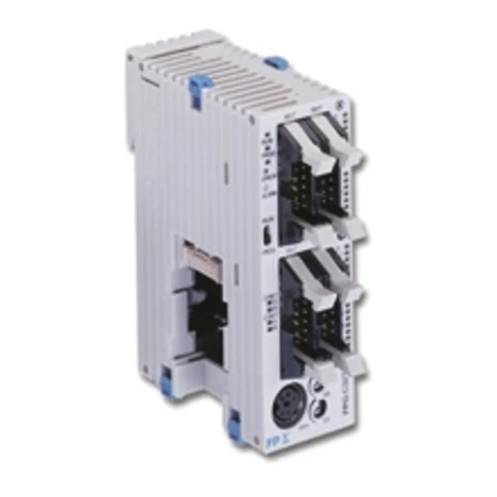
FP∑ Positioning Unit Parts and Specifications 2.1 Parts and Specifications 2.1.1 Parts and Specifications ① Operation status display LEDs These display operation conditions. ② User interface connector for 1 - axis/2 - axis This connector is used to connect a motor driver or external interface. -
Page 28: Operation Status Display Leds
Parts and Specifications FP∑ Positioning Unit 2.1.2 Operation Status Display LEDs LEDs show the same information for each axis. Operation Status Display LEDs Description LED ON LED OFF LED blinks When set to During pulse pulse/sign output During stop ―― Pulse output output method... -
Page 29: Wiring
Chapter 3 Wiring... - Page 30 Wiring FP∑ Positioning UNit...
-
Page 31: Connecting Using Connector For A Discrete-Wire
8 pcs x 1 8 pcs x 2 * 1 connector set and 2 connector sets are supplied with the 2-axis type unit and 4-axis type unit, respectively. Dedicated tool Manufacturer Product number Panasonic Electric Works SUNX Co., Ltd. AXY52000FP... -
Page 32: Assembly Of Discrete-Wire Connector
Wiring FP∑ Positioning UNit 3.1.2 Assembly of Discrete-Wire Connector The wire end can be directly press-fitted without removing the wire’s insulation, saving labor. Procedure: 1. Bend the contact back from the carrier, and set it in the pressure connection tool. 2. -
Page 33: Input /Output Specifications And Out Put Terminal Layout
FP∑ Positioning Unit Wiring 3.2 Input /Output Specifications and Out put terminal Layout 3.2.1 Input /Output Specifications 1-axis type uses the connector pins for only 1-axis type. The signal pins for 2 axes are assigned to a connector. Between the Transistor type and the Line driver type, the pulse output terminal performace is different, but the input terminal and the power supply terminal are in the same specifications. - Page 34 Wiring FP∑ Positioning UNit Output terminals (Line driver output type) Pin number Circuit Signal name Item Description 1 - axis 2 - axis Pulse output A: Line driver (+) Pulse output A: Line driver output Line driver (-) Output format Equivalent to Pulse output B: AM26C31...
- Page 35 FP∑ Positioning Unit Wiring Input Terminals(common) Pin number Circuit Signal name Item Description 1 - axis 2 - axis Operating 21.6V DC to voltage range 26.4V DC Min. ON Home input: 19.2V DC/5.5mA voltage/current 24 V DC (+) Max. OFF (Z24) 2V DC/2mA voltage/current...
- Page 36 Wiring FP∑ Positioning UNit Note: Please use under the specifications for pulse input A, B signal. - 2 phases input method - Direction distinction input method - Individual input method...
-
Page 37: Supplying Power For Internal Circuit Drive
FP∑ Positioning Unit Wiring 3.3 Supplying Power for Internal Circuit Drive Always make sure an external +24V DC power supply is connected to the pins for external input power supply (pin No. A20 and B20). The applied 24V DC passes through an internal DC/DC converter and is converted to 5 V DC voltage. It is then supplied to the various internal circuits as a power supply for internal circuit drive of the pulse command output pin. -
Page 38: Connection Of Pulse Command Output Signal
Wiring FP∑ Positioning UNit 3.4 Connection of Pulse Command Output Signal Two types of output types are available for the FP∑ positioning unit due to two types of the interfaces of motor driver. Select and connect one or the other, depending on the interface of the motor driver being used. -
Page 39: Connection Of Deviation Counter Clear Output Signal (For Servo Motor)
FP∑ Positioning Unit Wiring 3.5 Connection of Deviation Counter Clear Output Signal (for servo motor) This is an example showing connection of the counter clear input to the servo motor driver. An external power supply (+5 V DC to +24 V DC) must be provided for the connection. Note: Always use twisted - pair cables for wiring. -
Page 40: Connection Of Home Input/Near Home Input Signals
Wiring FP∑ Positioning UNit 3.6 Connection of Home Input/Near Home Input Signals This is the home signal input connection for the home return. It should be connected to the Z phase output (Line driver output or Transistor output) of the motor driver, or to an external switch and sensor. -
Page 41: Connection Of Near Home Input Signal
FP∑ Positioning Unit Wiring 3.6.3 Connection of Near Home Input Signal Note: No. B4 and B13 are common for the Near home input, Over limit input(+),Over limit input(-) and Positioning control start input(Timing input). 3.6.4 Connection of Over limit Input Signal Note: No. -
Page 42: Connection Of Pulse Input
Wiring FP∑ Positioning UNit 3.7 Connection of Pulse Input The signal output style may differ depending on Pulser or Encoder. Connect in accordance with the output style. Line driver type, Transistor open collector type and Transistor-resistance pull-up type are available for the output styles. The same pulse input terminal is used for Pulser input operation and Feedback pulse count, so it is used for either. -
Page 43: Precausions On Wiring
FP∑ Positioning Unit Wiring 3.8 Precausions on Wiring Connect the wire in less than or the following length between the Transistor output type and the motor driver, and between the Line driver output type and the motor driver. <Signals applicable> Transistor output Line driver output Deviation counter clear output... - Page 44 Wiring FP∑ Positioning UNit 3-16...
- Page 45 Chapter 4 Confirming the Unit Settings and Design Contents...
- Page 46 Confirming the Unit Settings and Design Contents FP∑ Positioning Unit...
-
Page 47: Confirming The Unit Settings And Design Contents
FP∑ Positioning Unit Confirming the Unit Settings and Design Contents 4.1 Pulse Output Mode 4.1.1 Selection of Rotation Direction Changing this settings allows to rotating a motor in a reverse direction under the same connection status and the driver settings. Shared momory Control code Higher the 8th. -
Page 48: Setting The Shared Memory Control Code Relationship With Rotation Direction
Confirming the Unit Settings and Design Contents FP∑ Positioning Unit 4.1.3 Setting the Shared Memory Control Code Relationship with Rotation Direction Pulse/Sign mode Common memory Control code Higher The 9th. bit The 8th. bit Pulse/Sign mode Common memory Control code Higher The 9th. - Page 49 FP∑ Positioning Unit Confirming the Unit Settings and Design Contents CW/CCW mode Common memory Control code Higher The 9th. bit The 8th. bit CW/CCW mode Common memory Control code Higher The 9th. bit The 8th. bit Note: The direction of rotation varies depending on the wiring, the motor driver settings, the position command value in the program, and other factors.
-
Page 50: Confirming The Slot Number And I/O Number Allocations
Confirming the Unit Settings and Design Contents FP∑ Positioning Unit 4.2 Confirming the Slot Number and I/O Number Allocations 4.2.1 Slot Number Slot Number shows the position of the expansion unit, which is used for a programming. I/O Area allocation varies depending on the Slot Number. 4.2.2 I/O Area Allocation With the positioning unit, as with other I/O units, allocations are entered for the input (X) and output (Y). -
Page 51: Contents Of Input And Output Allocations
FP∑ Positioning Unit Confirming the Unit Settings and Design Contents 4.2.3 Contents of Input and Output Allocations I/O flag number (* 5) 1 - axis 2 - axis type Flag Name Description type 1st axis 1st axis 2nd axis Pulse output busy BUSY ON during pulse output. - Page 52 Confirming the Unit Settings and Design Contents FP∑ Positioning Unit I/O flag number (* 5) 1 - axis Flag Name Description 2 - axis type type 1st axis 1st axis 2nd axis E point When turned ON in the user program, Y100 Y100 Y110...
-
Page 53: Increment And Absolute
FP∑ Positioning Unit Confirming the Unit Settings and Design Contents 4.3 Increment and Absolute There are two ways to set the position command value. Specify whichever due to your usage. 4.3.1 Increment (relative value control) The position command value is normally specified as the relative position from the current position, using a number of pulses. -
Page 54: Absolute (Absolute Value Control)
Confirming the Unit Settings and Design Contents FP∑ Positioning Unit 4.3.2 Absolute (absolute value control) The position command value is normally specified as the absolute position from the home position, using a number of pulses. Example: If the unit is 15,000 pulses away from the home position, it travels +5,000 pulses, “+20000 pulses”... -
Page 55: Selection Of Acceleration / Deceleration Method
FP∑ Positioning Unit Confirming the Unit Settings and Design Contents 4.4 Selection of Acceleration / Deceleration Method 4.4.1 Linear and S Acceleration/Decelerations The FP∑positioning unit has two methods of acceleration and deceleration which can be selected: Linear acceleration/deceleration and S acceleration/deceleration. With linear acceleration/deceleration, acceleration and deceleration (the acceleration from the starting speed to the target speed) are carried out in a straight line. -
Page 56: Indicating The Method Of Acceleration / Deceleration
Confirming the Unit Settings and Design Contents FP∑ Positioning Unit 4.4.3 Indicating the Method of Acceleration / Deceleration Indicating the method of acceleration/deceleration This is specified in the program, as a control code. Example: With E point control The method of control varies depending on the control code. - When the code is H0: increment method, linear acceleration/deceleration - When the code is H1: absolute method, linear acceleration/deceleration - When the code is H2: increment method, S acceleration/deceleration (Sin curve) -
Page 57: Internal Absolute Counter
FP∑ Positioning Unit Confirming the Unit Settings and Design Contents 4.5 Internal Absolute Counter 4.5.1 How the Internal Absolute Counter Works How the internal absolute counter works -The positioning unit is equipped with a function that counts the number of pulses output. -The counted value of each axis is stored in the shared memory area of the positioning unit. - Page 58 Confirming the Unit Settings and Design Contents FP∑ Positioning Unit Countable range of the counter -2,147,483,648 to +2,147,483,647 If the elapsed value exceeds the maximum (or minimum) value, it returns to the minimum (maximum) value. Pulse output does not stop if this occurs, and no error occurs. Shared memory address in which the counter value is stored Address of shared memory (hexadecimal) Description...
-
Page 59: Reading Elapsed Value
FP∑ Positioning Unit Confirming the Unit Settings and Design Contents 4.5.2 Reading Elapsed Value The F150 instruction is used to read the elapsed value from the shared memory of the positioning unit. F150 (READ) instruction This is the instruction used to read data from the memory of the positioning unit. Explanation: “n”... -
Page 60: Writing Elapsed Value
Confirming the Unit Settings and Design Contents FP∑ Positioning Unit 4.5.3 Writing Elapsed Value The F151 instruction is used to write data to the shared memory of the positioning unit. F151 (WRT) instruction This is the instruction that write data to the shared memory of the positioning unit. Explanation: This stores the contents of the CPU area specified by “S2”... -
Page 61: Power On And Off, And Booting The System
Chapter 5 Power ON and OFF, and Booting the System... - Page 62 Turning the Power ON and OFF, and Booting the System FP2 positioning Unit...
-
Page 63: Safety Circuit Design
FP2 positioning Unit Turning the Power ON and OFF, and Booting the System Turning the 5.1 Safety Circuit Design Example of a safety circuit Installation of the Over limit switch Safety circuit based on Positioning unit Install Over limit switches as shown above. Connect them to Over limit input(+) and Over limit input (-) of the Positioning unit. -
Page 64: Before Turning On The Power
Turning the Power ON and OFF, and Booting the System FP2 positioning Unit 5.2 Before Turning ON the Power Items to check before turning ON the power System configuration example ① Checking connections to the various devices Check to make sure the various devices have been connected as indicated by the design. ②... -
Page 65: Procedure For Turning On The Power
FP2 positioning Unit Turning the Power ON and OFF, and Booting the System Turning the 5.3 Procedure for Turning ON the Power When turning ON the power to the system incorporating the positioning unit, the nature and statuses of any external devices connected to the system should be taken into consideration, and sufficient care should be taken that turning ON the power does not initiate unexpected movements or operations. -
Page 66: Procedure For Turning Off The Power
Turning the Power ON and OFF, and Booting the System FP2 positioning Unit 5.3.2 Procedure for Turning OFF the Power Procedure: 1. Check to make sure the rotation of the motor has stopped, and then turn OFF the power supply for the motor driver. -
Page 67: Confirming While The Power Is On
FP2 positioning Unit Turning the Power ON and OFF, and Booting the System Turning the 5.4 Confirming while the Power is ON Items to check when the power is ON System configuration example Checking should be carried out in the four general stages described below. 5.4.1 Checking the External Safety Circuit Check the safety circuit recommended by the manufacturer of the motor to confirm the power supply cutoff of the motor driver and other functions by turnning ON the CW/CCW driving inhibition switch of an... -
Page 68: Checking The Safety Circuit Based On Positioning Unit
Turning the Power ON and OFF, and Booting the System FP2 positioning Unit 5.4.2 Checking the Safety Circuit based on Positioning Unit Procedure: 1. Using forced operation of Over limit switch for the external safety circuit of the positioning unit, check to see if the Over limit input is being properly taken into the positioning unit. -
Page 69: Checking The Operation Of The Near Home Switch And Home Switch
FP2 positioning Unit Turning the Power ON and OFF, and Booting the System Turning the 5.4.4 Checking the Operation of the Near Home Switch and Home Switch Procedure: 1. Using forced operation of the home input and near home input, check to make sure the operation display LEDs on the positioning unit light. - Page 70 Turning the Power ON and OFF, and Booting the System FP2 positioning Unit 5-10...
-
Page 71: E Point Control: Single - Speed Acceleration / Deceleration
Chapter 6 E Point Control: Single - Speed Acceleration / Deceleration... -
Page 72: Sample Program
Automatic Acceleration / Deceleration Control (E Point Control: Single - Speed Acceleration / Deceleration) FP∑ Positioning Unit 6.1 Sample Program 6.1.1 Increment (Relative Value Control): Plus (+) Direction For this control, the “Increment” method of travel amount setting is used, and the direction in which the elapsed value increases as the motor rotates is set as the plus (+) direction. - Page 73 FP∑ Positioning Unit Automatic Acceleration / Deceleration Control (E Point Control: Single - Speed Acceleration / Deceleration) Shared memory settings Set values in sample Control parameter setting content Range of acceptable settings program example H80 Note: <Increment method, Linear Refert to page 16-7. Control code acceleration/deceleration>...
-
Page 74: Increment (Relative Value Control): Minus ( - ) Direction
Automatic Acceleration / Deceleration Control (E Point Control: Single - Speed Acceleration / Deceleration) FP∑ Positioning Unit 6.1.2 Increment (Relative Value Control): Minus ( - ) Direction For this control, the “Increment” method of travel amount setting is used, and the direction in which the elapsed value increases as the motor rotates is set as the plus (+) direction. - Page 75 FP∑ Positioning Unit Automatic Acceleration / Deceleration Control (E Point Control: Single - Speed Acceleration / Deceleration) Shared memory settings Set values in sample Control parameter setting content Range of acceptable settings program example H80 Note: <Increment method, Linear Refer to page 16-7. Control code acceleration/deceleration>...
-
Page 76: Absolute (Absolute Value Control)
Automatic Acceleration / Deceleration Control (E Point Control: Single - Speed Acceleration / Deceleration) FP∑ Positioning Unit 6.1.3 Absolute (Absolute Value Control) For this control, the “Absolute” method of travel amount setting is used, and the direction in which the elapsed value increases as the motor rotates is set as the plus (+) direction. - Page 77 FP∑ Positioning Unit Automatic Acceleration / Deceleration Control (E Point Control: Single - Speed Acceleration / Deceleration) Shared memory settings Set values in sample Control parameter setting content Range of acceptable settings program example H81 Note: <Absolute method, Linear Refer to page 16-7. Control code acceleration/deceleration>...
-
Page 78: Flow Of E Point Control Operation
Automatic Acceleration / Deceleration Control (E Point Control: Single - Speed Acceleration / Deceleration) FP∑ Positioning Unit 6.2 Flow of E Point Control Operation E point control: Single - speed acceleration/deceleration When the E point control startup relay (EST) is turned ON, acceleration/deceleration control is carried out automatically at a single speed, in accordance with the specified data table. - Page 79 FP∑ Positioning Unit Automatic Acceleration / Deceleration Control (E Point Control: Single - Speed Acceleration / Deceleration) Operation steps Step 1: Preparatory stage The data required for operation is transferred to the shared memory in advance. Step 2: Executing the operations Operation begins when the flag Y100 for E point control is turned ON.
-
Page 80: Operation Of The Input And Output Before And After E Point Control
Automatic Acceleration / Deceleration Control (E Point Control: Single - Speed Acceleration / Deceleration) FP∑ Positioning Unit 6.3 Operation of the Input and Output Before and After E Point Control E point control start flag(Y_0) 1. E point control is initiated based on the parameters written to the positioning unit. 2. -
Page 81: Operation At Over Limit Input
FP∑ Positioning Unit Automatic Acceleration / Deceleration Control (E Point Control: Single - Speed Acceleration / Deceleration) 6.4 Operation at Over limit Input E point control operation is as follows when Over limit input(+) and Over limit input(-) is ON. Condition Direction Limit status... - Page 82 Automatic Acceleration / Deceleration Control (E Point Control: Single - Speed Acceleration / Deceleration) FP∑ Positioning Unit 6-12...
-
Page 83: P Point Control: Multi - Stage Acceleration / Deceleration7-1
Chapter 7 P Point Control: Multi - Stage Acceleration / Deceleration... -
Page 84: Sample Program
FP∑ Positioning Unit P Point Control: Multi - Stage Acceleration / Deceleration 7.1 Sample Program 7.1.1 Increment (Relative Value Control): Plus (+) Direction For this control, the “Increment” method of travel amount setting is used, and the direction in which the elapsed value increases as the motor rotates is set as the plus (+) direction. - Page 85 FP∑ Positioning Unit P Point Control: Multi - Stage Acceleration / Deceleration Shared memory settings Control parameter Set values in sample program example Range of acceptable settings setting content 1st speed 2nd speed 3rd speed H80 Note: Increment The same The same method, Control code...
-
Page 86: Increment (Relative Value Control): Minus ( - ) Direction
FP∑ Positioning Unit P Point Control: Multi - Stage Acceleration / Deceleration 7.1.2 Increment (Relative Value Control): Minus ( - ) Direction For this control, the “Increment” method of travel amount setting is used, and the direction in which the elapsed value increases as the motor rotates is set as the plus (+) direction. - Page 87 FP∑ Positioning Unit P Point Control: Multi - Stage Acceleration / Deceleration Shared memory settings Control parameter Set values in sample program example Range of acceptable settings 1st speed 2nd speed 3rd speed setting content H80 Note: Increment method, The same The same Refer to page 16-7.
-
Page 88: Absolute (Absolute Value Control)
FP∑ Positioning Unit P Point Control: Multi - Stage Acceleration / Deceleration 7.1.3 Absolute (Absolute Value Control) For this control, the “Absolute” method of travel amount setting is used, and the direction in which the elapsed value increases as the motor rotates is set as the plus (+) direction. Pulse output diagram... - Page 89 FP∑ Positioning Unit P Point Control: Multi - Stage Acceleration / Deceleration Shared memory settings Control parameter setting Set values in sample program example Range of acceptable settings 1st speed 2nd speed 3rd speed content H81 Note: Absolute method, The same The same Refer to page 16-7.
-
Page 90: Flow Of P Point Control Operation
FP∑ Positioning Unit P Point Control: Multi - Stage Acceleration / Deceleration 7.2 Flow of P Point Control Operation P point control: Multi - stage acceleration/deceleration -When the flag for initiating P point control (Y_1) is turned ON, acceleration/deceleration control is carried out repeatedly, in accordance with the specified data table, and then the operation stops. - Page 91 FP∑ Positioning Unit P Point Control: Multi - Stage Acceleration / Deceleration Data necessary for settings As shown below, data items must be written to the specified addresses in the shared memory, in the order in which operations are to be executed. In the illustration below, the operations and processing of the P point control consists of sections I to III are explained.
- Page 92 FP∑ Positioning Unit P Point Control: Multi - Stage Acceleration / Deceleration Operation steps Step 1: Preparatory stage The data required for section I of the operation is transferred to the shared memory in advance. Step 2: Executing the operation of Section I Operation begins when the flag Y101 for P point control start is turned ON.
- Page 93 FP∑ Positioning Unit P Point Control: Multi - Stage Acceleration / Deceleration Step 3: Executing the operation of Section II When the operation of section I is completed, operation shifts to section II. (At this point, X10A goes ON. When X10A goes ON, the data for the operation of section III is transferred to the shared memory.
-
Page 94: Operation Of The Input And Output Flag Before And After P Point Control
FP∑ Positioning Unit P Point Control: Multi - Stage Acceleration / Deceleration 7.3 Operation of the Input and Output Flag Before and After P Point Control P point control start flag (Y_1) 1. P point control is initiated based on the parameters written to the positioning unit. 2. -
Page 95: Precautions When Creating P Point Control Programs
FP∑ Positioning Unit P Point Control: Multi - Stage Acceleration / Deceleration 7.4 Precautions When Creating P Point Control Programs 7.4.1 Precautions Concerning the Set Value Change Confirmation Flag X_A The set value change confirmation flag is turned ON and OFF at the timing noted below, so an interlock should be applied to prevent the shared memory or other data from being overwritten at the same timing. - Page 96 FP∑ Positioning Unit P Point Control: Multi - Stage Acceleration / Deceleration If the P point control program is booted Because an interlock is in effect, the E while the E point control program has been point control program cannot be booted if booted and is running, the flag X10A changes, the P point control program has already resulting in affecting the P point control...
-
Page 97: Operation At Over Limit Input
FP∑ Positioning Unit P Point Control: Multi - Stage Acceleration / Deceleration 7.5 Operation at Over limit Input P point control operation is as follows when Over limit input (+) or Over limit input (-) is ON. Condition Direction Limit status Operation Table not to move, Over limit input (+):ON... - Page 98 FP∑ Positioning Unit P Point Control: Multi - Stage Acceleration / Deceleration 7-16...
- Page 99 Chapter 8 JOG Operation...
- Page 100 JOG Operation FP∑ Positionig Unit 8.1 Sample Program 8.1.1 JOG Operation (Forward and Reverse) This is the basic program for forward and reverse rotation using the external switch. The direction in which the elapsed value increases as the motor rotates is set as the plus (+) direction. -Pulses are output as long as the startup flag is ON in the manual mode.
-
Page 101: Jog Operation
FP∑ Positinoning Unit JOG Operation Shared memory settings Control parameter Set values in sample program Range of acceptable settings setting content example H80 Note: Linear Refer to page 16-7 Control code acceleration/deceleration K500 K0 to K4,000,000 Startup speed (pps) K1 to K4,000,000 K10000 Specify a value larger than the Target speed (pps) -
Page 102: Jog Operation (Forward, Reverse And Speed Changes)
JOG Operation FP∑ Positionig Unit 8.1.2 JOG Operation (Forward, Reverse and Speed Changes) This is the basic program for forward and reverse rotation using the external switch. The direction in which the elapsed value increases as the motor rotates is set as the plus (+) direction -Pulses are output as long as the startup flag is ON in the manual mode. - Page 103 FP∑ Positinoning Unit JOG Operation Shared memory settings Set values in sample program example Control parameter Range of acceptable settings Low – speed High – speed setting content settings settings H80 Note: Refer to page 16-7 Control code Linear acceleration/deceleration K500 K0 to K4,000,000 Startup speed (pps)
-
Page 104: Sequence Flow For Jog Operation
JOG Operation FP∑ Positionig Unit 8.2 Sequence Flow for JOG Operation JOG operation When is mounted in slot 0 Operation example When the flag for forward rotation (Y103) (JGF) is turned ON, forward rotation begins and acceleration is initiated based on the settings. When the flag is turned OFF, deceleration takes place based on the settings, and the operation stops. - Page 105 FP∑ Positinoning Unit JOG Operation Operation steps Step 1: Preparatory stage The data for operation is transferred to the shared memory ahead of time. Step 2: Executing the operations Forward The start flag Y103 for forward rotation is turned ON. Reverse The start flag Y104 for reverse rotation is turned ON.
-
Page 106: Changing The Speed During Jog Operation
JOG Operation FP∑ Positionig Unit 8.3 Changing the Speed During JOG Operation Specifying a speed change during JOG operation To change the speed during JOG operation, the program should be set up so that only the “Target speed” parameter in the shared memory is overwritten after JOG operation has begun. Pulse output diagram Note: The target speed change during JOG operation is available only for Linear acceleration/deceleration. - Page 107 FP∑ Positinoning Unit JOG Operation Sample Program Acceleration/deceleration time when the speed is changed -If the JOG speed is changed during JOG operation, it is not possible to specify the acceleration/deceleration time when the speed changes. -The acceleration/deceleration time is determined by the “Rate of acceleration”, which is the speed change from the startup speed to the point where the first target speed is reached, and the acceleration/deceleration time continues to change until this “Rate of acceleration”...
-
Page 108: Teaching Following Jog Operation
JOG Operation FP∑ Positionig Unit 8.4 Teaching Following JOG Operation 8.4.1 Example of Teaching Settings, and Sample Program Example of teaching operation following JOG operation -The current position can be determined by reading the counter value stored in the shared memory of the unit after JOG operation has taken place. - Page 109 FP∑ Positinoning Unit JOG Operation Sample Program Precautions concerning the program When Over limit switch (+) and Over limit switch(-) are not connected, change the limit input valid logic using the control code. The default setting is the input existing when the power is not supplied, that is, is the input existing without the Over limit switch connection.
-
Page 110: Action Of The I/O Flag Before And After Jog Operation
JOG Operation FP∑ Positionig Unit 8.5 Action of the I/O Flag Before and After JOG Operation Forward JOG flag (Y_3)/Reverse JOG flag (Y_4) 1. JOG operation is initiated based on the parameters written to the positioning unit. 2. The operation is not initiated during the time that the pulse output busy flag (X_0) is ON. (it has already been initiated). -
Page 111: Operation At Over Limit Input
FP∑ Positinoning Unit JOG Operation 8.6 Operation at Over limit Input JOG operation is as follows when Over limit input (+) and Over limit input (-) is ON . The operation is possible for the direction in opposite of the input limit. Condition Direction Limit status... -
Page 112: Cautions On An Over Limit Switch
JOG Operation FP∑ Positionig Unit 8.7 Cautions on an Over Limit Switch A over limit input valid for a Jog operation, Home return (including Home search) and Pulser input is the one logically found in the direction of the table movement. i.e. if an Over limit switch (-) is input for a movement in (+) direction or an Over limit switch (+) is input for a movement in (-) direction, the table will not stop. -
Page 113: Jog Positioning Operation
Chapter 9 JOG Positioning Operation... - Page 114 JOG Positioning Operation FP∑ Positioning Unit...
-
Page 115: Sample Program
FP∑ Positioning Unit JOG Positioning Operation 9.1 Sample Program 9.1.1 Increment (Relative Value Control): Plus (+) Direction This is a program to start the JOG positioning operation (speed control -> position control) from JOG operation by the external switch input. The “Increment”... - Page 116 JOG Positioning Operation FP∑ Positioning Unit Pulse output diagram Operations of the various flag -X100, the Pulse output busy (BUSY) flag, is turned ON during the JOG positioning operation and is turned OFF when the pulse output is completed. -X101, the Pulse output done (EDP) flag, is turned ON when the pulse output is completed and remains until any of E point control, P point control, JOG operation, JOG positioning operation, home return or pulser input enabled operations is started up.
- Page 117 FP∑ Positioning Unit JOG Positioning Operation Shared memory settings Control parameter Set values in sample Range of acceptable settings setting content program example H80 Note 1: <Increment method, Linear Refer to page 16-7. Control code acceleration/deceleration> K500 K0 to K4,000,000 Startup speed (pps) K1 to K4,000,000 K10000...
- Page 118 JOG Positioning Operation FP∑ Positioning Unit Precautions concerning the program When Over limit switch (+) and Over limit switch (-) are not connected, change the limit input valid logic using the control code. The default setting is the input existing when the power is not supplied, that is, is the input existing without the Over limit switch connection.
-
Page 119: Increment (Relative Value Control): Minus ( - ) Direction
FP∑ Positioning Unit JOG Positioning Operation 9.1.2 Increment (Relative Value Control): Minus ( - ) Direction This is a program to start the JOG positioning operation (speed control -> position control) from JOG operation by the external switch input. The “Increment” method is used for the travel amount setting and the direction in which the elapsed value increases as the motor rotates is set as the plus (+) direction. - Page 120 JOG Positioning Operation FP∑ Positioning Unit Pulse output diagram Operations of the various flag -X100, the Pulse output busy (BUSY) flag, is turned ON during the JOG positioning operation and is turned OFF when the pulse output is completed. -X101, the Pulse output done (EDP) flag, is turned ON when the pulse output is completed and remains until any of E point control, P point control, JOG operation, JOG positioning operation, home return or pulser input enabled operations is started up.
- Page 121 FP∑ Positioning Unit JOG Positioning Operation Shared memory settings Control parameter Set values in sample program Range of acceptable settings setting content example H80 Note 1: Increment method, Linear Refer to page 16-7. Control code acceleration/deceleration K500 K0 to K4,000,000 Startup speed (pps) K1 to K4,000,000 K10000...
- Page 122 JOG Positioning Operation FP∑ Positioning Unit Precautions concerning the program When Over limit switch (+) and Over limit switch (-) are not connected, change the limit input valid logic using the control code. The default setting is the input existing when the power is not supplied, that is, is the input existing without the Over limit switch connection.
-
Page 123: Flow Of Jog Positioning
FP∑ Positioning Unit JOG Positioning Operation 9.2 Flow of JOG Positioning JOG positioning operation -When the flag for JOG positioning operation start flag (JGST) (Y_8) is turned ON, a speed control, automatic acceleration/deceleration, in accordance with the specified data table, and the table travels for the value set by the positioning control start input. - Page 124 JOG Positioning Operation FP∑ Positioning Unit When Y108 is set to ON in the program, the motor of the first axis begins accelerating. X100 is a Pulse output busy (BUSY) flag that indicates that operation is in progress, while X101 is a Pulse output done (EDP) flag that indicates that operation has been completed.
- Page 125 FP∑ Positioning Unit JOG Positioning Operation Operation steps Step 1: Preparatory stage The data required for operation is transferred to the shared memory in advance. Data for JOG positioning operation Step 2: Executing the operations Operation begins when the flag Y108 for JOG positioning operation is turned ON. The control code determines whether S acceleration/deceleration or linear acceleration/deceleration is used.
-
Page 126: Operation Of The Input And Output Flag At Jog Positioning Operation
JOG Positioning Operation FP∑ Positioning Unit 9.3 Operation of the Input and Output Flag at JOG Positioning Operation JOG positioning operation start flag(Y_8) 1. JOG positioning operation is initiated based on the parameters written to the positioning unit. 2. JOG positioning operation is not initiated during the time that the pulse output busy flag (X_0) is ON. (already initiated.)... -
Page 127: Operation At Over Limit Input
FP∑ Positioning Unit JOG Positioning Operation 9.4 Operation at Over limit Input JOG positioning operation is as follows when Over limit input (+) or Over limit input(-) is ON. The operation is possible for the direction in opposite of the input limit. Condition Direction Limit status... -
Page 128: Special Mention
JOG Positioning Operation FP∑ Positioning Unit 9.5 Special Mention Positioning control start input (Timing input) and where to stop The FP∑ Positioning unit performs the process in the very high speed, so that it starts counting the number of the output pulses within 15µs from when the positioning control start input (timing input) is ON during the JOG positioning operation. -
Page 129: Home Return
Chapter 10 Home Return... - Page 130 Home Return FP2 Positioning Unit 10-2...
-
Page 131: How To Use Home Return
FP2 Positioning Unit Home Return 10.1 How to Use Home Return 10.1.1 Return to Home Position by a Home Search Home Search Over limit switch(+) or Over limit switch(-) when the home position is in between where the table travels or when the direction of the home return could be in the both directions, so that the Home return in the both directions will be possible. - Page 132 Home Return FP2 Positioning Unit 3) When the near home is detected again, the speed slows down from the target speed to the startup speed and the table stops at the home position. -When Near home input is ON during home return 1) Home return operation starts in the opposite direction of the one specified in the program.
-
Page 133: Home Return (Home Search Invalid Mode)
FP2 Positioning Unit Home Return 10.1.2 Home Return (Home search invalid mode) Home search invalid mode When the home position is in between where the table travels, the table does not reverse the direction but stops by detecting Over limit switch (+) or (-). Setting the control code Lower the 6th. -
Page 134: Sample Program
Home Return FP2 Positioning Unit 10.2 Sample Program 10.2.1 Search to home in the Minus Direction Search to the home position are carried out in the minus direction. The direction in which the elapsed value increases as the motor rotates is set as the plus (+) direction. The home input is connected to the Z phase output of the motor driver, or to an external switch or a sensor. - Page 135 FP2 Positioning Unit Home Return Shared memory settings Control parameter Set values in sample program Range of acceptable settings setting content example HD0 Note: The specified values vary Acceleration/deceleration method: depending on the method of Linear acceleration/deceleration acceleration/deceleration, the home Direction of home return: Control code return direction, the home input...
-
Page 136: Search To The Home In The Plus Direction
Home Return FP2 Positioning Unit 10.2.2 Search to the home in the Plus Direction Search to the home position is carried out in the plus direction. The direction in which the elapsed value increases as the motor rotates is set as the plus (+) direction. The home input is connected to the Z phase output of the motor driver, or to an external switch or sensor. - Page 137 FP2 Positioning Unit Home Return Shared memory settings Control parameter Set values in sample program Range of acceptable settings setting content example HD4 Note: Acceleration/deceleration method: The specified values vary Linear acceleration depending on the method of /deceleration acceleration/deceleration, the Control code Direction of home return: home return direction, the home...
-
Page 138: Home Return In The Minus Direction (Home Search Invalid Mode)
Home Return FP2 Positioning Unit 10.2.3 Home Return in the Minus Direction (Home search invalid mode) Returns to the home position are carried out in the minus direction. The direction in which the elapsed value increases as the motor rotates is set as the plus (+) direction. The home input is connected to the Z phase output of the motor driver, or to an external switch or sensor. - Page 139 FP2 Positioning Unit Home Return Shared memory settings Control parameter Set values in sample program Range of acceptable settings setting content example H90 Note: Acceleration/deceleration method: Linear The specified values vary acceleration/ deceleration depending on the method of Direction of home return: acceleration/deceleration, the Control code - direction of elapsed value...
-
Page 140: Home Return In The Plus Direction (Home Search Invalid Mode)
Home Return FP2 Positioning Unit 10.2.4 Home Return in the Plus Direction (Home search invalid mode) Returns to the home position are carried out in the plus direction. The diretion in which the elapsed value increases as the motor rotates is set as the plus (+) direction. The home input is connected to the Z phase output of the motor driver, or to an external switch or sensor. - Page 141 FP2 Positioning Unit Home Return Shared memory settings Control parameter Set values in sample program Range of acceptable settings setting content example H94 Note: Acceleration/deceleration method: The specified values vary depending Linear acceleration/ on the method of deceleration acceleration/deceleration, the home Control code Direction of home return: return direction, the home input...
-
Page 142: Flow Of Operation Following A Home Return
Home Return FP2 Positioning Unit 10.3 Flow of Operation Following a Home Return Home return When is mounted in slot 0 Operation example When the startup flag is turned ON, acceleration is carried out based on the settings, until the target speed is reached. - Page 143 FP2 Positioning Unit Home Return Step 2: Executing the operations The startup flag Y102 is turned ON. The control code determines whether S acceleration/deceleration or linear acceleration/deceleration is used. When the startup flag is turned ON, acceleration takes places for the acceleration/deceleration time it takes to reach the target speed, and the table moves.
-
Page 144: Operation If The Home Input Is The Z Phase Of The Servo Driver
Home Return FP2 Positioning Unit 10.3.1 Operation If the Home Input is the Z Phase of the Servo Driver When near home input is input, the speed slows, and when the starup speed has been reached, the positioning unit recognizes the first input Z phase signal as the home input signal, and stops. When is mounted in slot 0 Note: Z phase signals input during deceleration are not viewed as home input signals. -
Page 145: Operation If The Home Input Is Through An External Switch
FP2 Positioning Unit Home Return 10.3.2 Operation If the Home Input is Through an External Switch When near home input is input, the speed slows. When the startup speed has been reached, the home input signal is input and stops. When is mounted in slot 0 Note: Home input signals input during deceleration are not viewed as home input signals. -
Page 146: Action Of The I/O Flag Before And After A Home Return Operation
Home Return FP2 Positioning Unit 10.4 Action of the I/O Flag Before and After a Home Return Operation 10-18... - Page 147 FP2 Positioning Unit Home Return Home return start flag (Y_2) 1. Home return is initiated based on the parameters written to the positioning unit. 2. The flag is not initiated during the time that the pulse output busy flag (X_0) is ON. (It has already been initiated).
-
Page 148: Checking The Home And Near Home Input Logic
Home Return FP2 Positioning Unit 10.5 Checking the Home and Near Home Input Logic 10.5.1 When “Input Valid When Power is Supplied” is Specified In cases like that below, when power is supplied to the input circuit of the unit, the “Power supplied” control code for the program is selected from the control code table. -
Page 149: Practical Use For A Home Return
FP2 Positioning Unit Home Return 10.6 Practical Use for a Home Return 10.6.1 When One Switch is Used as the Home Input Example of usage method - Connection Only the home input switch is installed and connected. (No near home input switch is connected.) - Input logic settings The control code in the shared memory should be set as indicated below. -
Page 150: When One Switch On And Off Are Assigned To Near Home Input And Home
Home Return FP2 Positioning Unit 10.6.2 When One Switch ON and OFF are assigned to Near Home Input and Home Environment available for this The system in which the near home input switch is once turned ON and then OFF when the home return is started. - Page 151 FP2 Positioning Unit Home Return -Operation When a home return begins, the motor rotates in the direction of the home return. When the near home input switch is turned ON, the speed slows down to the startup speed. The motor rotates the further and the near home input will be OFF. At this point, the home input should already be ON, as a result of the input logic, and the motor stops.
-
Page 152: Operation At Over Limit Input
Home Return FP2 Positioning Unit 10.7 Operation at Over limit Input Home return operation is as follows when Over limit input (+) or Over limit input (-) is ON. The operation in the direction in opposite to the input limit is possible. Home Return (without home search) Condition Direction... -
Page 153: Cautions On An Over Limit Switch
FP2 Positioning Unit Home Return 10.8 Cautions on an Over Limit Switch A Over limit input valid for a Jog operation, Home return (including Home search) and Pulser input is the one logically found in the direction of the table movement. i.e. if an Over limit switch (-) is input for a movement in (+) direction or an Over limit switch (+) is input for a movement in (-) direction, the table will not stop. -
Page 154: Special Mention
Home Return FP2 Positioning Unit 10.9 Special Mention The time from the home input to the pulse output stop during the home return (home search) The FP∑Positioning unit performs the process in the very high speed, so that it starts counting the number of the output pulses within 1µs from when the home input is ON. -
Page 155: Pulser Input Operation
Chapter 11 Pulser Input Operation... -
Page 156: Sample Program
Pulser Input Operation FP∑ Positioning Unit 11.1 Sample Program 11.1.1 Pulser input operation (Transfer multiple: 1 multiple setting) The rotation direction of the motor in which the elapsed value increases is set as the plus direction, and “pulse/sign” is set as the pulse output mode. The normal setting system Pulse output diagram 11-2... - Page 157 FP∑ Positioning Unit Pulser Input Operation Shared memory settings Control parameter Set values in sample Range of acceptable settings setting content program example H80 Note: Refer to page 16-7. Control code Multiplication ratio:×1 multiple K1000 K1 to K4,000,000 Target speed (pps) Note: If the Over limit input error occurs, set H0 as the limit input valid logic can be changed.
-
Page 158: Pulser Input Operation (Transfer Multiple: 5 Multiple Setting)
Pulser Input Operation FP∑ Positioning Unit 11.1.2 Pulser input operation (Transfer multiple: 5 multiple setting) The rotation direction of the motor in which the elapsed value increases is set as the plus direction, and “pulse/sign” is set as the pulse output mode. The normal setting system Pulse output diagram 11-4... - Page 159 FP∑ Positioning Unit Pulser Input Operation Shared memory settings Control parameter Set values in sample program Range of acceptable settings setting content example H280 Note: Refer to page 16-7. Control code Multiplication ratio:×5 multiple K10000 K1 to K4,000,000 Target speed (pps) Note: If the limit error occurs, set H200 as the limit input valid logic can be changed.
-
Page 160: Sequence Flow For Pulser Input Operation
Pulser Input Operation FP∑ Positioning Unit 11.2 Sequence Flow for Pulser input operation Pulser input operation -A pulse generator (pulser) can be connected, and the motor can be controlled in the manual mode. Pulser signals can be input while the pulser input enabled flag (PEN) is ON. -The user can select the number of pulses to be sent to the motor driver in relation to one pulser signal pulse (by setting the control code in the shared memory). - Page 161 FP∑ Positioning Unit Pulser Input Operation Operation steps Step 1: Preparatory stage The data required for operation is transferred to the shared memory in advance. Step 2: Executing the operations The input enabled flag Y107 is turned ON. This sets the system in standby mode for input from the pulser. Forward rotation The pulser rotates in the forward direction.
- Page 162 Pulser Input Operation FP∑ Positioning Unit Reference: Value of the internal absolute counter during pulser input operation The internal absolute counter counts the number of pulses output. Consequently, in the instant that pulses are being input, the number of pulses input from the pulser does not equal to the value counted by the counter.
-
Page 163: Action Of The I/O Flag During Pulser Input Operation
FP∑ Positioning Unit Pulser Input Operation 11.3 Action of the I/O Flag During Pulser Input Operation Pulser input enabled flag (Y_7) 1. This is in pulser input operation status, based on the parameters written to the positioning unit. 2. This does not shift to enabled status while the pulse output busy flag X_0 is ON. 3. -
Page 164: Operation At Over Limit Input
Pulser Input Operation FP∑ Positioning Unit 11.4 Operation at Over limit Input Pulser input operation is as follows when Over limit inout (+) or Over limit input(-) is ON. The operation is possible for the direction in opposite of the input limit. Condition Direction Limit status... -
Page 165: Cautions On An Over Limit Switch
FP∑ Positioning Unit Pulser Input Operation 11.5 Cautions on an Over Limit Switch A over limit input valid for a Jog operation, Home return (including Home search) and Pulser input is the one logically found in the direction of the table movement. i.e. if an Over limit switch (-) is input for a movement in (+) direction or an Over limit switch (+) is input for a movement in (-) direction, the table will not stop. -
Page 166: Types Of Manual Pulse Generators That Can Be Used
Pulser Input Operation FP∑ Positioning Unit 11.6 Types of Manual Pulse Generators That Can be Used A pulse generators should be used for which the number of output pulses is “25P/R” (25 pulses per cycle). With the “100P/R” (100 pulses per cycle) type, four pulses are output per click, and operation may not be accurate in some cases. -
Page 167: Deceleration Stop And Forced Stop
Chapter 12 Deceleration Stop and Forced Stop... - Page 168 Deceleration Stop and Forced Stop FP2 Positioning Unit 12-2...
-
Page 169: Sample Program
FP2 Positioning Unit Deceleration Stop and Forced Stop 12.1 Sample Program 12.1.1 In - progress Stopping, Emergency Stopping Program Precautions concerning the program -The number of the stop input flag varies depending on the number of axes that the unit has, and the position in which it is mounted. - Page 170 Deceleration Stop and Forced Stop FP2 Positioning Unit Pulse output diagram Deceleration stop operation (In - progress stop) Forced stop operation (Emergency stop) 12-4...
-
Page 171: Operations For A Deceleration Stop And Forced Stop
FP2 Positioning Unit Deceleration Stop and Forced Stop 12.2 Operations for a Deceleration Stop and Forced Stop 12.2.1 Deceleration Stop If the deceleration stop flag is turned ON during operation, the operation is interrupted, and the speed slows. When the startup speed is reached, pulse output stops. This operation is common to E point control, P point control, home return, JOG operation and JOG positioning operation. -
Page 172: I/O Flag Operation Before And After A Stop
Deceleration Stop and Forced Stop FP2 Positioning Unit 12.3 I/O Flag Operation Before and After a Stop Deceleration stop flag (Y_6) 1. When the deceleration stop flag goes ON, the operation in progress is interrupted, and deceleration begins. 2. After deceleration has begun and the speed has slowed to the startup speed, pulse output stops. 3. -
Page 173: Precautions Concerning Stopping Operations
FP2 Positioning Unit Deceleration Stop and Forced Stop 12.4 Precautions Concerning Stopping Operations 12.4.1 Pulse Output Done Flag Status After a Stop For either a deceleration stop or a forced stop, the pulse output done flag goes ON after operation has stopped. - Page 174 Deceleration Stop and Forced Stop FP2 Positioning Unit 12-8...
-
Page 175: Feedback Counter
Chapter 13 Feedback Counter... - Page 176 Feedback Counter FP2 Positioning Unit 13-2...
-
Page 177: Sample Program
FP2 Positioning Unit Feedback Counter 13.1 Sample Program 13.1.1 Detecting Power Swing by Comparing Feedback Count with Elapsed Value For this control, the “Increment” method of travel amount setting is used, and the direction in which the elapsed value increases as the motor rotates is set as the plus (+) direction. 13-3... - Page 178 Feedback Counter FP2 Positioning Unit Pulse output diagram Operations of the various flags -Pulse output busy flag (X100) goes ON when E point control is started and goes OFF when the pulse output is completed. -Pulse output done flag (X101) goes ON when the pulse output is completed. This remains ON until the next operation of either E point control, P point control, JOG operation, JOG positioning operation, home return or pulser input operations is started.
- Page 179 FP2 Positioning Unit Feedback Counter Program The following example program compares the count of the output pulses with the count of the feedback pulses at the E point control and makes the deceleration stop if the count is out of the allowable range. For the pulse count of the feedback counter, read the values in H10F, H10E for the 1st.
-
Page 180: Feedback Counter Functions
Feedback Counter FP2 Positioning Unit 13.2 Feedback Counter Functions -The feedback counter can be used as a general-purpose counter as 2-phase input, Direction distinction input or Individual input. - The feedback counter uses the contact which is the same as the one for the pulse input signal. Accordingly, it can not function together with the pulser input operation. -
Page 181: Feedback Counter Input Method
FP2 Positioning Unit Feedback Counter 13.3 Feedback Counter Input Method 2-phase input <normal settings> Control code Higher side H0 2-phase input <reverse settings> Control code Higher side H1 Direction distinction input <normal settings> Control code Higher side H4 Direction distinction input <reverse settings> Control code Higher side H5 13-7... - Page 182 Feedback Counter FP2 Positioning Unit Individual input <normal settings> Control code Higher side H8 Individual input <reverse settings> Control code Higher side H9 13-8...
-
Page 183: Feedback Counter Transfer Multiple Function
FP2 Positioning Unit Feedback Counter 13.4 Feedback Counter Transfer Multiple Function 2-phase input: 1 transfer multiple 2-phase input: 2 transfer multiple 2-phase input: 4 transfer multiple 13-9... - Page 184 Feedback Counter FP2 Positioning Unit Direction distinction input: 1 transfer multiple Direction distinction input: 2 transfer multiple Individual input: 1 transfer multiple Individual input: 2 transfer multiple 13-10...
-
Page 185: Precautions Concerning The Operation And Programs
Chapter 14 Precautions Concerning the operation and Programs... - Page 186 Precautions Concerning the Operation and Programs FP∑ Positioning Unit 14-2...
-
Page 187: Precautions Relating To Basic Operations Of The Unit
FP∑ Positioning Unit Precautions Concerning the Operation and Programs 14.1 Precautions Relating to Basic Operations of the Unit 14.1.1 Values of Shared Memory are Cleared When Power is Turned OFF The data in the shared memory of the positioning unit is not backed up if a power failure occurs. As a result, when the power supply is turned ON again, the default operation data should be written to the shared memory before the various start flags are turned ON. - Page 188 Precautions Concerning the Operation and Programs FP∑ Positioning Unit Example: Before the power supply is turned OFF, the elapsed values of DT100 and DT101 are read, and when the power supply is turned ON, the contents of DT100 and DT101 are written to the elapsed value area of the unit, through DT102 and DT103.
-
Page 189: Operation When The Cpu Switches From Run To Prog. Mode
FP∑ Positioning Unit Precautions Concerning the Operation and Programs 14.1.2 Operation When the CPU Switches from RUN to PROG. Mode For safety reasons, if the CPU mode switches to the PROG. mode during E point control, P point control, JOG operation, JOG positioning operation or a home return, any positioning unit operations in progress at that point are interrupted, and the speed decelerates. -
Page 190: Operation Cannot Be Switched Once One Operation Has Started
Precautions Concerning the Operation and Programs FP∑ Positioning Unit 14.1.3 Operation Cannot be Switched Once One Operation Has Started If the startup flag for one of the six basic operations of the positioning unit (E point control, P point control, home return, JOG operation, JOG positioning operation and pulser operation) goes ON and operation is initiated, it is not possible to switch to another operation, even if the flag for that operation goes ON. -
Page 191: Precautions Concerning Practical Usage Methods
FP∑ Positioning Unit Precautions Concerning the Operation and Programs 14.2 Precautions Concerning Practical Usage Methods 14.2.1 Setting the Acceleration/Deceleration to Zero To initiate the target speed immediately without accelerating or decelerating (acceleration/deceleration Zero operation = automatic startup operation), the startup speed and acceleration/deceleration time should both be set to 0 (zero). - Page 192 Precautions Concerning the Operation and Programs FP∑ Positioning Unit 14-8...
-
Page 193: Operation If An Error Occurs
Chapter 15 Operation if an Error Occurs... - Page 194 Operation if an Error Occurs FP∑ Positioning Unit 15-2...
-
Page 195: Positioning Unit Operation If An Error Occurs
FP∑ Positioning Unit Operation if an Error Occurs 15.1 Positioning Unit Operation if an Error Occurs 15.1.1 If the Positioning Unit ERR LED Lights When starting (stopped) If a set value error occurs when the positioning unit is started (stopped), the various operations will not begin. -
Page 196: If The Cpu Error Led Lights
Operation if an Error Occurs FP∑ Positioning Unit 15.1.2 If the CPU ERROR LED Lights The positioning unit interrupts any operation currently in progress, and enters the “deceleration stop” status. Reference: Operation is continued, however, if “Operation” has been specified in the system register settings for operation when an error of some kind occurs. -
Page 197: Errors Which Occur In The Positioning Unit Itself
FP∑ Positioning Unit Operation if an Error Occurs 15.2 Errors Which Occur in the Positioning Unit Itself The positioning unit itself has a function which warns the user of an error if any of the parameters for the “Startup speed”, “Target speed”, and “Acceleration/deceleration time” settings are not appropriate. - Page 198 Operation if an Error Occurs FP∑ Positioning Unit Cases in which errors occur, and their contents At startup setting At setting change during operation Item Negative Out of Negative Out of number range number range startup speed Error Error target speed Error Error Error...
- Page 199 FP∑ Positioning Unit Operation if an Error Occurs Cases in which limit errors occur, and their contents At startup During operation Over limit Over limit Over limit Over limit input (+) input(-) input (+) input(-) Forward Error Error Error Error E point control Reverse Error...
-
Page 200: Resolving Problems
Operation if an Error Occurs FP∑ Positioning Unit 15.3 Resolving Problems 15.3.1 If the Positioning Unit ERR LED Lights Conditions There is a set value error for positioning or a limit error in the positioning data. Procedure 1 Using programming tools, check the contents of an error. X_E ON: A set value error occurs. - Page 201 FP∑ Positioning Unit Operation if an Error Occurs Clearing an error by Error clear signal 1 (specify in the program) This is to clear an error in the program using the switch connected in advance. Make the optional input to turn ON the error clear signal applicable for each axis.
-
Page 202: If The Motor Does Not Turn Or Operate (If The Led For Pulse Output A Or B Is Flashing Or Lighted)
Operation if an Error Occurs FP∑ Positioning Unit 15.3.2 If the Motor Does Not Turn or Operate (if the LED for pulse output A or B is flashing or lighted) For the servomotor Solution 1: Check to make sure the servo on input is set to ”ON”. Solution 2 Check to make sure the power supply for the driver is ON. -
Page 203: Rotation/Movement Direction Is Reversed
FP∑ Positioning Unit Operation if an Error Occurs 15.3.4 Rotation/Movement Direction is Reversed Example of reversed rotation/movement direction: Solution 1 Make sure the wiring between the positioning unit and the driver has been correctly connected. Point to check: Make sure the CW/CCW output or the Pulse/Sign output has been connected to the pertinent input on the driver side. -
Page 204: The Stopping Position Is Off For A Home Return
Operation if an Error Occurs FP∑ Positioning Unit 15.3.5 The Stopping Position is OFF for a Home Return Conditions When a home return is carried out, there is a possibility that the speed cannot be slowed sufficiently. If deceleration cannot be continued down to the startup speed, the unit will not stop even if there is home input. -
Page 205: Speed Does Not Slow For A Home Return
FP∑ Positioning Unit Operation if an Error Occurs 15.3.6 Speed Does not Slow for a Home Return Conditions There is a possibility that the near home input has not been read correctly. Solution 1 Forcibly turn the near home input switch ON and OFF from an external source, and check to see if the near home input display LED “D”... -
Page 206: Movement Doesn't Stop At Home Position (After Decelerating For Home Return)
Operation if an Error Occurs FP∑ Positioning Unit 15.3.7 Movement Doesn’t Stop at Home Position (after decelerating for home return) Conditions There is a possibility that the home input has not been read correctly. Point to check The home return makes home input subsequent to deceleration valid, so if the home signal is input during deceleration, that input will end up being ignored. -
Page 207: Specifications
Chapter 16 Specifications... - Page 208 Specifications FP∑ Positioning Unit 16-2...
-
Page 209: Table Of Performance Specification
FP∑ Positioning Unit Specifications 16.1 Table of Performance Specification General specifications Item Description Ambient operating 0 to +55 °C/32F to +131F temperature Ambient storage -20 to +70 °C/ - 4F to +158F temperature Ambient operating 30 to 85 % RH (at25°C non-condensing) humidity Ambient storage 30 to 85 % RH (at25°C non-condensing) - Page 210 Specifications FP∑ Positioning Unit Performance specifications AFPG430 AFPG431 AFPG432 AFPG433 Item FPG-PP11 FPG-PP21 FPG-PP12 FPG-PP22 Order number Transistor Line driver Output type Input: 16 points, Input: 32 points, Input: 16 points, Input: 32 points, Occupied I/O points Output: 16 points Output: 32 points Output: 16 points Output: 32 points...
- Page 211 FP∑ Positioning Unit Specifications *1) When selected Linear acceleration/deceleration operation, the target speed can be changed during an operation. *2) The startup time can be changed by the control code setting in the shared memory. The factory setting (default setting) is 0.02ms. About the startup time The startup time is the time from the startup request to the pulse output.
-
Page 212: Table Of Shared Memory Area
Specifications FP∑ Positioning Unit 16.2 Table of Shared Memory Area Shared Memory Area The settings of the startup speed and target speed, specifying the direction of home return, selecting the type of S acceleration/deceleration should be made in the shared memory. The setting area (address) varies depending on the axis, but the setting contents are the same. -
Page 213: Control Code Details
FP∑ Positioning Unit Specifications 16.3 Control Code Details The higher 16 bit (Addresses: 101h, 111h) When counting the 2-phase input such as the input from the encoder, set the pulse input transfer multiple to “4 multiple setting” (x 4) or “2 multiple setting”... - Page 214 Specifications FP∑ Positioning Unit How to specify the control code 32 bits are assigned to the control code as shown in the previous page. Specify the pulse output method or pulse input method. When you do not want to use any function, specify “0” for its applicable bit. Example 1: Pulse output method at the default All bits are 0 at the default setting, that is, the lowest 2 bit is 0.
-
Page 215: Table Of I/O Flag Allocation
FP∑ Positioning Unit Specifications 16.4 Table of I/O Flag Allocation I/O flag number (*5) 1 - axis 2 - axis Flag Name Description type type 1st axis 1st axis 2nd axis Pulse BUSY ON during pulse output(*1) X100 X100 X110 output busy Pulse ON when Pulse output ends. - Page 216 Specifications FP∑ Positioning Unit I/O flag number (*5) 1 – axis 2 - axis Flag Name Description type type 1st axis 1st axis 2nd axis E point When turned ON in the user program, Y100 Y100 Y110 Control start E point control is initiated. P point When turned ON in the user program, Y101...
-
Page 217: Dimensions And Driver Wiring
Chapter 17 Dimensions and Driver Wiring... - Page 218 Dimensions and Driver Wiring FP2 Positioning Unit 17-2...
-
Page 219: Dimensions
Dimensions and Driver Wiring FP2 Positioning Unit 17.1 Dimensions 17-3... -
Page 220: Wiring For Motor Driver
Reference: < 1.1.3 Combination with MINAS Motor > 17.2.1 Panasonic MINAS A Series *When connecting the CW drive disabled and CCW drive disabled input, the servo ready output, and the servo alarm output on the motor driver side, the circuits recommended by the various motor manufacturers should be used. -
Page 221: Panasonic Minas S Series / E Series
Dimensions and Driver Wiring FP2 Positioning Unit 17.2.2 Panasonic MINAS S Series / E Series *When connecting the CW drive disabled and CCW drive disabled input and the servo alarm output on the motor driver side, the circuits recommended by the various motor manufacturers should be used. -
Page 222: Panasonic Minas Ex Series
Dimensions and Driver Wiring FP2 Positioning Unit 17.2.3 Panasonic MINAS EX Series *When connecting the CW drive disabled and CCW drive disabled input and the servo alarm output on the motor driver side, the circuits recommended by the various motor manufacturers should be used. -
Page 223: Panasonic Minas X(Xx)Series
Dimensions and Driver Wiring FP2 Positioning Unit 17.2.4 Panasonic MINAS X(XX)Series *When connecting the CW drive disabled and CCW drive disabled input, the servo ready output, and the servo alarm output on the motor driver side, the circuits recommended by the various motor manufacturers should be used. -
Page 224: Panasonic Minas X (V)Series
Dimensions and Driver Wiring FP2 Positioning Unit 17.2.5 Panasonic MINAS X (V)Series *When connecting the CW drive disabled and CCW drive disabled input, the servo ready output, and the servo alarm output on the motor driver side, the circuits recommended by the various motor manufacturers should be used. -
Page 225: Oriental Motor Upk-W Series
Dimensions and Driver Wiring FP2 Positioning Unit 17.2.6 Oriental Motor UPK-W Series Numbers in parentheses after the unit side indicate the pin number for the second axis. 17-9... -
Page 226: Motor Driver I/F Terminal Ⅱ
Dimensions and Driver Wiring FP2 Positioning Unit 17.2.7 Motor Driver I/F Terminal Ⅱ -Unit type Product name Product number 1-axis type AFP8503 Motor Driver I/F Terminal Ⅱ 2-axis type AFP8504 -Positioning unit which can be used Product name Product number FP2 Positioning unit 2-axis type AFP2434... - Page 227 Dimensions and Driver Wiring FP2 Positioning Unit -Connecting the wiring -I/F terminal-after connecting the cable, pulse output A, pulse output B (of the line driver), and the deviation counter clear signals are joined together at this I/F terminal. -It can be switched whether Home input is received from the servo-amplifier OZ signal (direct connection) or from the terminal input Home, using Home input selection pin.
- Page 228 Dimensions and Driver Wiring FP2 Positioning Unit -Terminal arrangement diagram(1 axis type) -Pole terminal Manufacture Part No. Size Tightening torque AI 0.25-6BU AWG#25-#22 0.18-0.33mm Phoenix 0.22-0.25 N・m AI 0.34-6TQ AWG#24-#22 0.20-0.37mm Contact Co. AI 0.5-6WH AWG#22-#20 0.32-0.56mm -Insralling the I/F terminal Type Part number L(mm)
-
Page 229: Sample Program
Chapter 18 Sample Program... - Page 230 Sample Program FP∑ Positioning Unit 18-2...
- Page 231 FP∑ Positioning Unit Sample Program 18.1 Sample Program 18.1.1 Positioning Program for 1 Axis Unit configuration An overview of a sample program This sample program uses the absolute method. When Over limit switch is ON, the status is to be the power being supplied. The positioning (1) and (2) operations will be valid after home return.
- Page 232 Sample Program FP∑ Positioning Unit I/O Allocation I/O No. Description I/O No. Description X100 Pulse output busy flag during home return operation X101 Positioning done flag Home return command pulse X108 Home return done flag Home return done pulse Home return completed and Positioning(1) operation start stored in memory Positioning(2) operation start...
- Page 233 FP∑ Positioning Unit Sample Program Program 18-5...
- Page 234 Sample Program FP∑ Positioning Unit 18.1.2 Positioning for 2 Axes (Linear Interpolation Program) Unit configuration An overview of a sample program This sample program uses the absolute method. 1. The current absolute position is read into the data table reads. 2.
- Page 235 FP∑ Positioning Unit Sample Program Allocation of data registers Item Data No. Description Calculation formula startup speed User target speed Setting Acceleration/deceleration time area Target position of X axis Target position of Y axis DT10 Current position of X axis DT12 Current position of Y axis DT14...
- Page 236 Sample Program FP∑ Positioning Unit Program Reference: The meaning of the “#” symbol in the program The “#” symbol is specified when a real number operation instruction is used, to convert (integer data) to (real number data), or (real number data) to (integer data).
- Page 237 Record of changes Manual No. Date Description of changes ARCT1F365E SEPT., 2002 First edition ARCT1F365E-1 NOV.,2003 Second edition (PDF Only) Add: 17.2.7 MoterDriver I/F Terminal Changes: Input terminal specification To correct an error ARCT1F365E-2 AUG.2004 Third edition ARCT1F365E-3 NOV.2008 Fourth edition - Change in Corporate name ARCT1F365E-4 AUG.2011...
Need help?
Do you have a question about the FPG Series and is the answer not in the manual?
Questions and answers