Panasonic FP0R Series User Manual
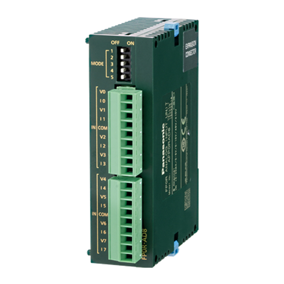
Analog i/o unit
Hide thumbs
Also See for FP0R Series:
- User manual (349 pages) ,
- Programming manual (1334 pages) ,
- User manual (281 pages)
Table of Contents
Advertisement
Advertisement
Table of Contents


Need help?
Do you have a question about the FP0R Series and is the answer not in the manual?
Questions and answers